2 layers43 × 43 mm
TurboCAN
henrikssn/TurboCAN
This is the official repository for the TurboCAN controller board, designed specifically for the Voron AfterBurner toolhead but can also be used on similar toolheads using NEMA17 steppers.
88 parts82
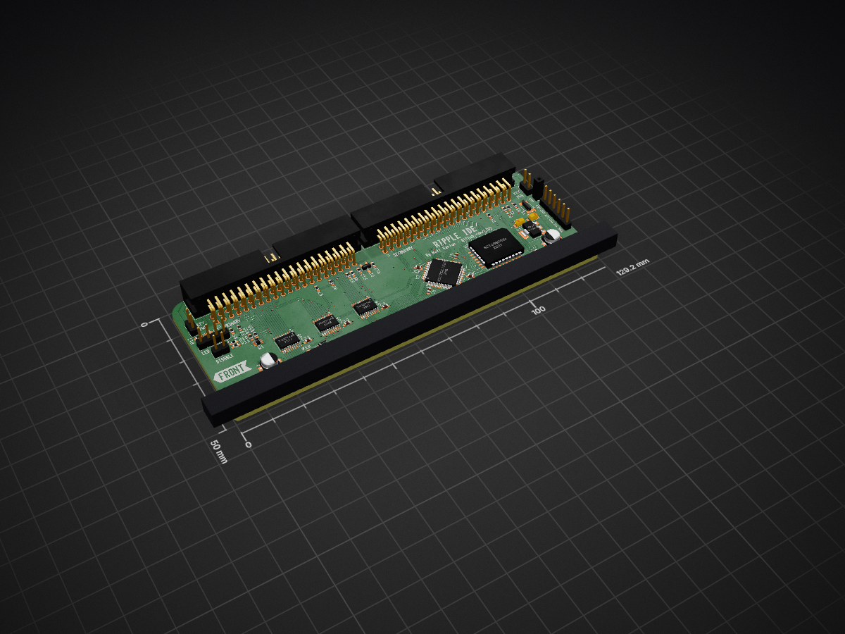
 LIV2/RIPPLE-IDE41
Zorro 2 IDE Interface for Amiga 2000/3000/4000
RIPPLE is an open-source printed circuit board by LIV2, from the LIV2/RIPPLE-IDE repository on GitHub, published under the GPL-2.0 licence. It is a 2-layer board of 129.2 × 50 mm with 61 parts on 151 nets, routed with 1,715 tracks and 301 vias.
It is built around the 74HCT245, LM1117-3.3 and BAT42W, with the BAT54A and BC857BS among its other parts. Its parts include 18 resistors, 12 capacitors, 9 connectors, 6 ICs and 3 diodes. It belongs with the FPGA and CPLD boards of this library.


Zorro 2 IDE Interface for Amiga 2000/3000/4000
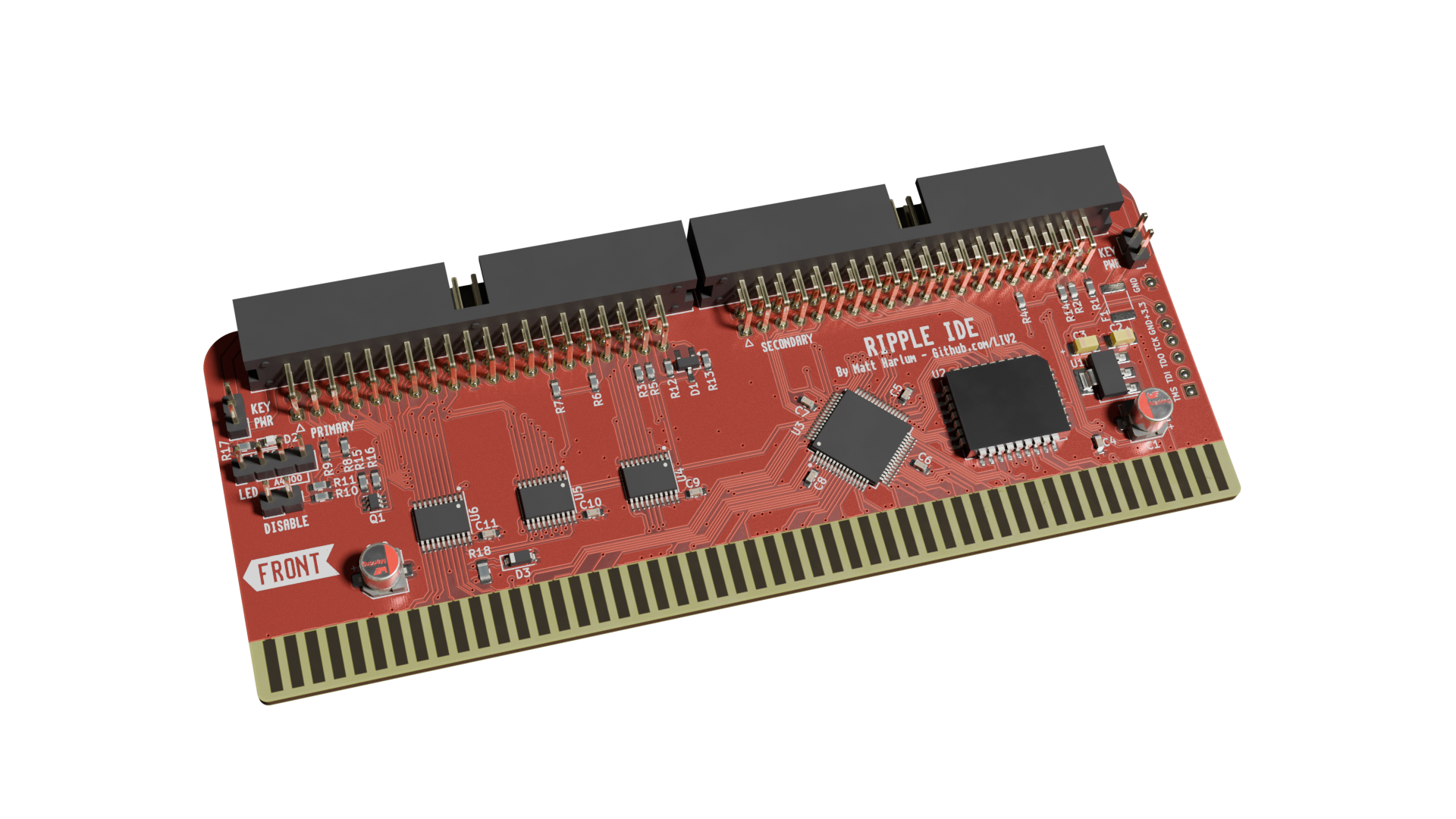
Tested and working.
For more information on these features please see the lide.device readme
| Jumper | Function |
|---|---|
| DISABLE | Disables the IDE interface |
| LED | The LED header has two positions: A2000 and A4000 Plug the HDD LED connector into the one relevant for your machine |
| KEY PWR | Closing this jumper enables 5V power on pin 20 for CompactFlash/IDE DOM modules |
You can find the latest Gerbers attached to the latest Release
I recommend ordering from JLCPCB as this board was designed within their 2-layer specifications
BOM and Placement files for JLCPCBs assembly service are provided and can be found inside the Gerbers folder and the Gerbers.zip file found under Releases
Recommended options when ordering:
To program the Flash, simply boot the latest lide-update.adf boot disk
The CPLD can be programmed using a Raspberry Pi as described by LinuxJedi
Revisions A3 and A4 had a silkscreen issue with R10/R11 labels swapped around - R10 (150 Ohm) should be above R11 (10K)
Thanks to:
RIPPLE IDE is covered by a GPL 2.0 Only license

| Qty | Value | Footprint | References |
|---|---|---|---|
| 9 | 10K | Resistor_SMD:R_0603_1608Metric_Pad0.98x0.95mm_HandSolder | R1, R4, R6, R7, R8, R9, R11, R12, R13 |
| 8 | 0.1u | Capacitor_SMD:C_0603_1608Metric_Pad1.08x0.95mm_HandSolder | C4, C5, C6, C7, C8, C9, C10, C11 |
| 4 | 68 | Resistor_SMD:R_0603_1608Metric_Pad0.98x0.95mm_HandSolder | R2, R3, R5, R14 |
| 3 | 74HCT245 | Package_SO:TSSOP-20_4.4x6.5mm_P0.65mm | U4, U5, U6 |
| 2 | 10u | Capacitor_SMD:C_1206_3216Metric_Pad1.33x1.80mm_HandSolder | C2, C3 |
| 2 | 150 | Resistor_SMD:R_0603_1608Metric_Pad0.98x0.95mm_HandSolder | R10, R17 |
| 2 | 1K | Resistor_SMD:R_0603_1608Metric_Pad0.98x0.95mm_HandSolder | R15, R16 |
| 2 | 47u | Capacitor_SMD:CP_Elec_5x5.3 | C1, C12 |
| 2 | Conn_01x02_Male | Connector_PinHeader_2.54mm:PinHeader_1x02_P2.54mm_Vertical | J2, J7 |
| 2 | Conn_02x20_Odd_Even | Connector_IDC:IDC-Header_2x20_P2.54mm_Horizontal | J3, J4 |
| 2 | G*** | kibuzzard-64A46D53 | kibuzzard-2, kibuzzard-8 |
| 1 | 68 | Resistor_SMD:R_0805_2012Metric_Pad1.20x1.40mm_HandSolder | R18 |
| 1 | ACT | LED_SMD:LED_0603_1608Metric_Pad1.05x0.95mm_HandSolder | D2 |
| 1 | BAT42W | Diode_SMD:D_SOD-123 | D3 |
| 1 | BAT54A | Package_TO_SOT_SMD:SOT-23_Handsoldering | D1 |
| 1 | BC857BS | Package_TO_SOT_SMD:SOT-363_SC-70-6 | Q1 |
| 1 | Disable | Connector_PinHeader_2.54mm:PinHeader_1x02_P2.54mm_Vertical | J5 |
| 1 | G*** | kibuzzard-64A40C97 | kibuzzard-3 |
| 1 | G*** | kibuzzard-64A44B62 | kibuzzard-10 |
| 1 | G*** | kibuzzard-64A40C7F | kibuzzard-6 |
| 1 | G*** | kibuzzard-64A3ECF2 | kibuzzard-7 |
| 1 | G*** | kibuzzard-64A46F4C | kibuzzard-5 |
| 1 | G*** | kibuzzard-6511D3C5 | kibuzzard-6511D3C5 |
| 1 | G*** | kibuzzard-64A46EB0 | kibuzzard-64A46EB0 |
| 1 | G*** | kibuzzard-64A44B19 | kibuzzard-9 |
| 1 | G*** | kibuzzard-64A46F3F | kibuzzard-4 |
| 1 | GND | Connector_PinHeader_2.54mm:PinHeader_1x01_P2.54mm_Vertical | J8 |
| 1 | JTAG | Connector_PinHeader_2.54mm:PinHeader_1x06_P2.54mm_Vertical | J1 |
| 1 | LED | Connector_PinHeader_2.54mm:PinHeader_1x04_P2.54mm_Vertical | J6 |
| 1 | LM1117-3.3 | Package_TO_SOT_SMD:SOT-223-3_TabPin2 | U1 |
| 1 | Polyfuse_Small | Fuse:Fuse_1812_4532Metric_Pad1.30x3.40mm_HandSolder | F1 |
| 1 | SST39SF010 | Package_LCC:PLCC-32_11.4x14.0mm_P1.27mm | U2 |
| 1 | XC9572XL-VQ64 | Package_QFP:TQFP-64_10x10mm_P0.5mm | U3 |
| 1 | Zorro2 | Zorro2:Zorro2-CardEdge | CN1 |
henrikssn/TurboCAN
This is the official repository for the TurboCAN controller board, designed specifically for the Voron AfterBurner toolhead but can also be used on similar toolheads using NEMA17 steppers.

AditeyaDC/BSPD
This is a repository containing files of a BSPD design used in FH+E 2026 and FB 2026.


twinoak/twinoak.meshcore.standard-repeater-design-v2
It was decided to go for a design which incorporated an LTE-M module for managinge the node. This gives almost 100% coverage(in Denmark at least!) and high bandwidth for firmware transfers.


lucedoriente/TI99-4A-internal-TIPI
This TIPI board is for use with danwerner21 (https://github.com/danwerner21/TI99_22.git) TI99-22 project

Kofen/PoE_Ethernet_GPIB_Adapter
This folder contains the necessary hardware files for the PoE Ethernet GPIB Adapter project.

It measures 129.2 × 50 mm and has 2 copper layers, 1.6 mm thick.
61 parts, built around the 74HCT245, LM1117-3.3, BAT42W and BAT54A. The full list of its parts is on this page, with links to each part's symbol and footprint where PCBKit's library has them.
From the LIV2/RIPPLE-IDE repository on GitHub, at the commit this page was made from: the board is Kicad/RIPPLE.kicad_pcb and its schematic Kicad/CPLD.kicad_sch. PCBKit opens the board in the browser, with nothing to install.
Its repository publishes it under the GPL-2.0 licence: you may reuse it on that licence's terms (keep the author's notice, and for a copyleft licence share your changes alike).