Skip to the content
2 layers43 × 43 mmTurboCAN, the printed circuit board in 3D

This is the official repository for the TurboCAN controller board, designed specifically for the Voron AfterBurner toolhead but can also be used on similar toolheads using NEMA17 steppers.

Size
43 × 43 mm
Copper layers
2
Thickness
1.6 mm
Parts
88
Nets
70
Pads
327
Tracks, vias
995, 144
Pours
3
Routed
Yes
KiCad
KiCad 5 (file 20171130)
Created
29 May 2021
Updated
9 Jul 2021

Overview

TurboCAN is an open-source printed circuit board by henrikssn, from the henrikssn/TurboCAN repository on GitHub. It is a 2-layer board of 43 × 43 mm with 88 parts on 70 nets, routed with 995 tracks and 144 vias.

It is built around the SN65HVD230D, TPS54331D and AO3400A, with the ADXL345BCCZ, AON7400A and SS54 among its other parts. Its parts include 31 resistors, 23 capacitors, 11 connectors, 9 ICs and 6 diodes. It belongs with the robots and motor control boards and the STM32 boards of this library.

Main components

7

README

README.md

TurboCAN

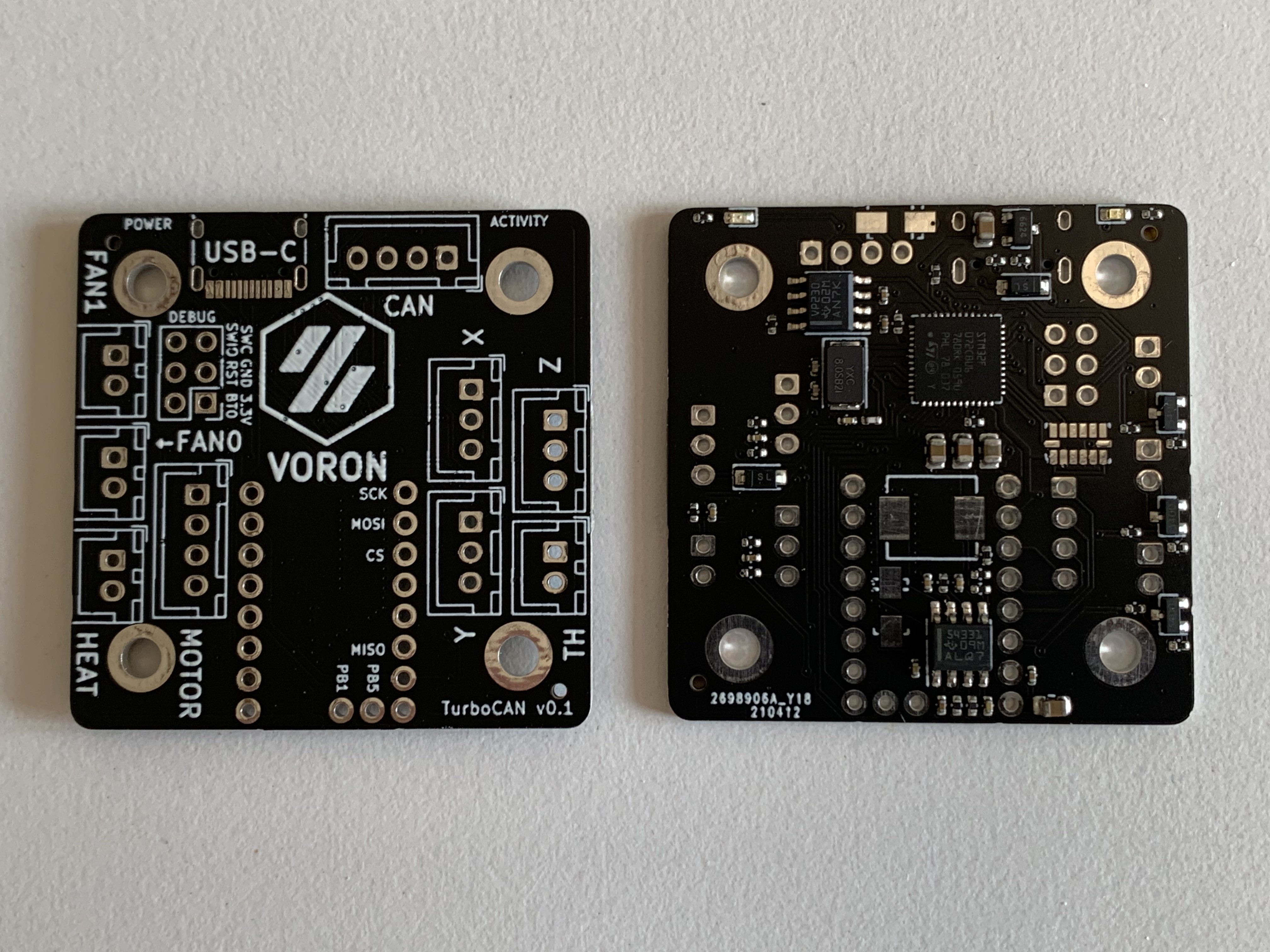
Image of TurboCAN board

This is the official repository for the TurboCAN controller board, designed specifically for the Voron AfterBurner toolhead but can also be used on similar toolheads using NEMA17 steppers. The main benefit of this board is the capability to run the toolhead over just 4 wires (CAN, +24V, Ground) which greatly simplifies the wiring in the Voron v1 and v2 models.

Features

  • 1x Combined CAN-bus and 24V power port with polarity protection
  • 1x ADXL345 accelerometer for use with Klipper's input shaper feature
  • 1x 24V stepper stick mount and motor output
  • 3x 24V MOSFET fan0/fan1/heater outputs (up to 3A)
  • 2x 5V powered endstop inputs (marked X/Y), could be used for toolhead mounted endstops (microswitch or hall effect), filament runout sensor or 5V Z probe.
  • 1x 24V powered endstop input (marked Z) with built-in BAT42 diode, used for inductive probe on the AfterBurner but also supports microswitch based probing (e.g. Magprobe).
  • 1x Thermistor input with 4.7k pullup resistor
  • 1x USB-C port
  • 1x SWD debug port with BOOT0/RESET broken out
  • 5V 3A buck converter (available externally on X/Y endstops) and 3.3V 200mA linear regulator (internal only)
  • Power LED & Activity (PA1) LED

The board supports interfacing with Klipper both over CAN and USB-C (selectable when building the Klipper firmware).

Use cases

The TurboCAN board is actually not only useful as a toolhead board, here are some reasons why you want more of them:

  • Want even less wiring? TurboCAN fits on the back of any NEMA17 stepper, so you can mount TurboCAN boards on e.g. the A/B (or X/Y) steppers and run them over a shared CAN bus.
  • Need a USB to CAN interface? TurboCAN can do USB and CAN at the same time, so you can flash CandleLight firmware and use it as a USB-CAN interface.
  • Want input shaper but annoyed by the complicated SPI wiring needed for the ADXL345 board? Just use a spare TurboCAN board over USB(/CAN) instead.

Current status

WARNING: While the author has a working printer running a TurboCAN v0.1 board, this project is in early development, and most likely still has undiscovered issues. Build one at your own risk!

  • v0.1 boards ordered
  • v0.1 boards testing
    • LEDs
    • 3.3v LDO
    • SWD debug port
    • USB interface
    • Buck converter
    • Stepper stick
    • MOSFET outputs
    • CAN-bus + Flashing Klipper (CAN)
    • Thermistor input
    • X/Y endstop inputs
    • Z endstop input

Getting started

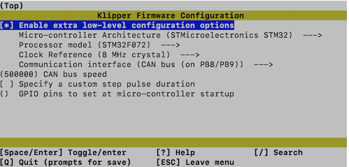
  1. Configure Klipper using make menuconfig:

Klipper menuconfig

  1. Put a jumper between BOOT0 and 3.3V and power cycle the board.

  2. Flash the TurboCAN board using make flash FLASH_DEVICE=1234:ABCD (replace USB vendor/product, you find them with lsusb).

  3. Connect the TurboCAN board using your favorite CAN bus interface (or use another TurboCAN board, see below).

  4. Run the klipper/scripts/canbus_query.py command to determine the CAN address. See Klipper docs for more info.

  5. Use the provided Klipper config as a starting point.

Changelog

v0.2

  • Errata fixes
    • LEDs are now mounted the right way.
    • R11 connected to R10/VSENSE.
    • SPI bus to the ADXL345 now have MISO/MOSI on the right pins.
    • Z probe input now has filtering and pullup resistor.
    • Reworked buck converter compensation circuitry.
    • Added CAN termination resistor.
  • Added 100uF bulk capacitor for 24V to mitigate voltage fluctuations due to long cables.
  • Thermistor resistor is now in 0805 package (was 0402) to simplify replacement to 1k (for PT1000 sensor).
  • Improved filtering of analog power domain to reduce ADC noise.
  • Replaced the heater mosfet with a more powerful AON7400A.
  • Replaced the +3.3V connection to MS1 with an unpopulated resistor to give the board UART address 0 by default.
  • Added optional pullup resistors to MS2/SPREAD to support standalone mode for the step stick.

Errata

v0.1

  • LEDs are mounted backwards.
    • Workaround: Reverse them (or simply skip, they aren't essential).
  • R11 not connected to R10/VSENSE.
    • Workaround: Simple to bodge as R10 is next to it.
  • MISO and MOSI are swapped on the SPI bus to the ADXL345.
    • Workaround: Use software SPI.
  • Z probe input lacks filtering and pullup resistor
    • Workaround: Use MCU internal pullup.
  • Higher than optimal noise from the buck converter leading to noisy accelerometer readings.
    • Workaround: Doesn't need one, performance is still good enough for input shaper.
  • No CAN termination resistors on-board
    • Workaround: Mount a 0603 120Ohm resistor between the H/L legs of the CAN JST-XH connector on each end of the bus.
  • Thermistor readings are noisy (fluctuating 2-3C) with a PT1000 sensor
    • Workaround: Use a B3950 or replace the pullup resistor with a 1k 0.5%

Developer Info

Generating fabrication outputs for JLCPCB

  1. Export Gerbers and drill file from pcbnew, make a zip file out of these.
  2. Generate a BOM csv using bom_csv_jlcpcb.py from kicad-jlcpcb-bom-plugin.
  3. Generate a CPL file from pcbnew.
  4. Convert the CPL file to JLCPCB format using using kicad_pos_to_cpl.py from kicad-jlcpcb-bom-plugin.

Attribution

Although this was designed from scratch, it was inspired by the Huvud board made by Pontus Borg.

License

For compability with other Voron projects, all included files are licensed under the GNU GPL-3 license.

Parts

88
QtyValueFootprintReferences
10100nFCapacitor_SMD:C_0402_1005MetricC2, C3, C4, C9, C10, C11, C12, C17, C20, C22
1010kResistor_SMD:R_0402_1005MetricR7, R8, R10, R14, R15, R16, R20, R21, R22, R27
61kResistor_SMD:R_0402_1005MetricR3, R12, R13, R23, R24, R28
4MountingHoleMountingHole:MountingHole_3.2mm_M3_DIN965_PadH1, H2, H3, H4
3100Resistor_SMD:R_0402_1005MetricR17, R18, R19
322uFCapacitor_SMD:C_0805_2012MetricC13, C14, C15
3DNPResistor_SMD:R_0402_1005MetricR29, R30, R31
210nFCapacitor_SMD:C_0402_1005MetricC6, C19
210uFCapacitor_SMD:C_0805_2012MetricC1, C5
212pFCapacitor_SMD:C_0402_1005MetricC16, C18
25.1kResistor_SMD:R_0402_1005MetricR1, R2
268kResistor_SMD:R_0402_1005MetricR5, R6
2AO3400APackage_TO_SOT_SMD:SOT-23U5, U6
2Ferrite beadInductor_SMD:L_0805_2012MetricL2, L3
2SS54digikey-footprints:DO-214ACD2, D3
11.2kResistor_SMD:R_0402_1005MetricR11
1100uFCapacitor_SMD:CP_Elec_8x10C21
1120OhmResistor_SMD:R_0805_2012MetricR26
11nFCapacitor_SMD:C_0402_1005MetricC7
11pFCapacitor_SMD:C_0402_1005MetricC8
11uFCapacitor_SMD:C_0402_1005MetricC23
1330kResistor_SMD:R_0402_1005MetricR4
14.7kResistor_SMD:R_0805_2012MetricR9
16.8uHKiCAD-Components:L_SMD_7.3x6.8L1
1680Resistor_SMD:R_0402_1005MetricR25
1ADXL345BCCZdigikey-footprints:LGA-14_3x5mm_RevAU9
1AON7400Aturbocan:DFN-8-1EP_3x3mm_P0.65mm_EP1.7x2.05mm_Thermal_PadU7
1AP2127N-3.3Package_TO_SOT_SMD:SOT-23U1
1BAT42WDiode_SMD:D_SOD-123D4
1BAT42W-VDiode_SMD:D_SOD-123D1
1CAN_PORTConnector_JST:JST_XH_B4B-XH-A_1x04_P2.50mm_VerticalJ10
1CrystalCrystal:Crystal_SMD_5032-2Pin_5.0x3.2mmY1
1DEBUGConnector_PinHeader_2.54mm:PinHeader_2x03_P2.54mm_VerticalJ5
1ENDSTOPXConnector_JST:JST_XH_B3B-XH-A_1x03_P2.50mm_VerticalJ7
1ENDSTOPYConnector_JST:JST_XH_B3B-XH-A_1x03_P2.50mm_VerticalJ8
1FAN0Connector_JST:JST_XH_B2B-XH-A_1x02_P2.50mm_VerticalJ11
1FAN1Connector_JST:JST_XH_B2B-XH-A_1x02_P2.50mm_VerticalJ12
1HEATConnector_JST:JST_XH_B2B-XH-A_1x02_P2.50mm_VerticalJ13
1LED_GreenLED_SMD:LED_0603_1608MetricD6
1LED_RedLED_SMD:LED_0603_1608MetricD5
1PROBEConnector_JST:JST_XH_B3B-XH-A_1x03_P2.50mm_VerticalJ14
1SN65HVD230Package_SO:SOIC-8_3.9x4.9mm_P1.27mmU3
1STEPPERConnector_JST:JST_XH_B4B-XH-A_1x04_P2.50mm_VerticalJ2
1STM32F072CBUxPackage_DFN_QFN:QFN-48-1EP_7x7mm_P0.5mm_EP5.6x5.6mmU8
1TH0Connector_JST:JST_XH_B2B-XH-A_1x02_P2.50mm_VerticalJ9
1TMC2209StepStickuser:TMC2209StepStickU2
1TPS54331Package_SO:SOIC-8_3.9x4.9mm_P1.27mmU4
1USB_C_Receptacle_USB2.0Connector_USB:USB_C_Receptacle_HRO_TYPE-C-31-M-12J1

Similar boards

  • 2 layers27.4 × 70.6 mmConnector board b, the printed circuit board in 3D

    Connector board b

    twinoak/twinoak.meshcore.standard-repeater-design-v2

    It was decided to go for a design which incorporated an LTE-M module for managinge the node. This gives almost 100% coverage(in Denmark at least!) and high bandwidth for firmware transfers.

    46 partsMIT
  • 2 layers129.2 × 50 mmRIPPLE, the printed circuit board in 3D

    RIPPLE

    LIV2/RIPPLE-IDE

    Zorro 2 IDE Interface for Amiga 2000/3000/4000

    61 parts41GPL-2.0
  • 2 layers63.3 × 63.3 mmBSPD, the printed circuit board in 3D

    BSPD

    AditeyaDC/BSPD

    This is a repository containing files of a BSPD design used in FH+E 2026 and FB 2026.

    130 partsMIT
  • 4 layers159.1 × 99.9 mmLoTI Board, the printed circuit board in 3D

    LoTI Board

    devtank-ltd/kicad_hiltop_loti_board

    KiCAD files for Loti card for HILTOP

    452 parts
  • 2 layers70 × 91 mmMerged lights, the printed circuit board in 3D

    Merged lights

    leogmendoza/skateboard-f25

    Building an electric skateboard!💨

    74 parts2
  • 4 layers85 × 54 mmManila ice, the printed circuit board in 3D

    Manila ice

    joshtyler/manila-ice

    Lattice iCE HX4K Development Board

    158 parts10
  • 2 layers100 × 100 mmFuentes, the printed circuit board in 3D

    Fuentes

    darioGg3/PowerSuppliesTester

    97 parts1GPL-3.0
  • 6 layers40.2 × 20 mmUSBHub, the printed circuit board in 3D

    USBHub

    jwpleow/USBHub

    253 parts1

Questions

How big is the TurboCAN PCB?

It measures 43 × 43 mm and has 2 copper layers, 1.6 mm thick.

What parts does the TurboCAN use?

88 parts, built around the SN65HVD230D, TPS54331D, AO3400A and ADXL345BCCZ. The full list of its parts is on this page, with links to each part's symbol and footprint where PCBKit's library has them.

Where can I download the TurboCAN KiCad files?

From the henrikssn/TurboCAN repository on GitHub, at the commit this page was made from: the board is hardware/turbocan.kicad_pcb. PCBKit opens the board in the browser, with nothing to install.

Can I use the TurboCAN design in my own project?

Its repository states no licence, so its author keeps all rights: ask henrikssn before reusing the design.