Skip to the content
2 layers99.1 × 99.1 mmConnector test stand, the printed circuit board in 3D

Connector test stand

L0czek/rakieta

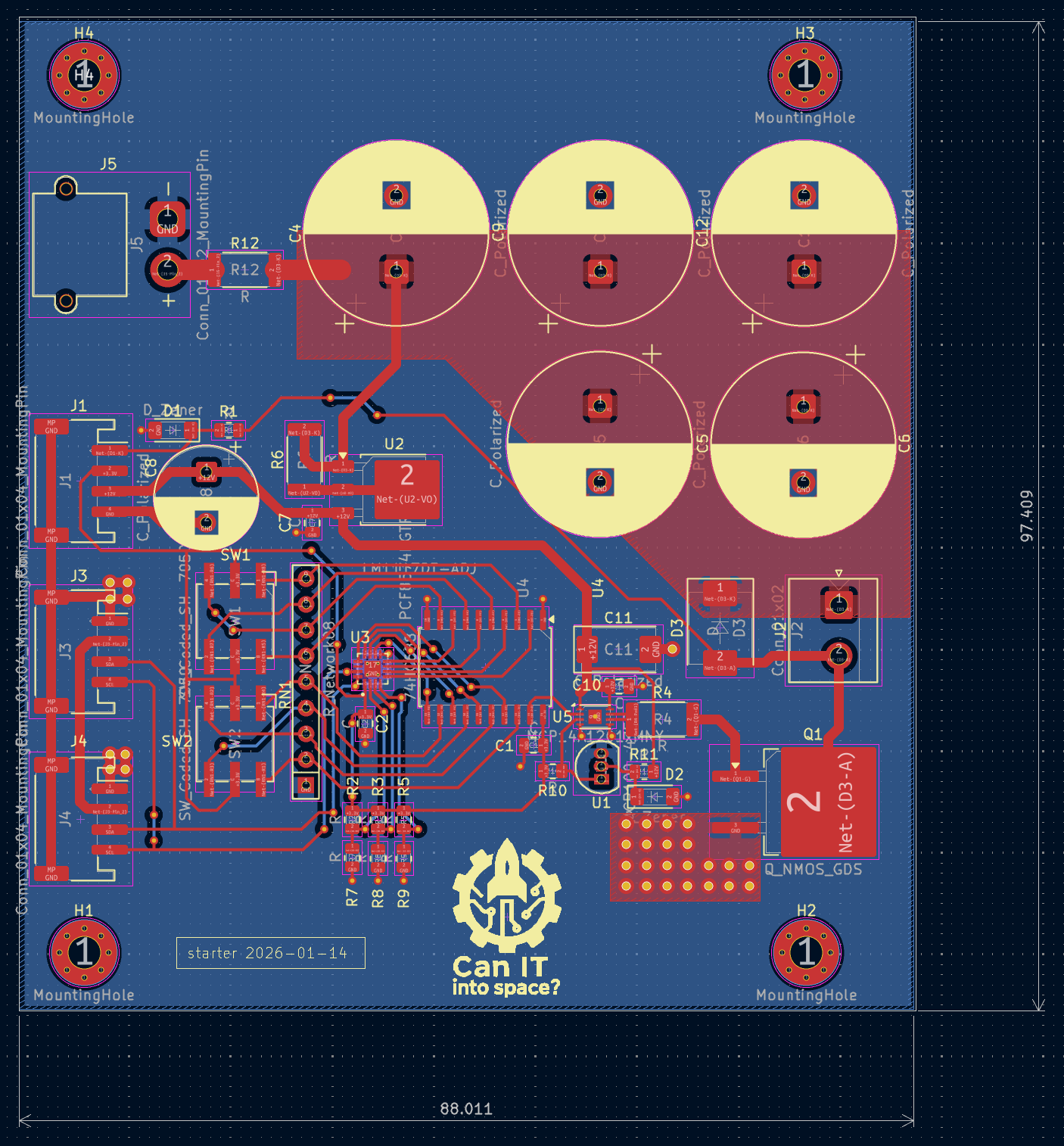
The starter board provides the ignition impulse to fire the engine. It includes an I2C IO expander and an 8-channel digital comparator to require a correct safety byte/address to be present before firing.

Size
99.1 × 99.1 mm
Copper layers
2
Thickness
1.6 mm
Parts
86
Nets
90
Pads
394
Tracks, vias
771, 99
Pours
1
Routed
Yes
KiCad
KiCad 9.0 (file 20241229)
Created
24 Jun 2025
Updated
8 Sep 2026

Overview

Connector test stand is an open-source printed circuit board by L0czek, from the L0czek/rakieta repository on GitHub. It is a 2-layer board of 99.1 × 99.1 mm with 86 parts on 90 nets, routed with 771 tracks and 99 vias.

It is built around the SN74LVC1G125DBV, 74LS540PC and SN65HVD11HD, with the 74AHCT1G04GV, CDSOT236-0504C and P82B96D among its other parts. Its parts include 19 resistors, 15 capacitors, 12 ICs, 12 connectors and 9 fuses.

Main components

10

README

starter/README.md

Starter board

Purpose

The starter board provides the ignition impulse to fire the engine. It includes an I2C IO expander and an 8-channel digital comparator to require a correct safety byte/address to be present before firing. The rocket engine is fired by discharging a large battery of capacitors via a high power mosfet.

Features

  • Safety: ignition only occurs when the correct I2C address/byte is presented to the IO expander. The sent byte is later compared with fixed value that can be set by encoders on PCB.
  • Igniter presence sensing (so an ignition attempt can be inhibited if no igniter detected)

PCB

Parts

86
QtyValueFootprintReferences
12100nFCapacitor_SMD:C_0805_2012MetricC1, C2, C3, C4, C5, C6, C8, C9, C12, C13, C14, C15
8FuseFuse:Fuseholder_Clip-5x20mm_Schurter_CQM_Inline_P20.60x5.00mm_D1.00mm_HorizontalF2, F3, F4, F5, F6, F7, F8, F9
7FerriteBeadInductor_SMD:L_0805_2012MetricFB1, FB2, FB3, FB4, FB5, FB6, FB7
7RResistor_SMD:R_0805_2012MetricR1, R2, R3, R4, R5, R6, R16
4MountingHole_PadMountingHole:MountingHole_3.2mm_M3_Pad_ViaH1, H2, H3, H4
310KResistor_SMD:R_0805_2012MetricR9, R14, R15
3Conn_01x04_MountingPinConnector_JST:JST_PH_S4B-PH-SM4-TB_1x04-1MP_P2.00mm_HorizontalJ5, J9, J10
21000uF 16VCapacitor_SMD:CP_Elec_10x10C7, C10
210K 1%Resistor_SMD:R_0805_2012MetricR10, R11
210R thick filmResistor_SMD:R_0805_2012MetricR20, R21
21KPotentiometer_THT:Potentiometer_Bourns_3266W_VerticalRV1, RV4
2330RResistor_SMD:R_0805_2012MetricR17, R18
2BAT54WPackage_TO_SOT_SMD:SOT-323_SC-70D2, D3
2Conn_01x02Connector_AMASS:AMASS_XT30PW-M_1x02_P2.50mm_HorizontalJ1, J6
2Conn_01x02TerminalBlock:TerminalBlock_Altech_AK300-2_P5.00mmJ2, J3
2SN74LVC1G125DBVPackage_TO_SOT_SMD:SOT-23-5U6, U8
1100RResistor_SMD:R_0805_2012MetricR12
110RResistor_SMD:R_0805_2012MetricR19
112KPotentiometer_THT:Potentiometer_Bourns_3266W_VerticalRV3
14K1Resistor_SMD:R_0805_2012MetricR13
174AHCT1G04Package_TO_SOT_SMD:SOT-23-5U11
174LS540Package_SO:SO-20_12.8x7.5mm_P1.27mmU4
1CCapacitor_SMD:C_0805_2012MetricC11
1CDSOT236-0504CPackage_TO_SOT_SMD:SOT-23-6U12
1Conn_01x03TerminalBlock:TerminalBlock_Altech_AK300-3_P5.00mmJ7
1Conn_01x05TerminalBlock_Altech:Altech_AK100_1x05_P5.00mmJ4
1Conn_01x10TerminalBlock_4Ucon:TerminalBlock_4Ucon_1x10_P3.50mm_HorizontalJ8
1DDiode_SMD:D_SMBD1
1DE9_Socket_MountingHolesConnector_Dsub:DSUB-9_Socket_Horizontal_P2.77x2.84mm_EdgePinOffset9.90mm_Housed_MountingHolesOffset11.32mmJ11
1DVI-I_Dual_LinkConnector_Video:DVI-I_Molex_74320-1004_HorizontalJ12
1FuseFuse:Fuseholder_Cylinder-5x20mm_Bulgin_FX0456_Vertical_ClosedF1
1G2RL-1-ERelay_THT:Relay_SPDT_Omron_G2RL-1-EK1
1INA333xxDGKPackage_SO:VSSOP-8_3x3mm_P0.65mmU2
1LOGOshared:logo20x20G***
1MCP1501-40xSNPackage_SO:SOIC-8_3.9x4.9mm_P1.27mmU13
1OPA333xxDPackage_SO:SOIC-8_3.9x4.9mm_P1.27mmU5
1P82B96Package_SO:SOIC-8_3.9x4.9mm_P1.27mmU9
1PCF8574RGTRth:QFN50P300X300X100-17NU1
1SN65HVD11HDPackage_SO:SOIC-8_3.9x4.9mm_P1.27mmU10
1TBD62783APackage_SO:SOP-18_7x12.5mm_P1.27mmU7

More from L0czek/rakieta

4
  • 4 layers55.7 × 46.4 mmBlackbox, the printed circuit board in 3D

    Blackbox

    L0czek/rakieta

    The starter board provides the ignition impulse to fire the engine. It includes an I2C IO expander and an 8-channel digital comparator to require a correct safety byte/address to be present before firing.

    64 parts
  • 2 layers97.3 × 100.3 mmConnector main computer, the printed circuit board in 3D

    Connector main computer

    L0czek/rakieta

    The starter board provides the ignition impulse to fire the engine. It includes an I2C IO expander and an 8-channel digital comparator to require a correct safety byte/address to be present before firing.

    62 parts
  • 2 layers88.3 × 97.8 mmStarter, the printed circuit board in 3D

    Starter

    L0czek/rakieta

    The starter board provides the ignition impulse to fire the engine. It includes an I2C IO expander and an 8-channel digital comparator to require a correct safety byte/address to be present before firing.

    45 parts
  • 2 layers71.7 × 65.2 mmSensor tmp107, the printed circuit board in 3D

    Sensor tmp107

    L0czek/rakieta

    The starter board provides the ignition impulse to fire the engine. It includes an I2C IO expander and an 8-channel digital comparator to require a correct safety byte/address to be present before firing.

    18 parts

Similar boards

  • 4 layers128 × 79 mmBMS, the printed circuit board in 3D

    BMS

    eChook/BMS-Comms-Board

    [PCB][KiCad] PCB Files for BMS Comms Master Board

    229 parts2
  • 4 layers100 × 100 mmDMX servo controller hardware, the printed circuit board in 3D

    DMX servo controller hardware

    flavioamieiro/dmx_servo_controller

    This source describes Open Hardware and is licensed under the CERN-OHL-S v2. You may redistribute and modify this source and make products using it under the terms of the CERN-OHL-S v2.

    63 parts1
  • 4 layers99.6 × 99.9 mmRailclock, the printed circuit board in 3D

    Railclock

    L0czek/railclock

    This PCB exposes 11 GPIOs via JST connectors for sensors and actuators. It can run without an external 5V supply by using an on-board battery charger and a boost converter to create a 12V rail for motors and…

    172 parts
  • 2 layers52 × 45 mmGeneralNode, the printed circuit board in 3D

    GeneralNode

    SanchakGarg/Hexagon-generator

    25 parts
  • 2 layers83.1 × 77.3 mmManhattanPanels SOT23-6, the printed circuit board in 3D

    ManhattanPanels SOT23-6

    pris-digital/ManhattanBreakoutBoards-Panelized

    A collection of breakout boards for manhattan style prototyping

    1,071 partsGPL-3.0
  • 4 layers65 × 30 mmElec gripette hub and dyn, the printed circuit board in 3D

    Elec gripette hub and dyn

    pollen-robotics/elec_grabette

    Set of electronic boards for Grabette/Gripette

    122 parts11Apache-2.0
  • 4 layers65 × 30.9 mmElec RPI Robot HAT, the printed circuit board in 3D

    Elec RPI Robot HAT

    armature-ai-labs/indieduck

    Open robot prototype: editable FreeCAD CAD, printable parts and fit-test documentation. Adapted from Open Duck Mini.

    132 partsApache-2.0

Questions

How big is the Connector test stand PCB?

It measures 99.1 × 99.1 mm and has 2 copper layers, 1.6 mm thick.

What parts does the Connector test stand use?

86 parts, built around the SN74LVC1G125DBV, 74LS540PC, SN65HVD11HD and 74AHCT1G04GV. The full list of its parts is on this page, with links to each part's symbol and footprint where PCBKit's library has them.

Where can I download the Connector test stand KiCad files?

From the L0czek/rakieta repository on GitHub, at the commit this page was made from: the board is connector-test-stand/connector-test-stand.kicad_pcb and its schematic blackbox/blackbox.kicad_sch. PCBKit opens the board in the browser, with nothing to install.

Can I use the Connector test stand design in my own project?

Its repository states no licence, so its author keeps all rights: ask L0czek before reusing the design.