2 layers48.2 × 24.9 mm
Temp sensor
juniper-garden/twig_temp_humidity_sensor
Hardware files for the temperature and humidity sensor
56 partsGPL-3.0

 Jan-IngenHousz-Institute/miniPar
Repository firmware for the ambit PAR meter version
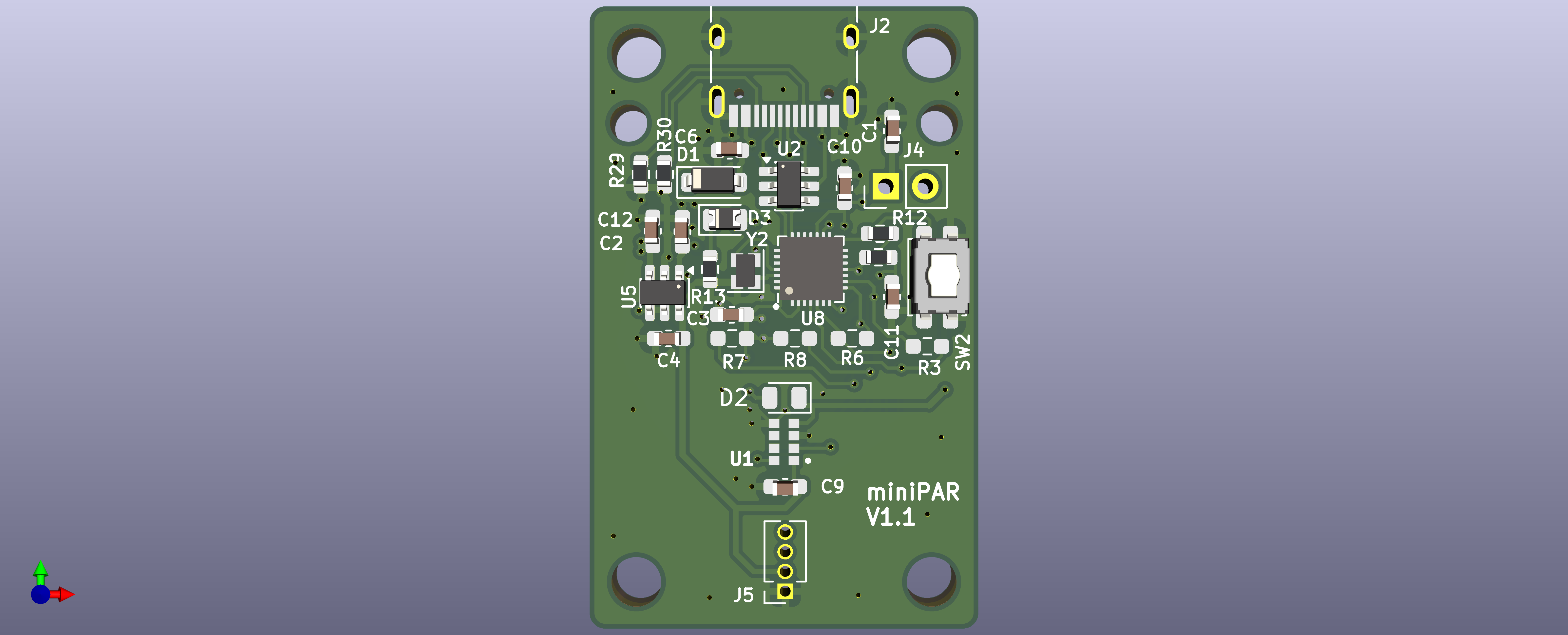
MiniParMain is an open-source printed circuit board by Jan-IngenHousz-Institute, from the Jan-IngenHousz-Institute/miniPar repository on GitHub, published under the MIT licence. It is a 4-layer board of 25 × 40 mm with 36 parts on 37 nets, routed with 372 tracks and 104 vias.
It is built around the ESP8685H4, AS7341-DLGT and BME280, with the IP4234CZ6, LIS2DE12 and 1N4148WT among its other parts. Its parts include 12 capacitors, 10 resistors, 6 ICs, 3 diodes and 3 connectors.


Commands are sent as plain text terminated with \n. JSON mode is also supported — send a valid JSON object and the device will respond in JSON.
hello
MiniPAR,1.1 (plain) / {"device":"MiniPAR","version":"1.1"} (JSON)reboot
Ready.delay_ms,<value>
delay_ms,500<value> milliseconds, then responds with the delay value: 500 (plain) / {"delay_ms":500} (JSON). Missing/negative value is treated as 0.battery
NaN (plain) / {"battery":"NaN"} (JSON)i2c_scan
0x39)spec[,<count>]
{"spectrometer":{"model":"AS7341","channels":{"f1_415":1.2345,"f2_445":6.7890,...},"par":123.45}} (JSON) / model,ch0,ch1,...,par (plain)raw_reading / gain / integration_time_ms (counts per millisecond per gain unit). Values are comparable across different gain and integration-time settings.hello's firmware version if you interpret them.par command), computed from this same reading.<count> repeats the measurement that many times (omit, or 1, for a single reading); each reading is printed as soon as it's taken. With <count> > 1: JSON response becomes an array of the single-reading objects ([{"spectrometer":{...}},{"spectrometer":{...}},...]); plain response is the single-reading lines joined with ; on one line.spec_raw
spec but raw unscaled integer counts (no normalization applied).spec_flash,<mA>
spec_flash,10dark:<values>;lit:<values>;diff:<values> (plain).spec_set_atime,<0-255>
spec_set_astep,<0-65534>
spec_set_gain,<0-10 (AS7341) | 0-12 (AS7343)>
spec_status or status
model=<name>,available=<0|1>,atime=<val>,astep=<val>,gain=<val> (plain)set_led,<mA>
set_led,20{"spectrometer":{"led_current_ma":20}} (JSON) / actual mA set (plain)par[,<count>]
123.45y = a·par_raw + b<count> repeats the measurement that many times (omit, or 1, for a single reading); each reading is printed as soon as it's taken. With <count> > 1: JSON response becomes an array ([{"par":1.2},{"par":3.4},...]); plain response is the values joined with ; on one line.par_raw
1.23cal_par_slope,<value>
cal_par_slope,10.0{"calibration":{"slope":10.0}}a coefficient for y = ax + b scaling. Persisted to NVS.cal_par_intercept,<value>
cal_par_intercept,2.3{"calibration":{"intercept":2.3}}b coefficient for y = ax + b scaling. Persisted to NVS.get_cal_par
{"calibration":{"slope":10.0,"intercept":2.3}} (JSON) / slope=10.0,intercept=2.3 (plain)a (slope) and b (intercept) coefficients for y = ax + b scaling.set_spec_coeff,<channel>,<value>
set_spec_coeff,0,0.614975{"spectrometer_coeff":{"channel":0,"value":0.614975}}basic_counts() in new_calibration_miniPAR/as7341_calibrate.py — upload host-fitted coefficients directly, with no factor of 1000. Coefficients written by an earlier firmware are rescaled once on the first 1.06 boot.get_spec_coeff
{"spectrometer_coeffs":{"channels":{"0":0.614975,"1":0.053037,...}}}get_spec_coeff,<channel>
get_spec_coeff,0{"spectrometer_coeff":{"channel":0,"value":0.614975}}set_name,<string>
{"device_name":"MyDevice"}get_name
{"device_name":"MyDevice"}Detected automatically at boot (I2C address 0x76 or 0x77); all commands below respond with error:not_available (plain) / {"bme280":{"error":"not_available"}} (JSON) if no BME280 is fitted. Temperature, pressure, and humidity are all enabled by default, at the highest oversampling (x16), IIR filter off, one-shot read mode.
bme_status
continuous=<0|1>,continuous_active=<0|1>,temp_comp=<value>,temp_en=<0|1>,temp_osrs=<0-5>,press_en=<0|1>,press_osrs=<0-5>,hum_en=<0|1>,hum_osrs=<0-5>,iir=<0-4>{"bme280_status":{"available":true,"continuous_mode":false,"continuous_active":false,"temperature_compensation_c":0.00,"temperature":{"enabled":true,"oversampling":5},"pressure":{"enabled":true,"oversampling":5},"humidity":{"enabled":true,"oversampling":5},"iir_filter":0}}bme_set_temp_enable,<0|1>
bme_get_tph output. Temperature is still sampled internally regardless (pressure/humidity compensation depend on it) — this only affects reporting.bme_set_press_enable,<0|1>
bme_get_tph output.bme_set_hum_enable,<0|1>
bme_get_tph output.bme_set_temp_oversample,<0-5>
0=off (clamped to 1, since temperature must always be sampled), 1=x1, 2=x2, 3=x4, 4=x8, 5=x16 (default).bme_set_press_oversample,<0-5>
0=channel skipped by the sensor.bme_set_hum_oversample,<0-5>
0=channel skipped by the sensor.bme_set_iir,<0-4>
0=off (default), 1=x2, 2=x4, 3=x8, 4=x16.bme_set_continuous,<0|1>
0 (default) = one-shot: every bme_get_tph call takes its own forced-mode measurement.1 = continuous: the chip free-runs in normal mode; bme_get_tph blocks only on the first call after enabling (waiting for that first conversion), then returns whatever the chip's background cycle last produced.bme_set_temp_comp,<value>
bme_get_temp_comp
bme_get_tph[,<count>] (alias: tph[,<count>])
<temperature_c>,<pressure_hpa>,<humidity_pct> — positional CSV, blank field for a disabled channel.{"bme280":{"temperature_c":23.45,"pressure_hpa":1013.25,"humidity_pct":45.20}} — null for a disabled channel.bme_set_continuous: one-shot mode (default) takes a fresh forced-mode reading every call; continuous mode waits for the first conversion only on the first call after being enabled, then returns the most recent free-running reading on every call after that.<count> repeats the measurement that many times (omit, or 1, for a single reading); each reading is printed as soon as it's taken. With <count> > 1: JSON response becomes an array of the single-reading objects; plain response is the single-reading CSV rows joined with ; on one line.The LED on GPIO 10 provides a visual indication of spectrometer state:
| LED state | Meaning |
|---|---|
| Off | No spectrometer detected at boot |
| Solid on | Spectrometer detected, all channels within range |
| Blinking 20 Hz | At least one spectrometer channel is saturated |
Saturation is checked automatically on every spectrometer read (spec, spec_raw, par, par_raw, etc.). The LED returns to solid-on as soon as the next read finds all channels within range. Reduce gain or integration time (spec_set_gain, spec_set_atime, spec_set_astep) to clear saturation.
\n (\r is ignored)raw_reading / gain / integration_time_ms, where integration_time_ms = (ATIME+1) × (ASTEP+1) × 2.78e-3 ms. Used by spec, par, and par_raw — values are gain/integration-time independent. This is the ams AN000633 §2.1 convention; firmware ≤ 1.05 used seconds instead, see CALIBRATION.md.FW Design (L. Grabowski, L. Caracciolo),
HW Design (L. Grabowski)
| Qty | Value | Footprint | References |
|---|---|---|---|
| 11 | 2.2u | Capacitor_SMD:C_0603_1608Metric_Pad1.08x0.95mm_HandSolder | C1, C2, C3, C4, C5, C7, C8, C9, C10, C11, C12 |
| 6 | 5.1K | Resistor_SMD:R_0603_1608Metric | R2, R12, R13, R14, R29, R30 |
| 2 | 0R | Resistor_SMD:R_0603_1608Metric_Pad0.98x0.95mm_HandSolder | R3, R6 |
| 2 | 10K | Resistor_SMD:R_0603_1608Metric_Pad0.98x0.95mm_HandSolder | R7, R8 |
| 2 | LED | Diode_SMD:D_0805_2012Metric | D2, D3 |
| 1 | 10u | Capacitor_SMD:C_0603_1608Metric | C6 |
| 1 | 1N4148WT | Diode_SMD:D_SOD-123 | D1 |
| 1 | 40MHz | Crystal:Crystal_SMD_2016-4Pin_2.0x1.6mm | Y2 |
| 1 | AP7312-1833W6-7 | Package_TO_SOT_SMD:TSOT-23-6 | U5 |
| 1 | AS7341-DLGT | ambit_library:PSON80P310X200X110-8N | U1 |
| 1 | BME280 | Package_LGA:Bosch_LGA-8_2.5x2.5mm_P0.65mm_ClockwisePinNumbering | U3 |
| 1 | Conn_01x02_Pin | Connector_PinHeader_2.54mm:PinHeader_1x02_P2.54mm_Vertical | J4 |
| 1 | ESP8685 | Package_DFN_QFN:QFN-28-1EP_4x4mm_P0.4mm_EP2.6x2.6mm | U8 |
| 1 | IP4234CZ6 | Package_TO_SOT_SMD:SC-74-6_1.55x2.9mm_P0.95mm | U2 |
| 1 | LIS2DE12 | Package_LGA:LGA-12_2x2mm_P0.5mm | U9 |
| 1 | SW_Push | Button_Switch_SMD:SW_SPST_EVQP2_ShortPushTravel_H2.1mm | SW2 |
| 1 | USB_C_Receptacle | Connector_USB:USB_C_Receptacle_HRO_TYPE-C-31-M-12 | J2 |
| 1 | secondBoard | Connector_PinSocket_1.27mm:PinSocket_1x04_P1.27mm_Vertical | J5 |
juniper-garden/twig_temp_humidity_sensor
Hardware files for the temperature and humidity sensor


Global-Health-Engineering/plastic-scanner
Especially for small-scale recycling facilities and projects with limited financial resources, commercial plastic scanners are extremly expensive.

wandering-nora/SnowBackpack
A little driver for SnowPixel displays


PTR-projects/PTR_nano_hardware
Welcome to the KPPTR-hardware repository! This repository contains the design files for the hardware components used in the KPPTR project.

Scrarf/Neopixel-project-v3.0
PCB for ESP8685H4 WIFI based RGBW led driver.

zeankundev/boards
A collection and an archive of KiCad projects I made. Contains projects from 2023 - 2024.
It measures 25 × 40 mm and has 4 copper layers, 1.58 mm thick.
36 parts, built around the ESP8685H4, AS7341-DLGT, BME280 and IP4234CZ6. The full list of its parts is on this page, with links to each part's symbol and footprint where PCBKit's library has them.
From the Jan-IngenHousz-Institute/miniPar repository on GitHub, at the commit this page was made from: the board is KiCad/miniParMain.kicad_pcb and its schematic KiCad/miniParMain.kicad_sch. PCBKit opens the board in the browser, with nothing to install.
Its repository publishes it under the MIT licence: you may reuse it on that licence's terms (keep the author's notice, and for a copyleft licence share your changes alike).