Skip to the content
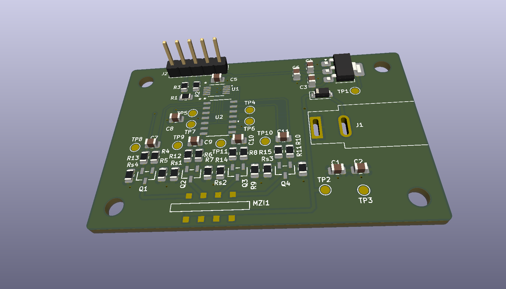
2 layers57.9 × 37.3 mmHeater driver, the printed circuit board in 3D

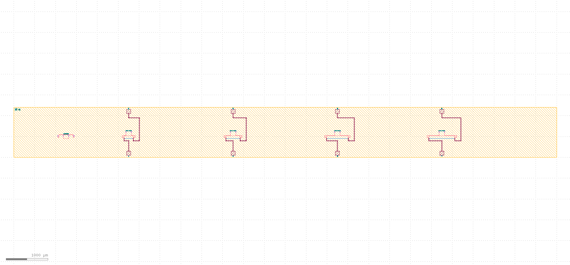
A Photonic Integrated Circuit (PIC) with four Mach Zender Interferometers (MZI) and associated operation/testing electronics combined into a small PCB.

Size
57.9 × 37.3 mm
Copper layers
2
Thickness
1.6 mm
Parts
56
Nets
32
Pads
132
Tracks, vias
173, 22
Pours
2
Routed
Yes
KiCad
KiCad 10.0 (file 20260206)
Created
1 Oct 2026
Updated
1 Oct 2026

Overview

Heater driver is an open-source printed circuit board by IanK02, from the IanK02/Mach-Zender-Interferometer-PIC repository on GitHub, published under the MIT licence. It is a 2-layer board of 57.9 × 37.3 mm with 56 parts on 32 nets, routed with 173 tracks and 22 vias.

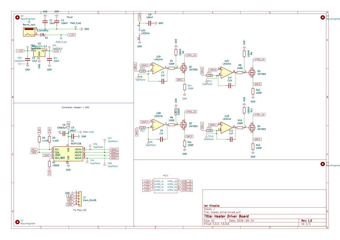
It is built around the LM324AD, MCP4728-E/UN and AMS1117-3.3. Its parts include 19 resistors, 11 capacitors, 4 transistors, 3 ICs and 2 connectors.

Main components

3

README

README.md

Mach-Zender Interferometer Photonic Integrated Circuit

A photonic integrated circuit designed in Python with gdsfactory, laid out in KLayout, with a companion PCB designed in KiCad.

Chip implements four Mach-Zender-Interferometers of varying lengths, with accompanying chip providing all required electrical usage and testing hardware.

Gallery

Die LayoutPCB 3D View
Full die layoutPCB 3D View
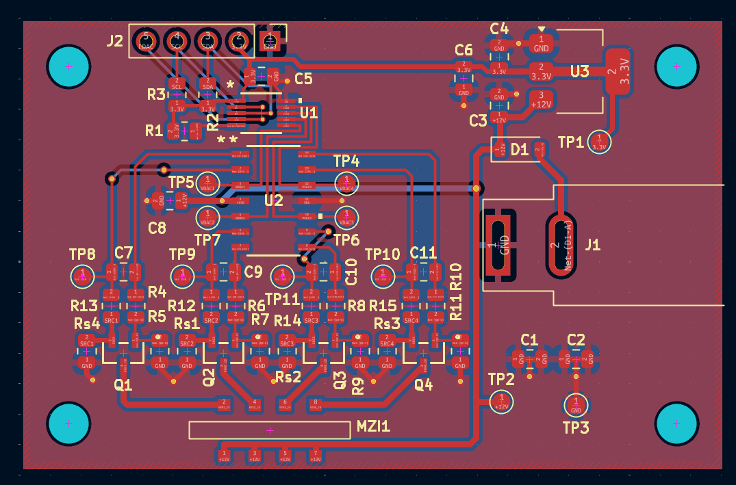
PCB 2D ViewCircuit Schematic
PCB 2D RenderCircuit Schematic

Features

  • Four MZIs with thermal phase shifters
  • 12V barrel jack connector for power
  • Glue-in spot on PCB for inserting MZI chip

PDK

This design uses gdsfactory's open-source generic PDK, so the whole layout can be regenerated and freely shared. Layer numbers and components are generic and not tied to any commercial foundry process.

Tools

  • gdsfactory: parametric layout in Python
  • KLayout: layout viewing and rendering
  • KiCad: schematic and PCB design

Parts

56
QtyValueFootprintReferences
11TestPointTestPoint:TestPoint_Pad_D1.5mmTP1, TP2, TP3, TP4, TP5, TP6, TP7, TP8, TP9, TP10, TP11
8100RResistor_SMD:R_0805_2012MetricR4, R6, R8, R10, Rs1, Rs2, Rs3, Rs4
5100kRResistor_SMD:R_0805_2012MetricR1, R5, R7, R9, R11
41kRResistor_SMD:R_0805_2012MetricR12, R13, R14, R15
41nFCapacitor_SMD:C_0805_2012MetricC7, C9, C10, C11
42N70022N7002:SOT-23TO-236_318-08_ONSQ1, Q2, Q3, Q4
4MountingHoleMountingHole:MountingHole_3.2mm_M3H1, H2, H3, H4
3100nFCapacitor_SMD:C_0805_2012MetricC2, C5, C8
310uFCapacitor_SMD:C_0805_2012MetricC1, C3, C6
24.4kRResistor_SMD:R_0805_2012MetricR2, R3
122uFCapacitor_SMD:C_0805_2012MetricC4
1AMS1117-3.3Package_TO_SOT_SMD:SOT-223-3_TabPin2U3
1Barrel_JackConnector_BarrelJack:BarrelJack_SwitchcraftConxall_RAPC10U_HorizontalJ1
1Conn_01x05Connector_PinHeader_2.54mm:PinHeader_1x05_P2.54mm_VerticalJ2
1D_SchottkyDiode_SMD:D_SOD-123D1
1LM324ALMX24:M14AU2
1MCP4728MCP4278:MSOP10_MC_MCHU1
1~PIC:PIC_MZI_DIEMZI1

Similar boards

  • 4 layers100 × 100 mmAFE, the printed circuit board in 3D

    AFE

    Blaze-Pascal/Masters-Multi-Channel_DAQ

    Custom 2-channel digital oscilloscope DAQ with 20MHz bandwidth. Built with a custom KiCad analog front-end (AFE) PCB, Gowin FPGA (Tang Nano 9K) for high-speed signal buffering (VHDL), and an RPi Pico MCU for SCPI-like…

    216 parts2GPL-3.0
  • 4 layers100 × 100 mmPower Supply, the printed circuit board in 3D

    Power Supply

    bernau01/zh_power_supply

    Power management for mobile robotic

    318 parts
  • 2 layersOmniStimDriverBoard PCB, the printed circuit board in 3D

    OmniStimDriverBoard PCB

    Hamza-Anver/OmniStimDriverBoard-PCB

    This is an evaluation board to test operating principles of the OptiStim head unit.

    99 parts
  • 2 layers113 × 65 mmOmniStimEvalBoard, the printed circuit board in 3D

    OmniStimEvalBoard

    Hamza-Anver/OmniStimEvalBoard-Hardware

    This is an evaluation board to test operating principles of the OptiStim head unit.

    102 parts
  • 4 layers54 × 102 mmSWC, the printed circuit board in 3D

    SWC

    OETSolutions/swc-module

    Steering-wheel-controls adapter module — ESP32-S3, KiCad schematic/PCB, JLCPCB assembly

    110 parts
  • 4 layers62.8 × 97.5 mmOceanAI, the printed circuit board in 3D

    OceanAI

    daniel360kim/OceanAI

    A robotic and software orientated ocean development.

    124 parts14MIT
  • 2 layers127 × 80 mmCassetteSDK-85, the printed circuit board in 3D

    CassetteSDK-85

    ForNextSoftwareDevelopment/8085

    Intel 8085 Assembler / Disassembler / SDK-85 Simulator

    33 parts8
  • 4 layers160 × 105.4 mmSolarCarECU, the printed circuit board in 3D

    SolarCarECU

    solarcaratuva/EmbeddedSystem

    UVA Solar Car Embedded Systems PCB design and ECU code

    231 parts7

Questions

How big is the Heater driver PCB?

It measures 57.9 × 37.3 mm and has 2 copper layers, 1.6 mm thick.

What parts does the Heater driver use?

56 parts, built around the LM324AD, MCP4728-E/UN and AMS1117-3.3. The full list of its parts is on this page, with links to each part's symbol and footprint where PCBKit's library has them.

Where can I download the Heater driver KiCad files?

From the IanK02/Mach-Zender-Interferometer-PIC repository on GitHub, at the commit this page was made from: the board is pcb/heater_driver.kicad_pcb and its schematic pcb/heater_driver.kicad_sch. PCBKit opens the board in the browser, with nothing to install.

Can I use the Heater driver design in my own project?

Its repository publishes it under the MIT licence: you may reuse it on that licence's terms (keep the author's notice, and for a copyleft licence share your changes alike).