
4 layers82.8 × 88.9 mm
Metal detector test
bobasaurus/lumber-plunder-metal-detector
A VLF induction balance metal detector with a wooden body
111 parts11GPL-3.0

 HearnChristian/polarimeter
4-layer KiCad photodiode polarimeter: low-noise transimpedance front-end (OPA381/OPA320), precision REF3425 reference, LT8609/LP5912 power. Schematic, PCB, gerbers + BOM.
Polarimeter is an open-source printed circuit board by HearnChristian, from the HearnChristian/polarimeter repository on GitHub. It is a 4-layer board of 99.7 × 74.5 mm with 66 parts on 88 nets, routed with 224 tracks and 64 vias.
It is built around the OPA2320AID, ADR130AUJZ-REEL7 and LP5912-3.3DRVR, with the PJ-037AH and TS01CQE among its other parts. Its parts include 34 capacitors, 16 resistors, 10 ICs, 2 diodes and 2 connectors.


A 4-layer mixed-signal PCB that reads optical polarization by measuring the photocurrent from a pair of photodiodes through a low-noise transimpedance signal chain. Designed in KiCad; this repository contains the full schematic, layout, fabrication outputs, and bill of materials.
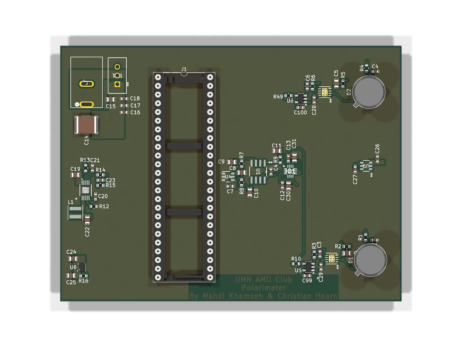
📄 Full schematic (PDF) · 🖼️ board bottom
Light passing through a polarizing optical stage lands on two photodiodes
(D1, D2). Each diode's photocurrent is converted to a voltage by a
transimpedance amplifier (TIA), filtered, and buffered for acquisition. By
comparing the two channels, the relative polarization / intensity of the
incident beam can be recovered. The board carries its own low-noise power
regulation and a precision voltage reference so the analog measurement is clean
and ratiometric.
| Stage | Part | Role |
|---|---|---|
| Photodiodes | D1, D2 (TO-5) | Convert incident light to photocurrent |
| Transimpedance amps | OPA381 (precision, low-bias TIA) | I→V conversion of diode current |
| Gain / buffer | OPA320 / OPA2320 (low-noise, R-R CMOS) | Second-stage gain and buffering |
| Precision reference | REF3425 (2.5 V) | Stable ratiometric reference for the ADC path |
| Connector | 2×24 header (J1) + barrel jack (J2) | Signal breakout and DC input |
F.Cu, In1.Cu, In2.Cu, B.CuPolarimeter.kicad_pro KiCad project
Polarimeter.kicad_sch Root schematic
Power.kicad_sch Power-supply sub-sheet (hierarchical)
Polarimeter.kicad_pcb PCB layout (4-layer)
Polarimeter.csv Bill of materials
Gerbers for AMO/ Fabrication outputs (Gerber + Excellon drill)
docs/ Rendered schematic PDF + 3D board imagesThe full BOM lives in Polarimeter.csv (designator,
footprint, quantity, value). Key actives: OPA381, OPA320/OPA2320, REF3425,
LT8609, LP5912-3.3.
Designed in KiCad. Open Polarimeter.kicad_pro to
view or edit the schematic and layout.
Designed by Christian Hearn, with Malik Shaaban.
| Qty | Value | Footprint | References |
|---|---|---|---|
| 6 | 0.1uF | Capacitor_SMD:C_0603_1608Metric | C4, C4, C28, C29, C99, C100 |
| 5 | 0.1u | Capacitor_SMD:C_0603_1608Metric | C1, C16, C17, C26, C27 |
| 4 | 1 uF | Capacitor_SMD:C_0805_2012Metric | C9, C10, C30, C31 |
| 4 | 1k | Resistor_SMD:R_0603_1608Metric | R1, R4, R7, R8 |
| 3 | 100k | Resistor_SMD:R_0603_1608Metric | R2, R5, R13 |
| 2 | 0.1uF | Capacitor_SMD:C_0805_2012Metric | C2, C5 |
| 2 | 10n | Capacitor_SMD:C_0603_1608Metric | C18, C21 |
| 2 | 24.7pF | Capacitor_SMD:C_0603_1608Metric | C3, C6 |
| 2 | 3.3nF | Capacitor_SMD:C_0603_1608Metric | C12, C13 |
| 2 | 49 | Resistor_SMD:R_0603_1608Metric | R10, R49 |
| 2 | 787 | Resistor_SMD:R_0603_1608Metric | R3, R6 |
| 2 | D_Photo | Package_TO_SOT_THT:TO-5-3 | D1, D2 |
| 2 | OPA320AIDBVR | Package_TO_SOT_SMD:SOT-23-5 | U5, U6 |
| 2 | OPA381AIDRBT | OPA381AIDRBT:DRB8_2P4X1P65 | U2, U3 |
| 1 | 0.1 | Resistor_SMD:R_0603_1608Metric | R9 |
| 1 | 0.1 uF | Capacitor_SMD:C_0603_1608Metric | C7 |
| 1 | 10 uF | Capacitor_SMD:C_0805_2012Metric | C11 |
| 1 | 10k | Resistor_SMD:R_0603_1608Metric | R16 |
| 1 | 10p | Capacitor_SMD:C_0603_1608Metric | C23 |
| 1 | 10u | Capacitor_SMD:C_0805_2012Metric | C15 |
| 1 | 10uF | Capacitor_SMD:C_0805_2012Metric | C8 |
| 1 | 18.2 kOhms | Resistor_SMD:R_0603_1608Metric | R12 |
| 1 | 187k | Resistor_SMD:R_0603_1608Metric | R15 |
| 1 | 1M | Resistor_SMD:R_0603_1608Metric | R14 |
| 1 | 1u | Capacitor_SMD:C_0603_1608Metric | C20 |
| 1 | 1u | Capacitor_SMD:C_0805_2012Metric | C24 |
| 1 | 2.2u | Inductor_SMD:L_Coilcraft_XxL4020 | L1 |
| 1 | 22u | Capacitor_SMD:C_0805_2012Metric | C22 |
| 1 | 4.7u | Capacitor_SMD:C_0805_2012Metric | C19 |
| 1 | 47u | Capacitor_SMD:C_2220_5750Metric | C14 |
| 1 | ADR130AUJZ-REEL7 | ADR130AUJZ-REEL7:UJ_6_ADI | U9 |
| 1 | ADS8355IRTET | ADS8355:QFN50P300X300X80-17N-D | IC1 |
| 1 | Conn_02x24_Counter_Clockwise | Package_DIP:DIP-48_W15.24mm_Socket_LongPads | J1 |
| 1 | LP5912-3.3DRV | Package_SON:WSON-6-1EP_2x2mm_P0.65mm_EP1x1.6mm_ThermalVias | U8 |
| 1 | LT8609EMSE-TRPBF | LT8609EMSE-TRPBF:05-08-1664_ADI | U7 |
| 1 | OPA2320AID | OPA2320AID:D8 | U1 |
| 1 | PJ-037AH | PJ-037AH:CONN_37AH | J2 |
| 1 | REF3425IDBVR | REF3425IDBVR:DBV0006A_N | U4 |
| 1 | TS01CQE | TS01CQE:TS01CQE_CNK | SW1 |
| 1 | v | Capacitor_SMD:C_0805_2012Metric | C25 |
bobasaurus/lumber-plunder-metal-detector
A VLF induction balance metal detector with a wooden body


RobertPHeller/RPi-RRCircuits
A collection of circuit designs for various MCUs, not just Raspberry Pis relating to Model Railroading

OpenDrone-hw/OpenFC-Lite-Mini
Open-source Betaflight flight controller. RP2354A, 20x20 mm, 6-layer, 3-6S, CERN-OHL-S-2.0.

OpenDrone-hw/OpenFC-Lite
Open-source Betaflight flight controller. RP2354B, 30.5x30.5 mm, 6-layer, 3-8S, CERN-OHL-S-2.0.

It measures 99.7 × 74.5 mm and has 4 copper layers, 1.6 mm thick.
66 parts, built around the OPA2320AID, ADR130AUJZ-REEL7, LP5912-3.3DRVR and PJ-037AH. The full list of its parts is on this page, with links to each part's symbol and footprint where PCBKit's library has them.
From the HearnChristian/polarimeter repository on GitHub, at the commit this page was made from: the board is Polarimeter.kicad_pcb and its schematic Polarimeter.kicad_sch. PCBKit opens the board in the browser, with nothing to install.
Its repository states no licence, so its author keeps all rights: ask HearnChristian before reusing the design.