2 layers147 × 105.9 mm
WirelessControllerESP32
EmmetGameDev/NevoltaNexusConsole
Repository for design files and code for the Nexus console.
66 parts4GPL-3.0

 Emrecanbl/ESP32_Power_Meter
ESP32-S3 based three-channel power meter with INA3221, 2.8" ILI9341 + XPT2046 LVGL UI, USB-C pass-through (power-only), TP4056 charging. FreeRTOS.
Esp32 F103 PowerMeter V1.0 is an open-source printed circuit board by Emrecanbl, from the Emrecanbl/ESP32_Power_Meter repository on GitHub. It is a 4-layer board of 41 × 77.8 mm with 47 parts on 70 nets, routed with 471 tracks and 61 vias.
It is built around the ESP32-S3-WROOM-1-N8, AMS1117-3.3 and TP4056-42-ESOP8. Its parts include 22 resistors, 8 connectors, 7 capacitors, 4 ICs and 3 diodes. It belongs with the sensors and measurement boards and the ESP32 boards of this library.


An ESP32-S3–based three-channel power meter built around INA3221. One channel supports USB-C pass-through so you can measure power flowing from USB-C IN → USB-C OUT; CC pins are tied for basic PD trigger behavior (power-only path).
Firmware stack: FreeRTOS. REST/WebSocket API is optional (may be added later). Live data can be streamed over USB-CDC; an optional ST7735 (160×128) SPI TFT can show basic status (no touch).
A custom 3D-printed enclosure is planned.
3 measurement channels via INA3221
ESP32-S3 (Wi‑Fi + native USB/CDC)
USB‑C pass‑through (1 channel): measure power across IN → OUT
Optional TFT: ST7735 (160×128) SPI for basic on-device status (no touch)
Battery: TP4056 Li‑ion charger + AMS1117‑3.3 LDO
Enclosure: custom 3D‑printed case (to be published)
Qt UI with Python and SQLite database integration
Added boot-time Check screen: verifies Wi‑Fi link and sensor health before entering the UI.
Check screen now shows connection status and the assigned IP address.
Main screen updated to display the device IP for quick access to the Web UI.
ST7735 (160×128) screen added (no touch).
Energy counter buttons are active (Start/Stop/Reset)
Sensor → UART JSON and Web UI hooked up
4-task FreeRTOS skeleton: sensor, screen, web, uart
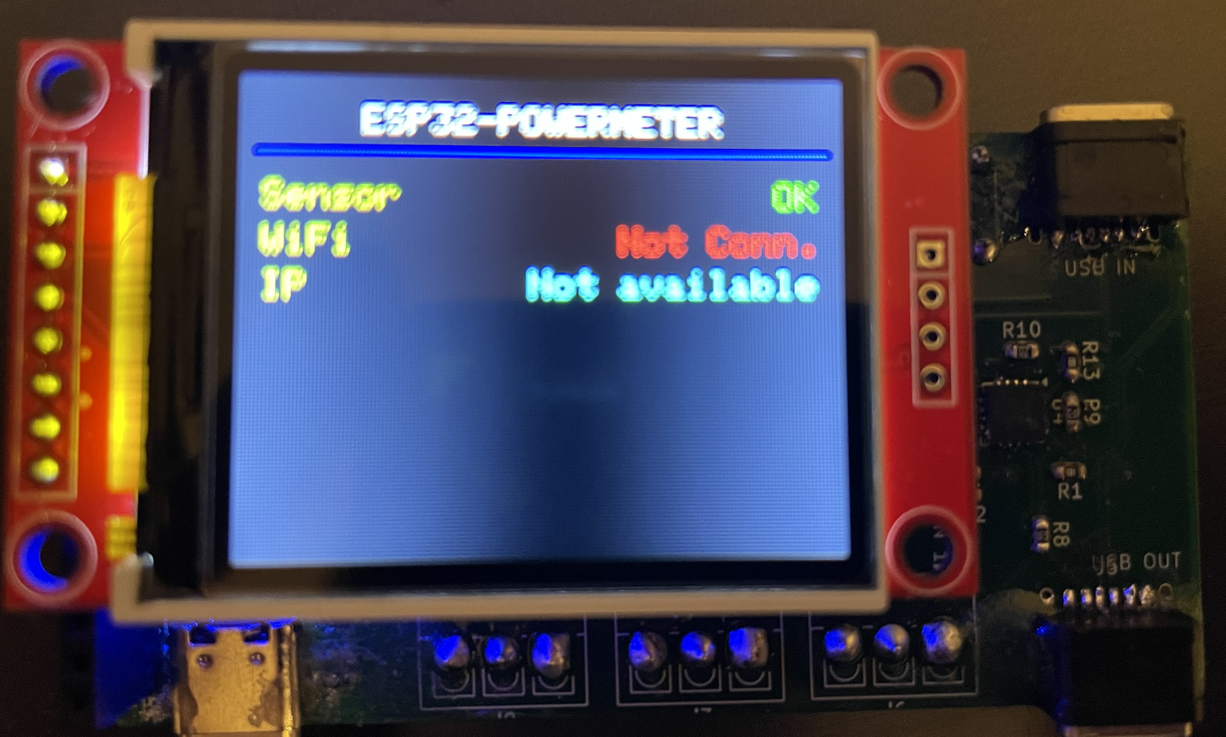
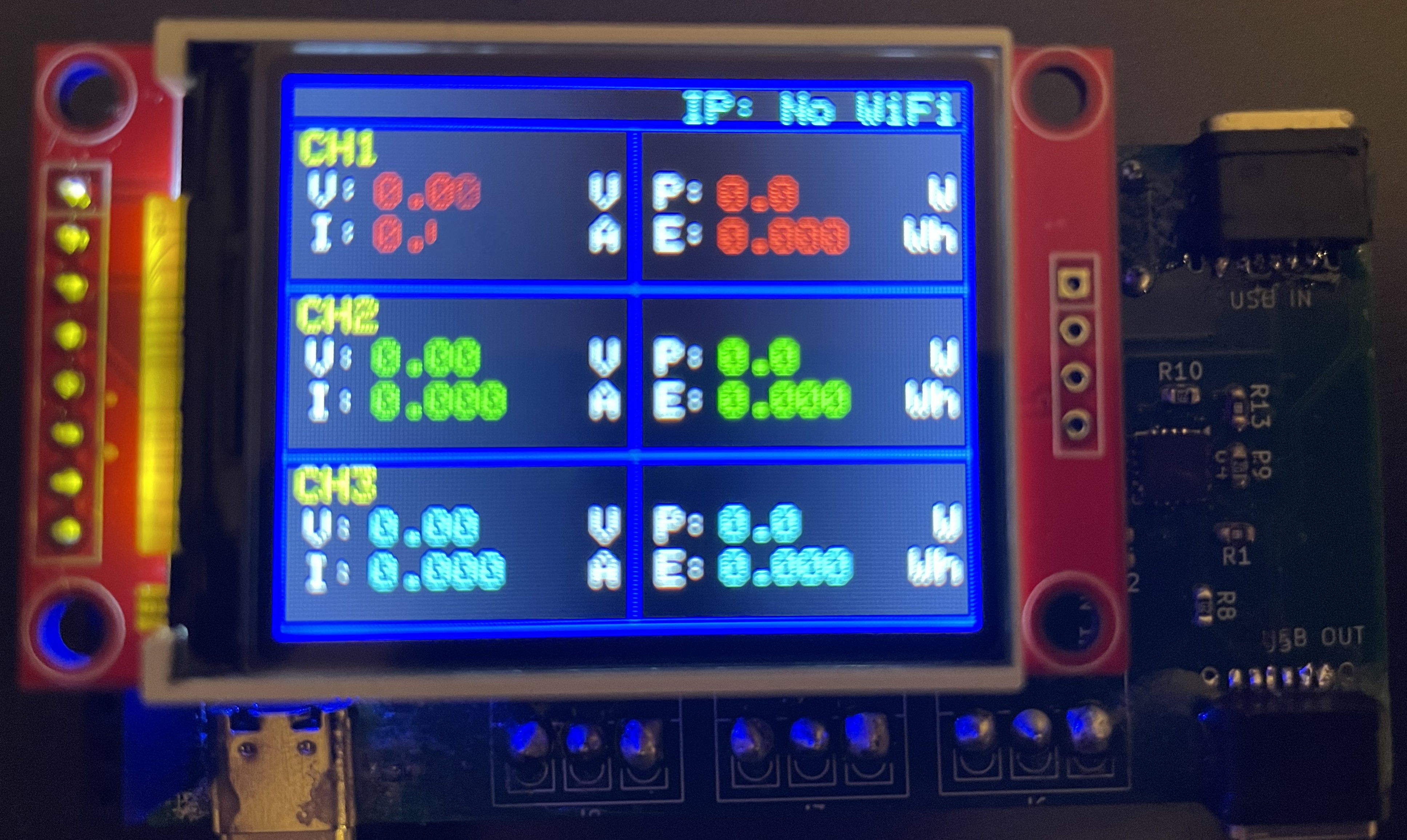
First Check Screen | Main Screen
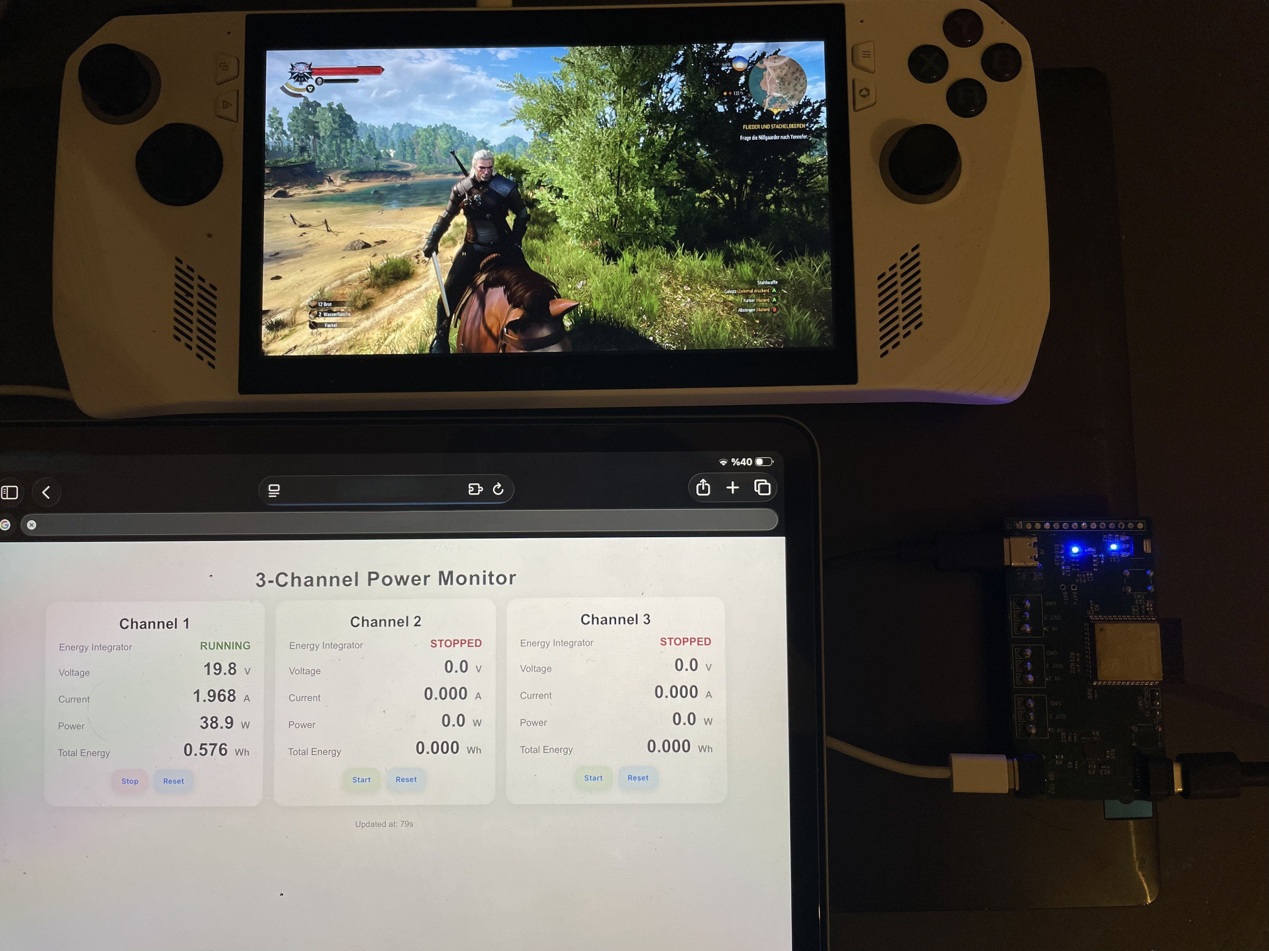
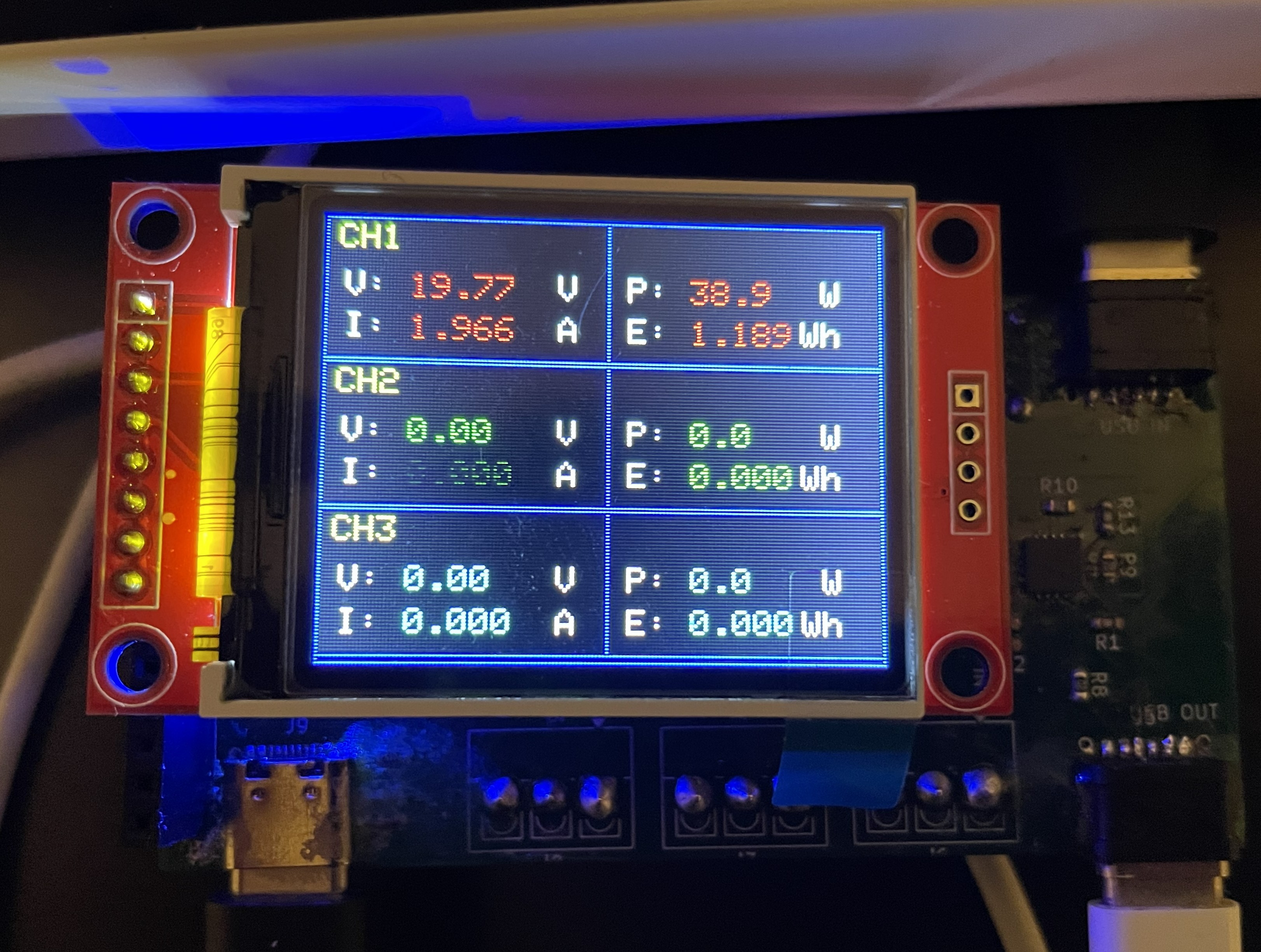
First Run Without Screen | With ST7735
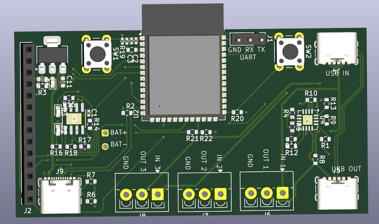
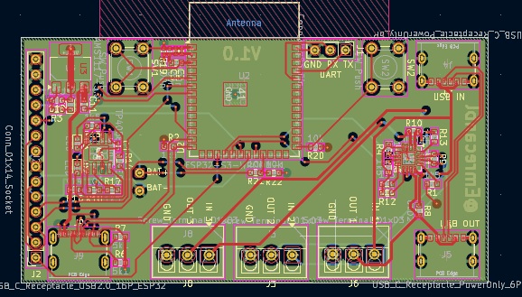
3D board render | PCB layout
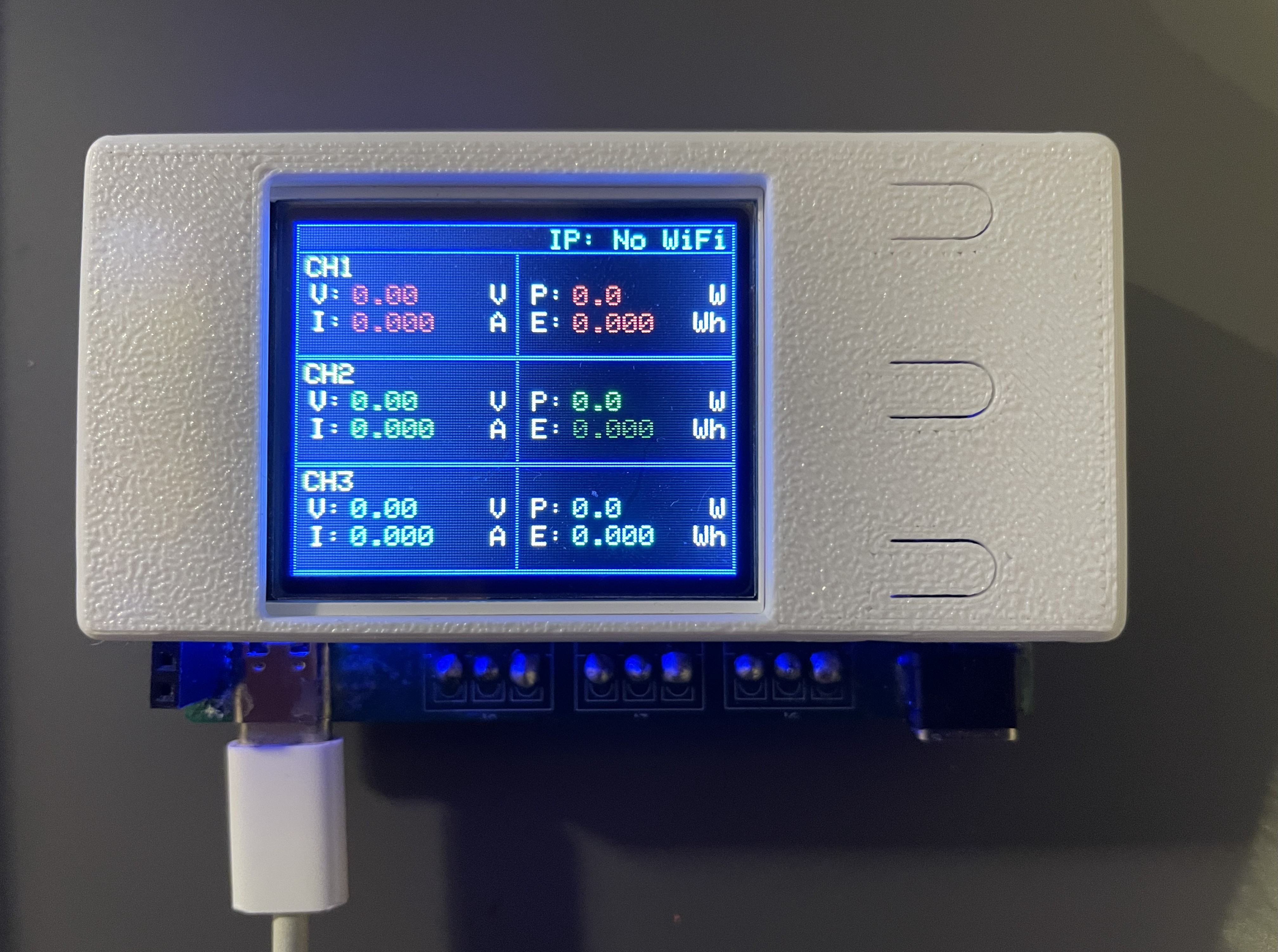 Prototype (front)
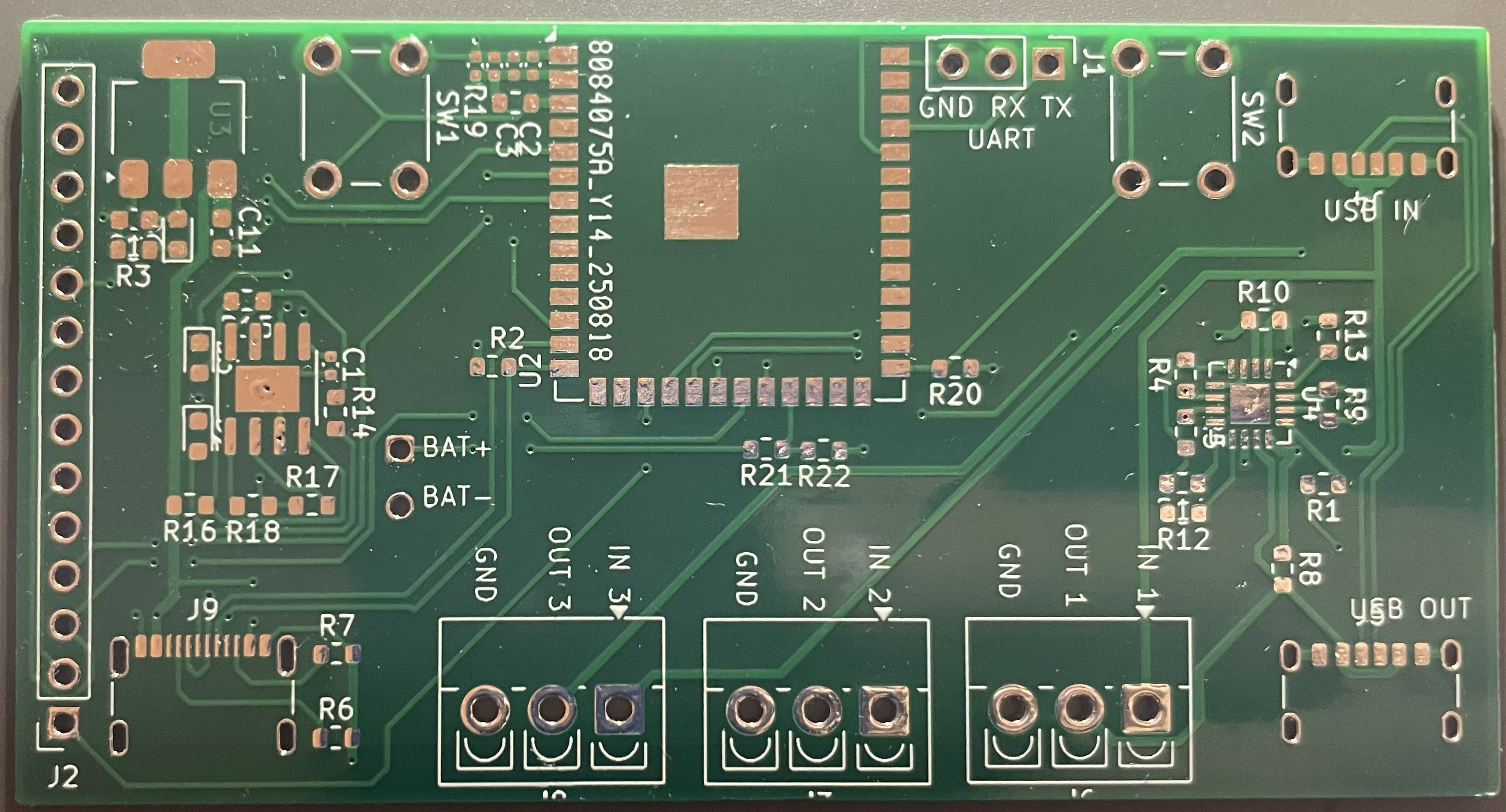
Producted PCB (first article)
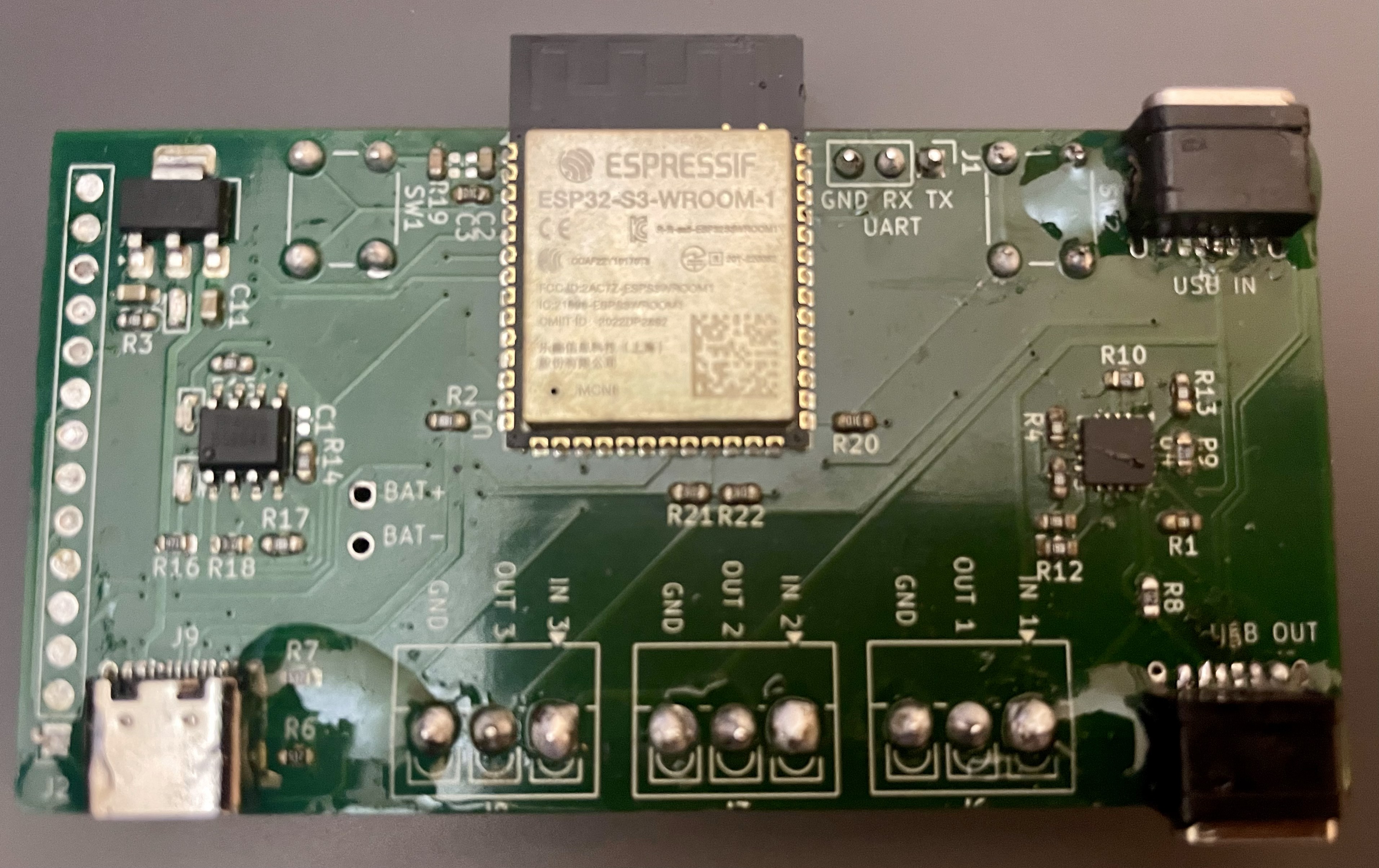
Assembled PCB
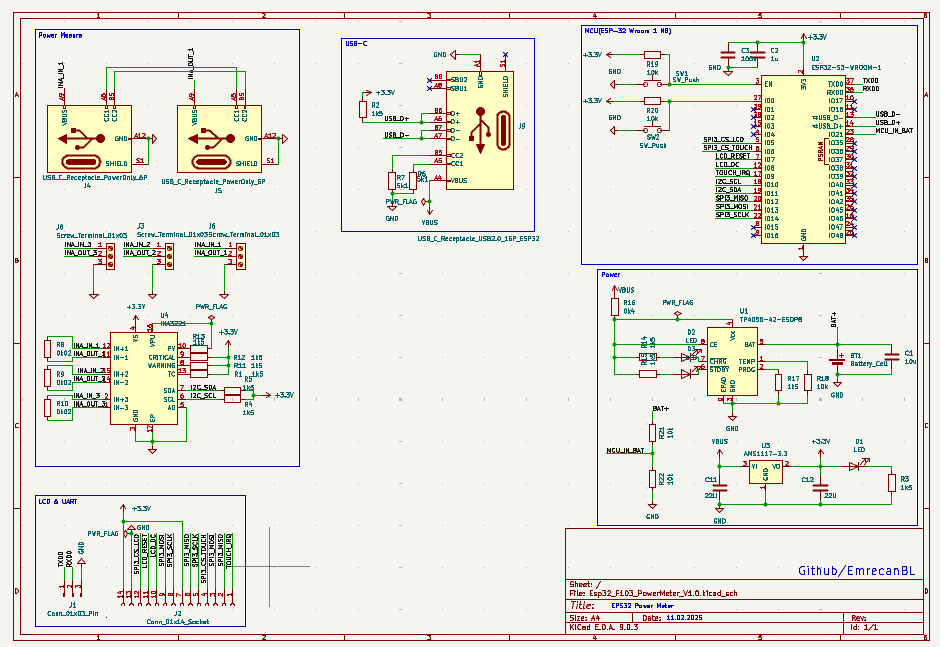
Schematic (block view)
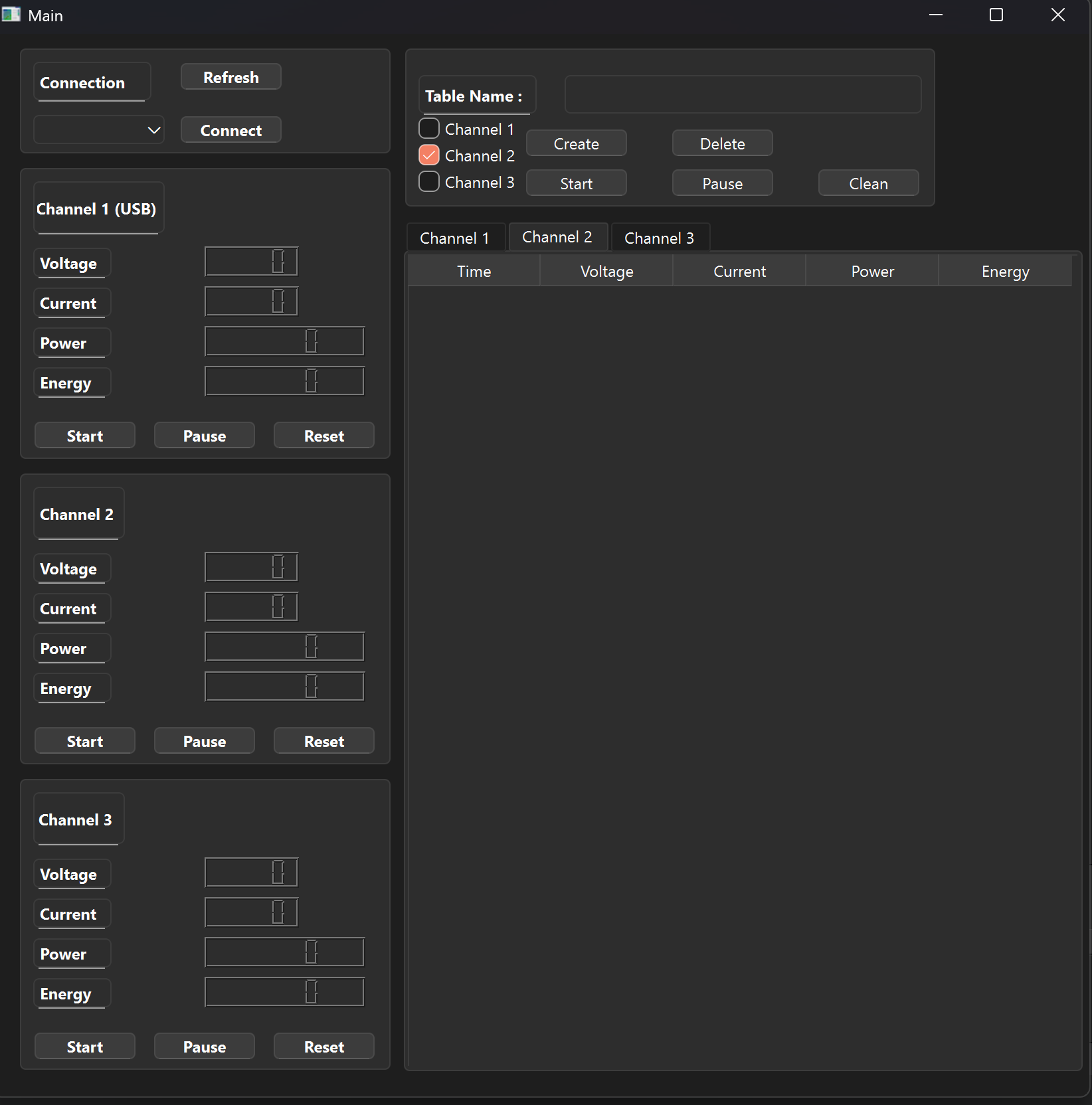
Qt Ui
USB-C IN ──┐                  ┌── USB-C OUT (pass-through)
           ├─ Shunt CH1  ─────┤
IN/OUT CH2 ├─ Shunt CH2  ─────┤──> Loads
IN/OUT CH3 ├─ Shunt CH3  ─────┘
           │
        INA3221  ── I2C ── ESP32-S3 ── SPI ── ST7735 TFT (optional)
                               ├─ (Optional) Wi‑Fi HTTP/WS
└─ USB‑CDC / UART (streaming)| Function | ESP32‑S3 Pin |
|---|---|
| I2C SDA / SCL (INA3221) | GPIO __ / __ |
| TFT (ST7735) MOSI / MISO / SCK | GPIO __ / __ / __ |
| TFT CS / DC / RST | GPIO __ / __ / __ |
| UART RX / TX | GPIO __ / __ |
| USB‑CDC | Native (S3) |
Framework: FreeRTOS
Modules:
sensor – INA3221 sampling, filtering, mAh/mWh accumulationui (optional) – minimal status pages on ST7735; device can run headlessweb – HTTP + WebSocket for live JSONusb_stream – ASCII/JSON streaming over USB‑CDC (no file logging)Example JSON (USB/Web, if enabled):
{"ch":1,"voltage":5.08,"current":1.12,"power":5.69,"mah_total":23.4,"mwh_total":118.9,"ts":1730529652}The board can measure real conversion efficiency by comparing input and output power:
/hardware
  schematic.pdf
  gerber/
/firmware
  /main
    board.h
    app_sensor.c
    app_ui_tft.c
    app_usb_stream.c
    (optional) app_web.c
  sdkconfig.defaults
/Photos
  PCB.jpg
  PCB_Model.jpg
  Prototype.jpg
  Prototype_Back1.jpg
  Prototype_Back2.jpg
  Real_PCB.jpg
  Schematic.png
/enclosure
stl/ (3D-printed case files)MIT (to be added).
| Qty | Value | Footprint | References |
|---|---|---|---|
| 11 | 1k5 | Resistor_SMD:R_0603_1608Metric | R1, R2, R3, R4, R5, R11, R12, R13, R14, R15, R17 |
| 5 | 10k | Resistor_SMD:R_0603_1608Metric | R18, R19, R20, R21, R22 |
| 3 | 0k02 | Resistor_SMD:R_0603_1608Metric | R8, R9, R10 |
| 3 | 100n | Capacitor_SMD:C_0402_1005Metric | C2, C3, C3 |
| 3 | LED | LED_SMD:LED_0603_1608Metric | D1, D2, D3 |
| 3 | Screw_Terminal_01x03 | TerminalBlock_4Ucon:TerminalBlock_4Ucon_1x03_P3.50mm_Vertical | J3, J6, J8 |
| 2 | 22U | Capacitor_SMD:C_0603_1608Metric | C11, C12 |
| 2 | 5k1 | Resistor_SMD:R_0603_1608Metric | R6, R7 |
| 2 | SW_Push | Button_Switch_THT:SW_PUSH_6mm_H4.3mm | SW1, SW2 |
| 2 | USB_C_Receptacle_PowerOnly_6P | Connector_USB:USB_C_Receptacle_GCT_USB4125-xx-x_6P_TopMnt_Horizontal | J4, J5 |
| 1 | 0k4 | Resistor_SMD:R_0603_1608Metric | R16 |
| 1 | 10u | Capacitor_SMD:C_0402_1005Metric | C1 |
| 1 | 1u | Capacitor_SMD:C_0402_1005Metric | C2 |
| 1 | AMS1117-3.3 | Package_TO_SOT_SMD:SOT-223-3_TabPin2 | U3 |
| 1 | Battery_Cell | Connector_Molex:Molex_Micro-Fit_3.0_43045-0212_2x01_P3.00mm_Vertical | BT1 |
| 1 | Conn_01x03_Pin | Connector_PinHeader_2.54mm:PinHeader_1x03_P2.54mm_Vertical | J1 |
| 1 | Conn_01x14_Socket | Connector_PinSocket_2.54mm:PinSocket_1x14_P2.54mm_Vertical | J2 |
| 1 | ESP32-S3-WROOM-1 | RF_Module:ESP32-S3-WROOM-1 | U2 |
| 1 | INA3221 | Package_DFN_QFN:Texas_RGV0016A_VQFN-16-1EP_4x4mm_P0.65mm_EP2.1x2.1mm | U4 |
| 1 | TP4056-42-ESOP8 | Package_SO:SOIC-8-1EP_3.9x4.9mm_P1.27mm_EP2.41x3.3mm_ThermalVias | U1 |
| 1 | USB_C_Receptacle_USB2.0_16P_ESP32 | Connector_USB:USB_C_Receptacle_GCT_USB4105-xx-A_16P_TopMnt_Horizontal | J9 |
EmmetGameDev/NevoltaNexusConsole
Repository for design files and code for the Nexus console.

mornepousse/Niphargus
Niphargus — a slim, indestructible wireless split keyboard. ESP32 + nRF24, wired fallback, and an emergency kit hidden behind the USB port. The successor to the Rouge-Gorge.


Simbashrek276/MonkiiBoard_Keyboards
All of our open-source keyboards, projects, and files for you to tune and make one your own.


CoryPearl/opencalc
A new and improved, better than the TI-84, open-source, graphing calculator

milovanpms/talk-e
📻 — A simple LoRa-based talkie-walkie built on ESP32, operating on the 433 MHz frequency band for long-range, low-power wireless communication.
It measures 41 × 77.8 mm and has 4 copper layers, 1.6 mm thick.
47 parts, built around the ESP32-S3-WROOM-1-N8, AMS1117-3.3 and TP4056-42-ESOP8. The full list of its parts is on this page, with links to each part's symbol and footprint where PCBKit's library has them.
From the Emrecanbl/ESP32_Power_Meter repository on GitHub, at the commit this page was made from: the board is Esp32_PowerMeter_V1.0/Esp32_F103_PowerMeter_V1.0.kicad_pcb and its schematic Esp32_PowerMeter_V1.0/Esp32_F103_PowerMeter_V1.0.kicad_sch. PCBKit opens the board in the browser, with nothing to install.
Its repository states no licence, so its author keeps all rights: ask Emrecanbl before reusing the design.