
2 layers42 × 67 mm

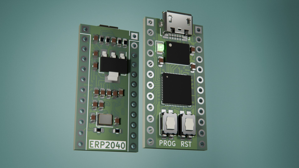
Minimal RP2040 breakout board with USB Micro-B, 16 MB QSPI flash, boot and reset buttons, and breadboard-friendly GPIO headers.
RP2040 is an open-source printed circuit board by EPSILON0-dev, from the EPSILON0-dev/RP2040-Breakout-Board repository on GitHub, published under the MIT licence. It is a 4-layer board of 15.2 × 30.5 mm with 32 parts on 52 nets, routed with 448 tracks and 71 vias.
It is built around the RP2040 and W25Q128JVSIQ. Its parts include 16 capacitors, 6 resistors, 3 ICs, 3 connectors and 2 switches. It belongs with the interfaces and adapters and microcontroller boards boards and the RP2040 boards of this library.


Minimal RP2040 breakout with USB Micro-B, 16 MB QSPI flash, and full GPIO headers in a breadboard-friendly form factor.
| Parameter | Value |
|---|---|
| MCU | RP2040 (dual-core Arm Cortex-M0+ @ up to 133 MHz) |
| Flash | 16 MB W25Q128JVS (QSPI) or compatible |
| Supply voltage | 5 V via USB Micro-B; 3.3 V via onboard AP1117-33 LDO |
| Internal 1.1 V rail | Generated by RP2040 internal LDO (VREG) |
| Clock | 12 MHz external crystal |
| USB | USB Micro-B (power + data) |
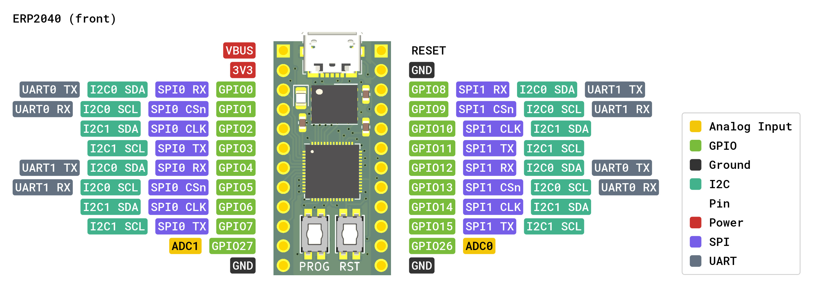
| GPIO headers | 2 × 12-pin 2.54 mm (J2, J3) |
| Status | Tested - fully functional |
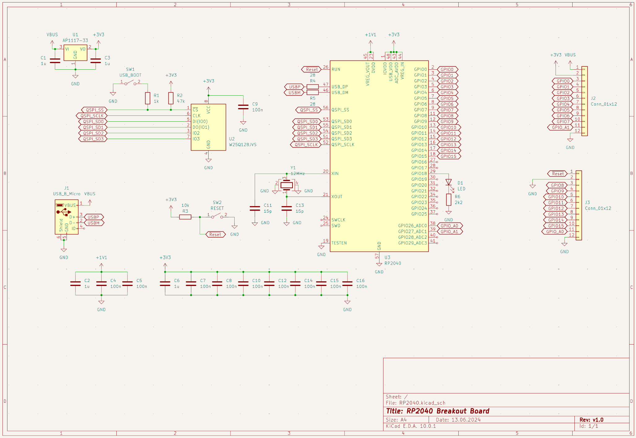
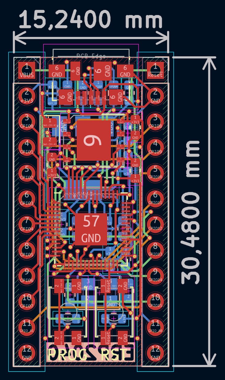
| Schematic | Board |
|---|---|
 |  |
| Control | Component | Behaviour |
|---|---|---|
| BOOT | SW1 (USB_BOOT) | Hold while connecting USB to enter USB bootloader (UF2 mode). Pulls QSPI_SS low via R1 (1 kΩ); R2 (47 kΩ) pulls QSPI_SS high normally. |
| RESET | SW2 (RESET) | Momentarily pulls RUN low. R3 (10 kΩ) holds RUN high during normal operation. |
Gerber files are in the gerber/ directory, ready to upload to JLCPCB, PCBWay, or equivalent.
Suggested fab settings:
| Setting | Value |
|---|---|
| Layers | 4 (F_Cu, In1_Cu, In2_Cu, B_Cu) |
| Thickness | 1.6 mm |
| Surface finish | HASL (lead-free) or ENIG |
# 1. Hold SW1 (BOOT button) and connect USB — board appears as RPI-RP2 mass storage
# 2. Drag and drop a UF2 firmware image
cp firmware.uf2 /media/$USER/RPI-RP2Licensed under the MIT License
| Qty | Value | Footprint | References |
|---|---|---|---|
| 10 | 100n | Capacitor_SMD:C_0603_1608Metric | C4, C5, C7, C8, C9, C10, C12, C14, C15, C16 |
| 4 | 1u | Capacitor_SMD:C_0603_1608Metric | C1, C2, C3, C6 |
| 2 | 15p | Capacitor_SMD:C_0603_1608Metric | C11, C13 |
| 2 | 28 | Resistor_SMD:R_0603_1608Metric | R4, R5 |
| 2 | Conn_01x12 | Connector_PinHeader_2.54mm:PinHeader_1x12_P2.54mm_Vertical | J2, J3 |
| 1 | 10k | Resistor_SMD:R_0603_1608Metric | R3 |
| 1 | 12MHz | Crystal:Crystal_SMD_3225-4Pin_3.2x2.5mm | Y1 |
| 1 | 1k | Resistor_SMD:R_0603_1608Metric | R1 |
| 1 | 2k2 | Resistor_SMD:R_0603_1608Metric | R6 |
| 1 | 47k | Resistor_SMD:R_0603_1608Metric | R2 |
| 1 | AP1117-33 | Package_TO_SOT_SMD:SOT-223-3_TabPin2 | U1 |
| 1 | LED | LED_SMD:LED_0805_2012Metric | D1 |
| 1 | RESET | Button_Switch_SMD:SW_SPST_EVQP2 | SW2 |
| 1 | RP2040 | Package_DFN_QFN:QFN-56-1EP_7x7mm_P0.4mm_EP3.2x3.2mm | U3 |
| 1 | USB_BOOT | Button_Switch_SMD:SW_SPST_EVQP2 | SW1 |
| 1 | USB_B_Micro | Connector_USB:USB_Micro-B_Molex_47346-0001 | J1 |
| 1 | W25Q128JVS | Package_SON:WSON-8-1EP_6x5mm_P1.27mm_EP3.4x4mm | U2 |

shanteacontrols/OpenDeck
A platform for building interactive control and sensing devices using MIDI and OSC built with Zephyr RTOS.


polpo/picogus
Emulation of ISA sound cards and CD-ROM on Raspberry Pi Pico (GUS, SB/Adlib, MPU-401, Tandy, CMS, Panasonic CD-ROM) with USB mouse/joystick support

Bastardkb/Dilemma
The Dilemma is a vertical stagger low-profile keyboard with mods.

Staacks/gbinterceptor
Capture or stream Game Boy gameplay footage via USB without modifying the Game Boy.


It measures 15.2 × 30.5 mm and has 4 copper layers, 1.6 mm thick.
32 parts, built around the RP2040 and W25Q128JVSIQ. The full list of its parts is on this page, with links to each part's symbol and footprint where PCBKit's library has them.
From the EPSILON0-dev/RP2040-Breakout-Board repository on GitHub, at the commit this page was made from: the board is RP2040.kicad_pcb and its schematic RP2040.kicad_sch. PCBKit opens the board in the browser, with nothing to install.
Its repository publishes it under the MIT licence: you may reuse it on that licence's terms (keep the author's notice, and for a copyleft licence share your changes alike).