2 layers41.2 × 46.6 mm

 JesusFreke/lalboard993
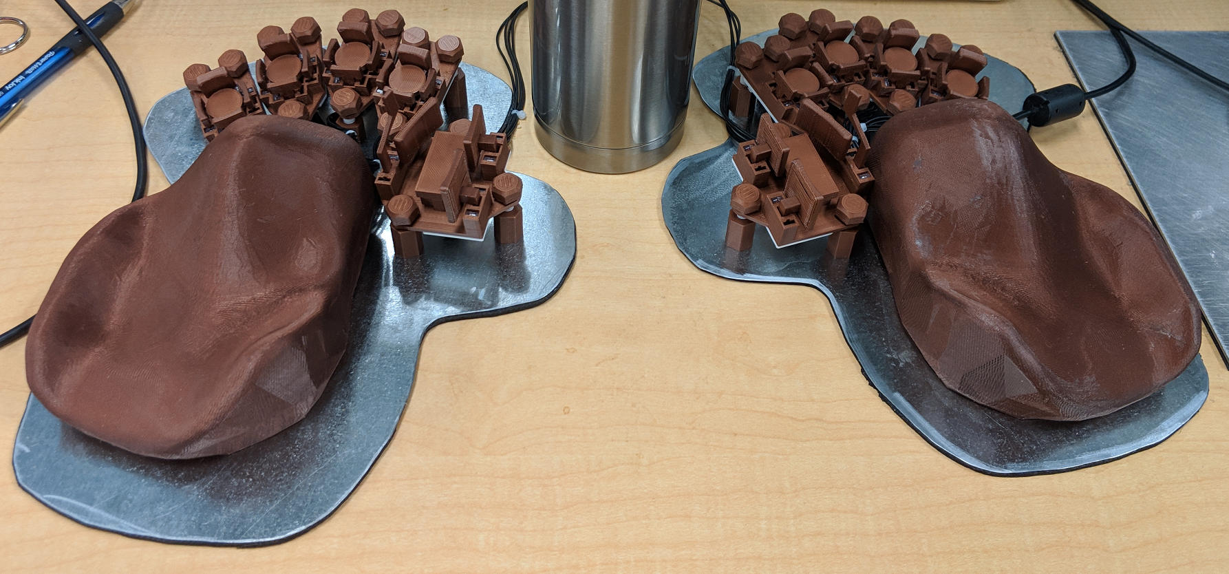
A 3D-printed keyboard inspired by the DataHand
Lalboard is an open-source printed circuit board by JesusFreke, from the JesusFreke/lalboard repository on GitHub. It is a 2-layer board of 42 × 67 mm with 65 parts on 82 nets, routed with 624 tracks and 65 vias.
It is built around the RP2040, COS724SR and W25Q128JVSIQ, with the USBLC6-2SC6, XC6220B331MR and DMG2301L-7(ES) among its other parts. Its parts include 18 capacitors, 17 resistors, 9 connectors, 7 ICs and 5 transistors. It belongs with the RP2040 boards of this library.


Online viewer for cluster assemblies:
I am a long-time user of a DataHand keyboard. With the scarcity and rising cost of second hand DataHands these days, I wanted to ensure that I always had access to a DataHand-like keyboard. And so this project was born.
The overall functionality of the lalboard is obviously heavily based on the DataHand, but I designed all of the specific key mechanisms, etc. from scratch, to be printable on a normal hobby-level FDM printer.
With my DataHand, I never felt like I could get the keys positioned quite right for my hand. So one of my primary focuses with the lalboard was adjustability. Each key cluster can be independently adjusted in all 6 degrees of freedom to some extent.
Most parts need to be printed in a very opaque PLA, but there are a few parts that don't work well in PLA which should be printed in polycarbonate or similar material, for its strength and heat resistance.
All keys use a pair of magnets to provide the clickiness and key return force, and an IR LED and phototransistor for detecting a keypress. They are all held in place only with magnets, so they are easily removable for cleaning, etc.
The feel/clickiness of the keys was another focus area. I tried to get them to feel as similar to those on a DataHand as possible. They require roughly the same amount of force, and have that same unique clicky feel due to the magnetic holding force.
The key clusters have a trio of standoffs that are designed to be mounted onto a steel sheet with magnets. Each standoff has an adjustable height, and is mounted to the key cluster via a ball socket. This provides a limited 6 degrees of freedom in adjusting the angle and position of each key cluster, in order to get it perfectly positioned for your hands.
This design uses copper traces that are cut from adhesive-backed copper tape using a vinyl cutter, and applied to the bottom of 3D-printed "pcbs" printed with polycarbonate for its excellent heat resistance during soldering. There are currently no designs for actual pcbs, but I don't think it should be difficult to do. If someone wants to tackle that, I'm happy to give pointers or otherwise help in any way I can :)
Each side of the keyboard uses an independent teensy 2.0 board, and are connected with 4 wires between them to enable communication via i2c. Only one side of the keyboard actually needs to be plugged into USB. The teensy's run a modified version of the teensyhand firmware.
The handrest was first molded for my wrist in plasticine clay, and then scanned in using the meshroom photogrammetry software. Since they were molded for my wrists specifically, I'm not sure how "one-size-fits-all" they are, or how comfortable they would be for someone else to use.
Note: This is not an officially supported Google product.
| Qty | Value | Footprint | References |
|---|---|---|---|
| 12 | 100n | Capacitor_SMD:C_0402_1005Metric | C2, C5, C6, C9, C12, C13, C14, C15, C16, C17, C19, C20 |
| 5 | 2k | Resistor_SMD:R_0402_1005Metric_Pad0.72x0.64mm_HandSolder | R9, R10, R11, R12, R13 |
| 5 | Conn_01x07 | lalboard:JST_ZH_B7B-ZR_1x07_P1.50mm_Vertical | J3, J4, J5, J6, J7 |
| 5 | DMG2301L-7 | Package_TO_SOT_SMD:SOT-23 | Q1, Q2, Q3, Q4, Q5 |
| 4 | 5.1k | Resistor_SMD:R_0402_1005Metric | R14, R15, R16, R17 |
| 4 | CBG201209U500T | Inductor_SMD:L_0805_2012Metric | FB1, FB2, FB3, FB4 |
| 2 | 1k | Capacitor_SMD:C_0402_1005Metric | R2, R3 |
| 2 | 1u | Capacitor_SMD:C_0402_1005Metric | C7, C10 |
| 2 | 27 | Capacitor_SMD:C_0402_1005Metric | R5, R6 |
| 2 | 30pF | Capacitor_SMD:C_0402_1005Metric | C8, C11 |
| 2 | COS724 | lalboard:TSSOP-14_4.4x5mm_P0.65mm | U4, U5 |
| 2 | Conn_01x18 | Connector_PinHeader_2.54mm:PinHeader_1x18_P2.54mm_Vertical | J1, J2 |
| 2 | MountingHole_Pad | MountingHole:MountingHole_3.2mm_M3_DIN965_Pad | H1, H2 |
| 2 | TYPE-C-31-M-12 | Connector_USB:USB_C_Receptacle_HRO_TYPE-C-31-M-12 | J8, J9 |
| 2 | USBLC6-2SC6 | Package_TO_SOT_SMD:SOT-23-6 | U6, U7 |
| 1 | 1.5k | Resistor_SMD:R_0402_1005Metric | R1 |
| 1 | 100k | Resistor_SMD:R_0402_1005Metric | R7 |
| 1 | 10k | Resistor_SMD:R_0402_1005Metric | R4 |
| 1 | 10u | Capacitor_SMD:C_0402_1005Metric | C1 |
| 1 | 390k | Resistor_SMD:R_0402_1005Metric | R8 |
| 1 | 4.7u | Capacitor_SMD:C_0402_1005Metric | C4 |
| 1 | Boot | lalboard:SW_TS-1187A-B-A-B | SW2 |
| 1 | Crystal_GND24 | lalboard:OSC_X322516MLB4SI | Y1 |
| 1 | RP2040 | lalboard:RP2040-QFN-56 | U2 |
| 1 | Reset | lalboard:SW_TS-1187A-B-A-B | SW1 |
| 1 | W25Q128JVS | Package_SO:SOIC-8_5.23x5.23mm_P1.27mm | U3 |
| 1 | XC6220B331MR | Package_TO_SOT_SMD:SOT-23-5 | U1 |


ZharbolatDinmukhamed/Haptic-Glove-PCB
A wrist-mounted PCB for a haptic feedback glove, developed as part of my Research Assistantship at the Tactile Laboratory, Nazarbayev University.

Isaac-Duarte/wellfed
Open firmware that runs the PETLIBRO Granary PLAF103 pet feeder on your own Wi-Fi: no cloud, no account. Early and in testing.


alph4345/test
TrinketCore puts everything a small rechargeable gadget needs on one 40 × 60 mm board, ready to order assembled from PCBWay:

enkhbold470/kicad-projects
Five KiCad 10 boards (4- and 6-layer): ESP32-S3 industrial gateway, USB-C PD bench supply, RP2040 logic analyzer, FOC motor controller, iCE40 FPGA board.

ramtuc/rp2040-logic-analyzer
RP2040 + TXU0104 16ch logic analyzer board for PulseView (sigrok-pico), 4-layer, JLCPCB PCBA

It measures 42 × 67 mm and has 2 copper layers, 1.6 mm thick.
65 parts, built around the RP2040, COS724SR, W25Q128JVSIQ and USBLC6-2SC6. The full list of its parts is on this page, with links to each part's symbol and footprint where PCBKit's library has them.
From the JesusFreke/lalboard repository on GitHub, at the commit this page was made from: the board is kicad/main_board.kicad_pcb and its schematic kicad/cluster.kicad_sch. PCBKit opens the board in the browser, with nothing to install.
Its repository states no licence, so its author keeps all rights: ask JesusFreke before reusing the design.