2 layers80 × 55.6 mm
EPSolar CAN
AugustoS97/BMS-BatterySystem
Repositorio con el diseño de un BMS y una batería como TFM
50 parts7GPL-3.0
 AugustoS97/BMS-BatterySystem7
Repositorio con el diseño de un BMS y una batería como TFM
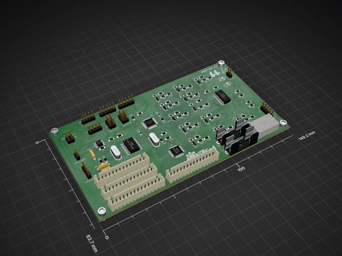
Nodo BMS 1 1 is an open-source printed circuit board by AugustoS97, from the AugustoS97/BMS-BatterySystem repository on GitHub, published under the GPL-3.0 licence. It is a 2-layer board of 149.2 × 83.7 mm with 117 parts on 139 nets, routed with 1,767 tracks and 107 vias.
It is built around the ATMEGA328P-PU, TJA1050T/CM and ADG731BCP, with the MP2307DN-Z and BSS308PE among its other parts. Its parts include 46 resistors, 24 capacitors, 15 connectors, 12 transistors and 6 ICs. It belongs with the power and interfaces and adapters boards and the AVR (ATmega, ATtiny) boards of this library.


Repositorio con el diseño de un BMS y una batería como Trabajo de Fin de Máster.
El presente Trabajo Fin de Máster consiste en el diseñado y fabricación de un Sistema de Gestión de Batería (BMS), así como una batería modular configurable a diferentes tensiones y capacidades, con el objetivo de poder alimentar sistemas electrónicos aislados como los dispositivos de capturas de índices de significación eco-acústicos. Se ha llevado a cabo el diseño electrónico de los diferentes módulos que forman el sistema de alimentación y gestión así como el cálculo y diseño de la batería a partir de celdas de ion-litio y su estructura mecánica. Para poder alimentar dicho sistema se ha dimensionado una posible instalación generadora, empleando energía fotovoltaica. Finalmente, se ha realizado la fabricación de los distintos elementos, tanto mecánicos como electrónicos, y el desarrollo software de las diferentes herramientas necesarias para la configuración del BMS, la captura y el análisis de los datos generados. Por último, se han propuesto y analizado diferentes aplicaciones, además de la mencionada como objetivo principal del proyecto, para este sistema de BMS y acumulador.
In the present Master’s Degree Final Project, a Battery Management System (BMS) has been designed and manufactured, as well as a modular battery configurable at different voltages and capacities, with the aim of being able to power isolated electronic systems such as devices for capturing eco-acoustic significance indexes. The electronic design of the different modules that make up the power supply and management system has been carried out, as well as the calculation and design of the battery based on lithium-ion cells and its mechanical structure. In order to be able to supply this system, a possible generating installation has been dimensioned, using photovoltaic energy. Finally, the manufacture of the different elements, both mechanical and electronic, and the software development of the different tools necessary for the configuration of the BMS and the capture and analysis of the data generated have been carried out. Finally, different applications have been proposed and analysed, in addition to the one mentioned as the main objective of the project, for this BMS and accumulator system.


El diagrama de bloques del sistema de alimentación y la batería es el siguiente:

La batería diseñada es la siguiente:

Los módulos electrónicos diseñados son los siguientes:


| Qty | Value | Footprint | References |
|---|---|---|---|
| 13 | 100R | Resistor_SMD:R_1206_3216Metric_Pad1.30x1.75mm_HandSolder | R9, R12, R13, R14, R15, R16, R17, R18, R19, R20, R21, R22, R23 |
| 12 | 10R, 2W | Resistor_SMD:R_1206_3216Metric_Pad1.30x1.75mm_HandSolder | R28, R29, R30, R31, R36, R37, R38, R39, R44, R45, R46, R47 |
| 12 | 10n | Resistor_SMD:R_1206_3216Metric_Pad1.30x1.75mm_HandSolder | C13, C14, C15, C16, C17, C18, C19, C20, C21, C22, C23, C24 |
| 12 | 1k | Resistor_SMD:R_0805_2012Metric_Pad1.15x1.40mm_HandSolder | R24, R25, R26, R27, R32, R33, R34, R35, R40, R41, R42, R43 |
| 12 | BSS308PE | Package_TO_SOT_SMD:SOT-23 | Q2, Q3, Q4, Q5, Q6, Q7, Q8, Q9, Q10, Q11, Q12, Q13 |
| 4 | MountingHole | MountingHole:MountingHole_3.2mm_M3 | H1, H2, H3, H4 |
| 3 | 100n | Resistor_SMD:R_1206_3216Metric_Pad1.30x1.75mm_HandSolder | C1, C4, C11 |
| 3 | 120R | Resistor_THT:R_Axial_DIN0207_L6.3mm_D2.5mm_P7.62mm_Horizontal | R2, R7, R8 |
| 3 | 1u | Resistor_SMD:R_1206_3216Metric_Pad1.30x1.75mm_HandSolder | C5, C6, C8 |
| 2 | 27pF | Resistor_SMD:R_1206_3216Metric_Pad1.30x1.75mm_HandSolder | C2, C3 |
| 2 | Jumper_3_Open | Jumper:SolderJumper-3_P1.3mm_Open_Pad1.0x1.5mm | JP1, JP2 |
| 1 | 100nF | Resistor_SMD:R_1206_3216Metric_Pad1.30x1.75mm_HandSolder | C12 |
| 1 | 100nF | Resistor_SMD:R_1206_3216Metric | C25 |
| 1 | 10K | Resistor_SMD:R_0805_2012Metric_Pad1.15x1.40mm_HandSolder | R1 |
| 1 | 10k | Resistor_SMD:R_1206_3216Metric_Pad1.30x1.75mm_HandSolder | R10 |
| 1 | 10k | Resistor_SMD:R_0805_2012Metric_Pad1.15x1.40mm_HandSolder | R3 |
| 1 | 12-22 pF | Resistor_SMD:R_1206_3216Metric_Pad1.30x1.75mm_HandSolder | C9 |
| 1 | 12-22pF | Resistor_SMD:R_1206_3216Metric_Pad1.30x1.75mm_HandSolder | C10 |
| 1 | 16MHz | SmartBMS:Crystal_HC49-4H_Vertical | Y2 |
| 1 | 1M | Resistor_SMD:R_1206_3216Metric | R48 |
| 1 | 1k | Resistor_SMD:R_1206_3216Metric_Pad1.30x1.75mm_HandSolder | R11 |
| 1 | 5k | Resistor_SMD:R_1206_3216Metric_Pad1.42x1.75mm_HandSolder | R4 |
| 1 | 8MHz | SmartBMS:Crystal_HC49-4H_Vertical | Y1 |
| 1 | ADG731 | Package_QFP:TQFP-48_7x7mm_P0.5mm | U1 |
| 1 | ATmega328P-PU | SmartBMS:TQFP-32_7x7mm_P0.8mm | U4 |
| 1 | Conn_ADC | SmartBMS:PinHeader_1x05_P2.54mm_Vertical | J1 |
| 1 | Conn_Batt | SmartBMS:JST_XH_B14B-XH-A_1x14_P2.50mm_Vertical | J9 |
| 1 | Conn_CAN | SmartBMS:PinHeader_1x02_P2.54mm_Vertical | J3 |
| 1 | Conn_CAN_2 | Connector_PinSocket_2.54mm:PinSocket_2x02_P2.54mm_Vertical | J4 |
| 1 | Conn_FTDI | SmartBMS:PinHeader_2x03_P2.54mm_Vertical | J8 |
| 1 | Conn_GPIO | SmartBMS:PinHeader_1x05_P2.54mm_Vertical | J13 |
| 1 | Conn_GPIO2 | SmartBMS:PinHeader_1x05_P2.54mm_Vertical | J2 |
| 1 | Conn_I2C_1 | SmartBMS:PinHeader_1x04_P2.54mm_Vertical | J10 |
| 1 | Conn_I2C_2 | SmartBMS:PinHeader_1x04_P2.54mm_Vertical | J11 |
| 1 | Conn_ICSP | SmartBMS:PinHeader_2x03_P2.54mm_Vertical | J14 |
| 1 | Conn_T1-T10 | SmartBMS:JST_XH_B14B-XH-A_1x14_P2.50mm_Vertical | J6 |
| 1 | Conn_T11-T20 | SmartBMS:JST_XH_B14B-XH-A_1x14_P2.50mm_Vertical | J7 |
| 1 | Conn_T21-T32 | SmartBMS:JST_XH_B14B-XH-A_1x14_P2.50mm_Vertical | J5 |
| 1 | Conn_UART | SmartBMS:PinHeader_1x04_P2.54mm_Vertical | J12 |
| 1 | LOGO | logos_pcb:logo_ull | G*** |
| 1 | LOGO | logos_pcb:logo_augusto | G*** |
| 1 | LOGO | logos_pcb:logo_grupo | G*** |
| 1 | LTC6804-2 | SmartBMS:SSOP-48_5.3x12.8mm_P0.5mm | U5 |
| 1 | MCP2515-xSO | Package_SO:SOIC-18W_7.5x11.6mm_P1.27mm | U2 |
| 1 | MP2307 | SmartBMS:MP2307 | U6 |
| 1 | TJA1050T | Package_SO:SOIC-8_3.9x4.9mm_P1.27mm | U3 |
| 1 | V+_EXT | SmartBMS:PinHeader_1x02_P2.54mm_Vertical | J15 |
| 1 | fuse 0,5 A | Fuse:Fuseholder_Cylinder-5x20mm_Stelvio-Kontek_PTF78_Horizontal_Open | F2 |
| 1 | fuse 1A | Fuse:Fuseholder_Cylinder-5x20mm_Stelvio-Kontek_PTF78_Horizontal_Open | F1 |
The 116 most common of 117 parts.
AugustoS97/BMS-BatterySystem
Repositorio con el diseño de un BMS y una batería como TFM

AugustoS97/BMS-BatterySystem
Repositorio con el diseño de un BMS y una batería como TFM

AugustoS97/CanBus-Radio-VAG
CANBUS PCB to control original functions of VAG (VW, SKODA, SEAT, AUDI) cars (such us original DSP and other functions).

Tincho1286/Synchra
Synchra reúne el desarrollo de un controlador electrónico de velocidad (ESC) sensorless basado en Arduino/ATmega328, su electrónica asociada y un sistema de control remoto.


JeyRunner/actonator
3D printable robot actuator with belt-driven gearbox and custom FOC driver board.

dremeier/Arduino-JK-BMS-To-Pylontech-CAN-PCB
PCB and Case for the Arduino JK-BMS To Pylontech CAN converter


monsterzack5/AutoMato
A Car based automation framework, fully integrated with Node-Red!

It measures 149.2 × 83.7 mm and has 2 copper layers, 1.6 mm thick.
117 parts, built around the ATMEGA328P-PU, TJA1050T/CM, ADG731BCP and MP2307DN-Z. The full list of its parts is on this page, with links to each part's symbol and footprint where PCBKit's library has them.
From the AugustoS97/BMS-BatterySystem repository on GitHub, at the commit this page was made from: the board is Diseno-Electronico/SmartBMS/Nodo_BMS_1_1.kicad_pcb. PCBKit opens the board in the browser, with nothing to install.
Its repository publishes it under the GPL-3.0 licence: you may reuse it on that licence's terms (keep the author's notice, and for a copyleft licence share your changes alike).