2 layers65 × 100 mm
Receiver
Arshsingh1602/Smart-Irrigation-System
This is our project of SIH 2024 in which we developed a smart irrigation system that can be used to control the under and overuse of water in the feild of farmer.
26 partsMIT
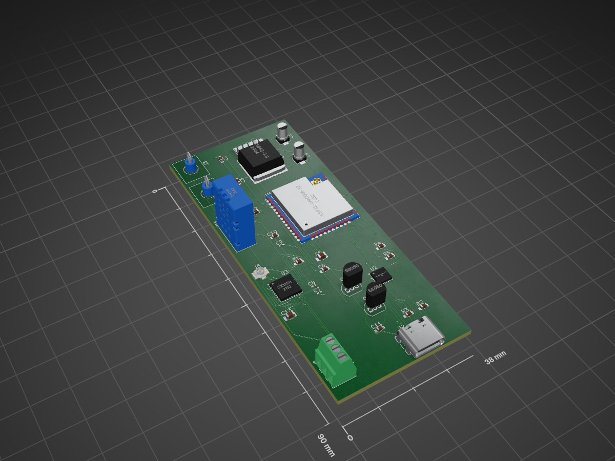
 Arshsingh1602/Smart-Irrigation-System
This is our project of SIH 2024 in which we developed a smart irrigation system that can be used to control the under and overuse of water in the feild of farmer. This is a transmitter and receiver code that uses LoRa technology to communicate and uses firebase as a cloud and to store the data. This is only the hardware coding of it.
SIH Smart Irrigation System is an open-source printed circuit board by Arshsingh1602, from the Arshsingh1602/Smart-Irrigation-System repository on GitHub, published under the MIT licence. It is a 2-layer board of 38 × 90 mm with 30 parts on 82 nets, routed with 524 tracks and 49 vias.
It is built around the ESP32-WROOM-32U, SX1278 and DHT11, with the LM2596S-3.3 and S8050 among its other parts. Its parts include 13 capacitors, 5 resistors, 5 ICs, 5 connectors and 2 transistors. It belongs with the radio and wireless boards and the ESP32 boards of this library.


This project is a transmitter-receiver duo using the LoRa communication protocol that helps us to revolutionize the agriculture industry by advancing the Smart Irrigation System. The transmitter acts as the node that transmits the data, and the receiver acts as the central node to receive that data and communicate it further, and process it.
Features of the project include:
| Component | Quantity | Description / Link |
|---|---|---|
| ESP32 Dev Board | 2 | WiFi + Bluetooth enabled |
| SX1278 LoRa Module | 2 | 433MHz |
| Soil Moisture Sensor | 1 | Capacitive type |
| MCP9808 Temp Sensor/DHT11 | 1 | Temperature sensor |
| Water Valve (12V) | 1 | Controlled via relay |
| Relay Module | 1 | For switching valve |
| Power Supply (12V, 5V) | 1 each | For sensors and motors |
To understand how the project works, we must understand some things first:
Soil Moisture Content: The amount of water present in the soil, usually measured as a percentage. It can be volumetric (by volume) or gravimetric (by weight). Field Capacity (FC): The maximum moisture level that soil retains after excess water has drained. It represents the ideal moisture for plant growth. Wilting Point (WP): The minimum moisture level at which plants begin to wilt due to lack of available water. Permanent Wilting Point (PWP): A critical level where plants can no longer recover, even if water is reintroduced. Available Water Content (AWC): The difference between field capacity and wilting point. It indicates the water range that plants can effectively use.
AWC = Field Capacity − Wilting Point
Saturation Point: When all soil pores are filled with water. Beyond this point, water drainage occurs, and root oxygen is limited. Soil Water Potential (Tension): Indicates how tightly water is held in soil. Measured in kPa, where:
0 kPa = Saturated soil
−33 kPa ≈ Field capacity
−1500 kPa ≈ Wilting point
Soil Texture: Affects water retention. Sandy soils drain quickly, while clay holds more water.
The soil moisture sensor in the transmitter checks the water content in the soil, sends analogue data to the ESP 32, which takes the analogue data and converts it to scientifically accurate values and parameters. These parameters are defined above. There are various ways to program out AI/ML to find out what equation best fits the analogue data, which can be calculated based on heavy experimentation and data collection. The temperature sensor also sends its data to the ESP, and from there, the microcontroller takes the help of the LoRa module to transmit that data to the receiver that is kept far away from the transmitter. The main motto for this transmission is to have data collection and transmission from places in the field where the is no internet connection. One receiver can handle multiple transmitters varying from 4-10(max).
The receiver side is connected to the internet with wifi and can receive the transmitter data, and with the help of an internet connection, sends data to the cloud server that stores data according to the transmitter number, for further analysis. The main role of the receiver is to upload the transmitter's data and also send the data from the cloud back to the respective transmitters in order to control the relay, which controls the valve for irrigation.
The ML model takes the temperature data and the soil moisture sensor, combined with the local humidity and rainfall fetched from the API. The model predicts when to command the specific valve to turn on, depending on the future rainfall predictions and the current status of the soil moisture. For example, if the soil moisture is below the critical level, then the part of the land should be irrigated immediately. But if the soil moisture is low, but the algorithm predicts that rainfall is expected in a few days, then, depending upon the average evaporation rate and the humidity, only a specific amount of water will be released such that the rainfall replenishes the remaining required amount. This way it saves water.
Dependencies / Libraries:
Challenges:
Future Scope:
This is a public repo licensed under the MIT license. Users are obliged to reference/credit me(Arsh Singh) when copying the project or using/updating this project.
Made by Arsh Singh
| Qty | Value | Footprint | References |
|---|---|---|---|
| 4 | 0.1uF | Capacitor_SMD:C_0603_1608Metric | C2, C3, C10, C12 |
| 3 | 10kR | Capacitor_SMD:C_0603_1608Metric_Pad1.08x0.95mm_HandSolder | R1, R4, R5 |
| 3 | 10uF | Capacitor_SMD:C_0201_0603Metric_Pad0.64x0.40mm_HandSolder | C7, C8, C9 |
| 2 | 100uF | Capacitor_SMD:CP_Elec_3x5.3 | C1, C4 |
| 2 | 1uF | Capacitor_SMD:C_0805_2012Metric_Pad1.18x1.45mm_HandSolder | C5, C13 |
| 2 | 5.21kR | Capacitor_SMD:C_0603_1608Metric_Pad1.08x0.95mm_HandSolder | R2, R3 |
| 2 | S8050 | Package_TO_SOT_THT:TO-92_Inline | Q1, Q2 |
| 2 | Screw_Terminal_01x01 | TerminalBlock_MetzConnect:TerminalBlock_MetzConnect_360271_1x01_Horizontal_ScrewM3.0_Boxed | J3, J4 |
| 1 | 10nF | Capacitor_SMD:C_0603_1608Metric_Pad1.08x0.95mm_HandSolder | C11 |
| 1 | 1uF | Capacitor_SMD:C_0603_1608Metric_Pad1.08x0.95mm_HandSolder | C6 |
| 1 | CP2102N-Axx-xQFN24 | Package_DFN_QFN:QFN-24-1EP_4x4mm_P0.5mm_EP2.6x2.6mm | U2 |
| 1 | DHT11 | Sensor:Aosong_DHT11_5.5x12.0_P2.54mm | U5 |
| 1 | ESP32-WROOM-32U | RF_Module:ESP32-WROOM-32U | U1 |
| 1 | LM2596S-3.3 | Package_TO_SOT_SMD:TO-263-5_TabPin3 | U4 |
| 1 | SX1278 | Package_DFN_QFN:QFN-28-1EP_6x6mm_P0.65mm_EP4.8x4.8mm | U3 |
| 1 | Screw_Terminal_01x03 | TerminalBlock_Phoenix:TerminalBlock_Phoenix_MPT-0,5-3-2.54_1x03_P2.54mm_Horizontal | J1 |
| 1 | U.FL-R-SMT_01_ | UFL CONNECTOR:HRS_U.FL-R-SMT_01_ | J5 |
| 1 | USB_C_Receptacle_USB2.0_16P | Connector_USB:USB_C_Receptacle_GCT_USB4105-xx-A_16P_TopMnt_Horizontal | J2 |
Arshsingh1602/Smart-Irrigation-System
This is our project of SIH 2024 in which we developed a smart irrigation system that can be used to control the under and overuse of water in the feild of farmer.

TanujRai14/Sat_pcb_design
This repository contains the PCB design files and documentation for a Can Satellite, featuring multiple environmental and orientation sensors, power management, and wireless communication capabilities.


Pritika-2024/Lora_Communication_based_real_time_tracking
A real-time wireless tracking system using an STM32-based transmitter integrated with GPS and LoRa modules, and an ESP32-based receiver with LoRa communication.

Kmshanley/PicoSat-Initiative
The pocket cube standard requires satellites to be 5x5x5cm and under 250 grams. Upon completion of this Wentworth PicoSat it will become one of the smallest satellites capable of high resolution imagery from LEO.

AchyuthaU24/ble-pcb-kicad
BLE module PCB designed in KiCad - schematic, layout and BOM

Alfaa123/Arduino-Thermostat
This is a project to create a Arduino powered home thermostat. Version 1 PCB schematic and design is complete.

dlmuschamp/ESP32IEMPack
A repo to store my code and schematics for a custom wireless IEM pack built using 2 ESP32s and some TFT displays.
It measures 38 × 90 mm and has 2 copper layers, 1.6 mm thick.
30 parts, built around the ESP32-WROOM-32U, SX1278, DHT11 and LM2596S-3.3. The full list of its parts is on this page, with links to each part's symbol and footprint where PCBKit's library has them.
From the Arshsingh1602/Smart-Irrigation-System repository on GitHub, at the commit this page was made from: the board is Transmitter(PCB)/SIH Smart Irrigation System.kicad_pcb and its schematic Receiver(PCB)/Receiver.kicad_sch. PCBKit opens the board in the browser, with nothing to install.
Its repository publishes it under the MIT licence: you may reuse it on that licence's terms (keep the author's notice, and for a copyleft licence share your changes alike).