2 layers100 × 70 mm
Telemetry pcb
supermileage/telemetry-pcb
Printer Circuit Board design for Telemetry module + voltage regulators for 12v and 5v rails
62 parts1
 0x007E/oft1
Optical Fibre Transceiver
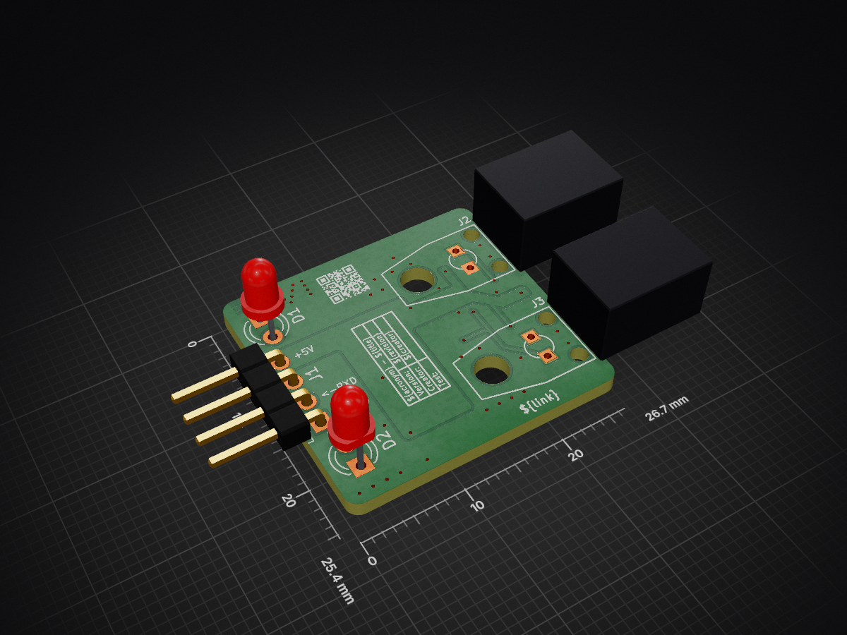
Oft is an open-source printed circuit board by 0x007E, from the 0x007E/oft repository on GitHub. It is a 2-layer board of 26.7 × 25.4 mm with 28 parts on 19 nets, routed with 80 tracks and 47 vias.
It is built around the IF-D92, IF-E91A and NE555D, with the SN74LVC1G14DBV among its other parts. Its parts include 9 resistors, 8 capacitors, 4 ICs, 3 diodes and 3 connectors. It belongs with the radio and wireless and interfaces and adapters boards of this library.


OFT - Optical Fibre TransceiverThe OFT project is based on a fibre optic transmitter an receiver (FB104). The transmitter is based on a high-output medium-speed infrared LED while the transceiver is built on a high-sensitivity NPN phototransistor. Both are housed in a connector-less style plastic fiber optic package. The transmitter has a typical peak wavelength of 930nm. The bandwith of the receiver is between 400nm to 1100nm. The maximum photosensitivity is around 870nm. The receiver and transmitter is connected with an RX and TX LED over a NE555 timer circuit to indicate if a data transmission occurrs.
Note that the
IF-D92is suitable for digital data links at rates up to20kbps!
| Experience | Level |
|---|---|
| Soldering | |
| Mechanical |
| Type | File | Description |
|---|---|---|
| Schematic | pdf / cadlab | Schematic files |
| Board | pdf / cadlab | Board file |
| Drill | Drill file | |
| BoM | xlsx / html | Bill of Material as Excel/interactive HTML |
| PCB | zip / tar | KiCAD/Gerber/BoM/Drill files |
| Mechanical | zip / tar | FreeCAD/Housing and PCB (STEP/STL) files |
There are two parts of the hardware. The pcb and the housing of the OFT. The pcb is created with KiCAD and the housing with FreeCAD. All files are built with github actions so that they are ready for a production environment. The housing is printed with a 3D-printer (Dremel 3D40).
The circuit board is populated on both sides (Top, Bottom). The best way for soldering the SMD components is within a vapor phase soldering system and for the THT components with a standard soldering system.


The housing has a tolerance of 0.2mm on each side of the case. So the pcb should fit perfectly in the housing. The tolerance can be modified with FreeCAD in the Parameter Spreadsheet.
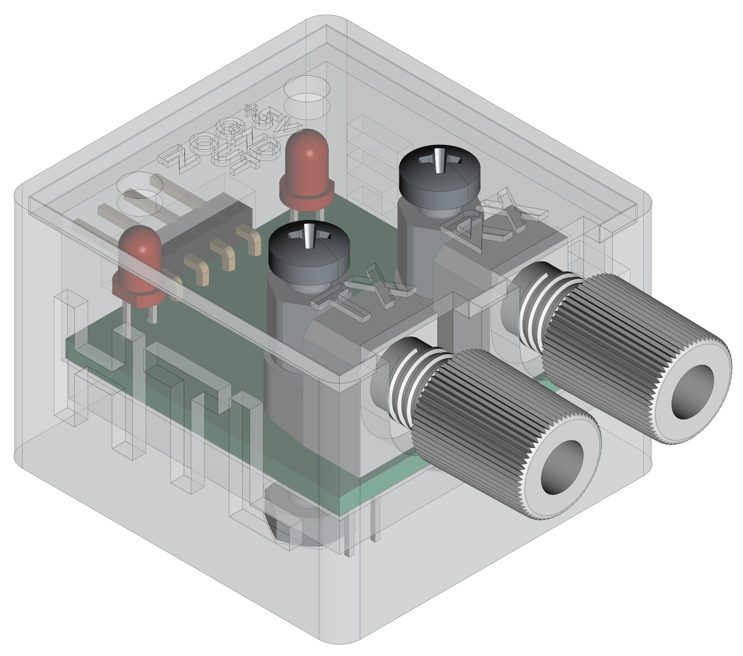
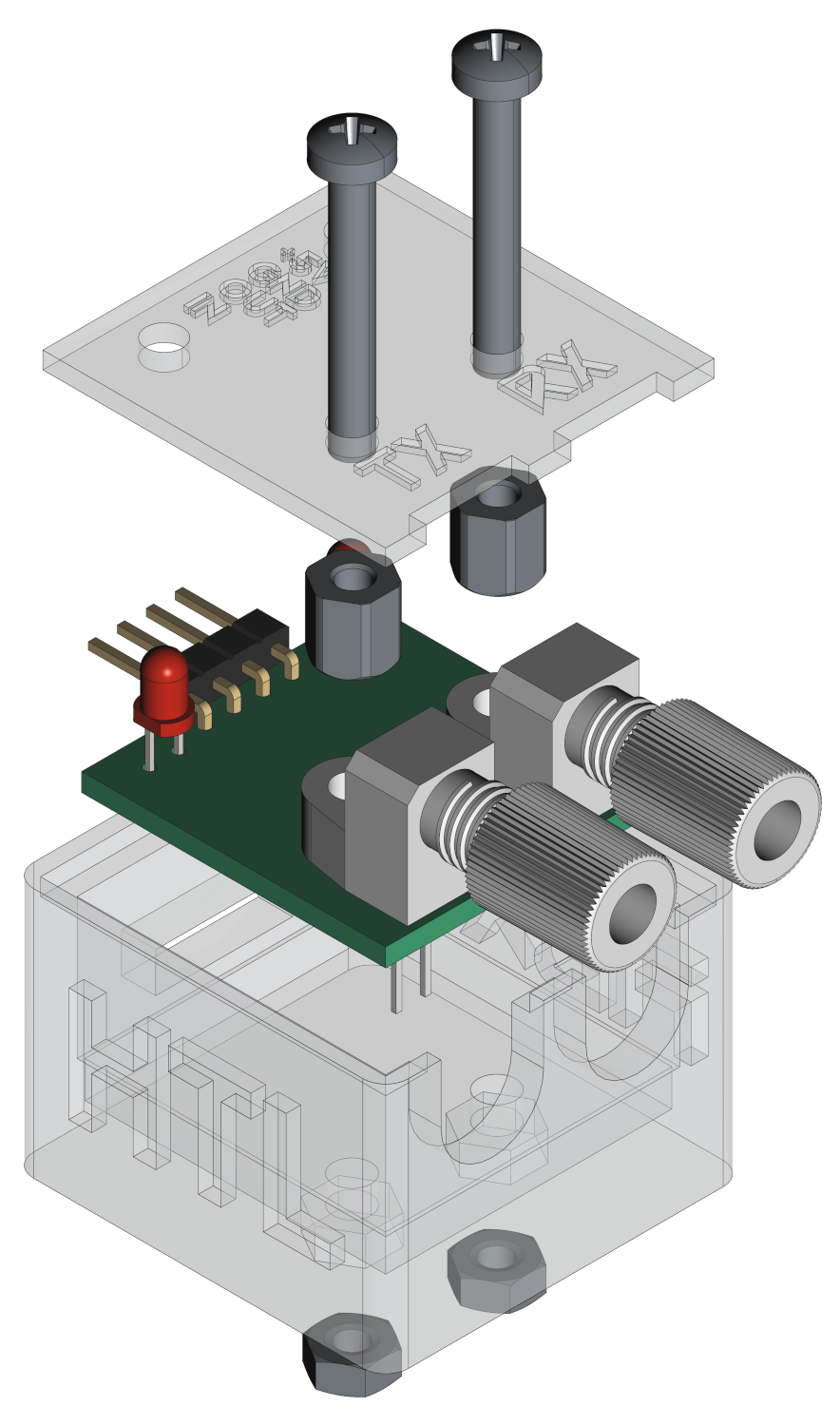
The OFT is powerd with 5V. The RX pin serves as an output and stores the received data at the output so that it can be read by the device. The TX pin servs as an input and sends the received data at the input over the fibre channel. The levels of both pins are LOW = 0V and HIGH = 5V.
#
#                                      +----------------+      +---------------------+
#                                      |    U       +---+---+  |                     |
#                                      |    S       |  USB  |--+ +-----------------+ |
#                                      |    B       +---+---+  | | TeraTerm        | |
#              +-------------+         |    /           |      | | ~~~~~~~~        | |
#              |      O      |         |    U           |      | | ~~~~~           | |
#            +--+--+  F   +--+--+   +--+--+ A           |      | | ~~~~~~~~~~~~    | |
#      L +---+ ORX |  T   | VCC +---+ VCC | R           |      | |                 | |
#      O |   +--+--+      | GND +---+ GND | T  +-+      |      | +-----------------+ |
#      O |      |         +-----+   +-----+   / /       |      |                     |
#      P |   +--+--+      | RXD +---+ RXD | +-+-+-+-----+      | Computer            |
#      B +---+ OTX |      | TXD +---+ TXD | | 5V  | 3V3 |      |                     |
#      A     +--+--+      +--+--+   +--+--+ +-----+-----+      +---------------------+
#      C       |             |
#      K       +-------------+
#
The maximum baudrate should be about
~19200bps!
| Type | Link | Description |
|---|---|---|
| IF-E10 | Optical fibre receiver and transmitter | |
| NE555 | Universal timer and oscillator | |
| KiCAD | web | KiCAD project page |
| FreeCAD | web | FreeCAD project page |
R. GAECHTER
| Qty | Value | Footprint | References |
|---|---|---|---|
| 4 | 100n | Capacitor_SMD:C_1206_3216Metric | C1, C2, C3, C4 |
| 2 | 10k | Resistor_SMD:R_1206_3216Metric | R7, R8 |
| 2 | 1n | Capacitor_SMD:C_1206_3216Metric | C5, C7 |
| 2 | 220k | Resistor_SMD:R_1206_3216Metric | R4, R6 |
| 2 | 330 | Resistor_SMD:R_1206_3216Metric | R5, R9 |
| 2 | 470n | Capacitor_SMD:C_1206_3216Metric | C6, C8 |
| 2 | NE555D | Package_SO:SOIC-8_3.9x4.9mm_P1.27mm | U5, U6 |
| 2 | SN74LVC1G14 | Package_TO_SOT_SMD:SOT-353_SC-70-5 | U1, U4 |
| 1 | 100k | Resistor_SMD:R_1206_3216Metric | R3 |
| 1 | 1k | Resistor_SMD:R_1206_3216Metric | R1 |
| 1 | 220 | Resistor_SMD:R_1206_3216Metric | R2 |
| 1 | 5V6 | Diode_SMD:D_MiniMELF | D3 |
| 1 | Conn_01x04_Pin | Connector_PinHeader_2.54mm:PinHeader_1x04_P2.54mm_Horizontal | J1 |
| 1 | Green | LED_THT:LED_D3.0mm | D2 |
| 1 | IF-D92 | Fiber_Optic:IF-D92 | J2 |
| 1 | IF-E91A | Fiber_Optic:IF-E91A | J3 |
| 1 | QR | Images:QR_0x007e_very_small | FID1 |
| 1 | Yellow | LED_THT:LED_D3.0mm | D1 |
It measures 26.7 × 25.4 mm and has 2 copper layers, 1.6 mm thick.
28 parts, built around the IF-D92, IF-E91A, NE555D and SN74LVC1G14DBV. The full list of its parts is on this page, with links to each part's symbol and footprint where PCBKit's library has them.
From the 0x007E/oft repository on GitHub, at the commit this page was made from: the board is pcb/OFT.kicad_pcb and its schematic pcb/OFT.kicad_sch. PCBKit opens the board in the browser, with nothing to install.
Its repository states no licence, so its author keeps all rights: ask 0x007E before reusing the design.
supermileage/telemetry-pcb
Printer Circuit Board design for Telemetry module + voltage regulators for 12v and 5v rails

agranlund/raven
Homemade MC68060 + DSP56303 Atari-compatible computer. Hardware, firmware, and software stack

filmolino/SlideScanner
The Filmolino SlideScanner is a device that makes it easy to scan slides in magazines fully automated using a modified slide projector and a digital camera.


mijuc/CCFL2LED
Hi! I'm working on the R&D side of the Поново project. Through our initiative, where we upcycle old electronic devices in exchange for tree seedlings, we’ve noticed that LCD monitors are among the most common items…


