4 layers144.1 × 93.3 mm

 mijuc/CCFL2LED7
Hi! I'm working on the R&D side of the Поново project. Through our initiative, where we upcycle old electronic devices in exchange for tree seedlings, we’ve noticed that LCD monitors are among the most common items…
CCFL2LED is an open-source printed circuit board by mijuc, from the mijuc/CCFL2LED repository on GitHub, published under the GPL-3.0 licence. It is a 2-layer board of 55 × 90 mm with 82 parts on 54 nets, routed with 258 tracks and 124 vias.
It is built around the PT4115, AP62201WU-7 and CH224K, with the SK12D07VG4, SN74LVC1G14DBV and 1N5819WS among its other parts. Its parts include 28 resistors, 9 capacitors, 7 ICs, 4 diodes and 4 connectors.


Hi! I'm working on the R&D side of the Поново project. Through our initiative, where we upcycle old electronic devices in exchange for tree seedlings, we’ve noticed that LCD monitors are among the most common items ending up in landfills — and in our repair center as well.
Interestingly, the majority of these monitors share the same issue: the backlight. Most of them use CCFL (cold cathode fluorescent lamp) backlighting, which is often partially or completely non-functional.
As project volunteers, we concluded that replacing the CCFL lamps is not cost-effective. Instead, we aim to modernize these monitors by upgrading them to LED backlighting.
If there are any PCB design or engineering experts among you who would like to provide feedback on the design and concept — we would really appreciate it! We’d also be grateful if you could support our project by sharing it on social media or donating via OpenCollective.
CCFL lamps are extremely harmful to the environment if broken, as they contain mercury, various metals, and plastics. They also have a significantly shorter lifespan and consume more power compared to LED technology (power consumption can be reduced by up to 40%). Controlling CCFLs requires complex electronics to drive an inverter that can generate up to 2kV AC. These circuits can degrade over time, leading to various failures, such as capacitor damage or degradation, which further impacts device operation.
Additionally, over time, CCFLs tend to yellow, giving the display a reddish or pinkish tint. That’s where LED strips come in — they are very easy to use, safer, more reliable, more available, cheaper, and longer-lasting.
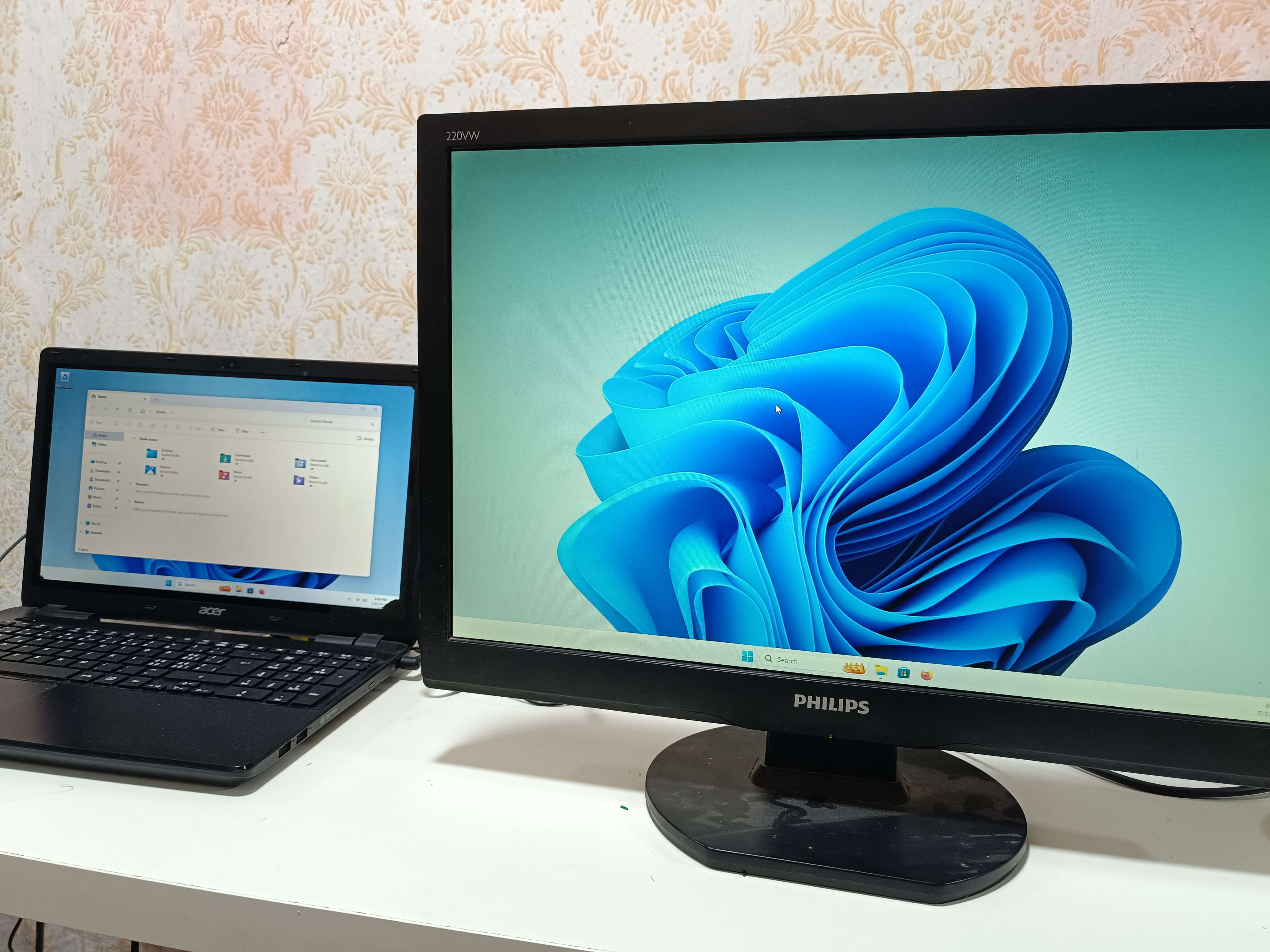
The results were truly unexpected. We didn’t anticipate such a significant improvement in image quality — the colors became much more vibrant. There are no dark areas, and the light is evenly distributed across the screen. Efficiency increased, and power consumption was reduced by 30%.
The plan is to create an open-source, universal modular board for displays (composed of multiple parts/modules). This board currently combines several modules. For now, this is sufficient for us to recycle and upgrade monitors that arrive for recycling through the project Поново.
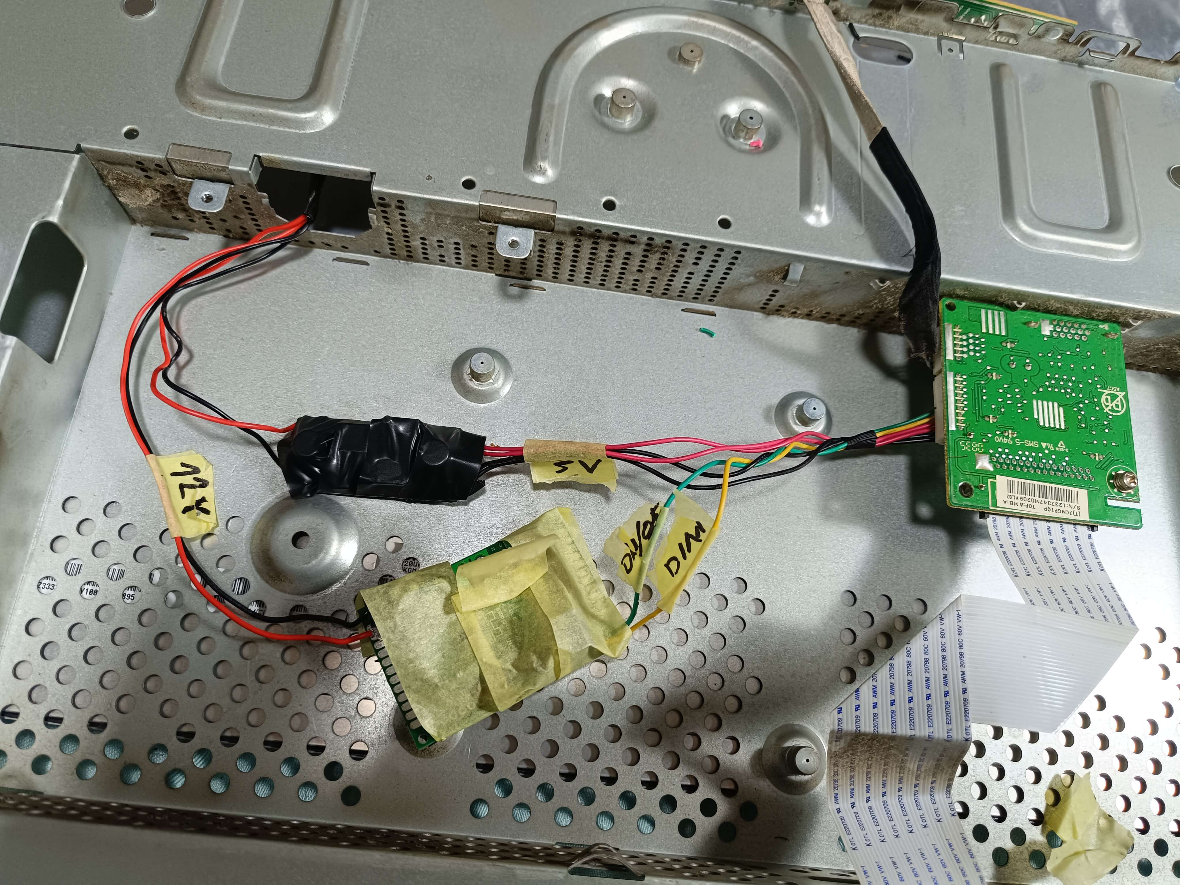
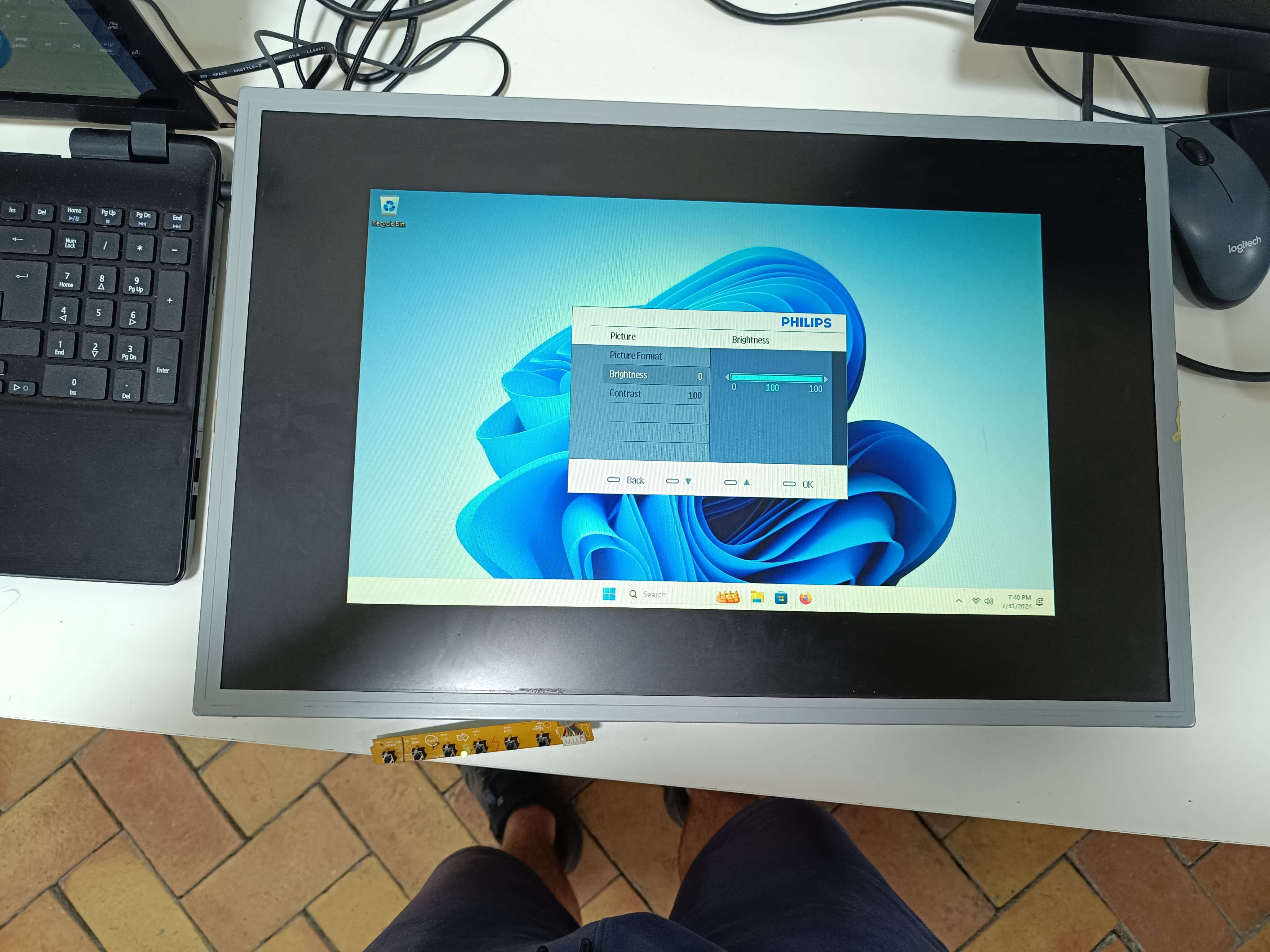
Here are picture of the working prototype (with the same chip tested on a 19", 22" and 24" display):
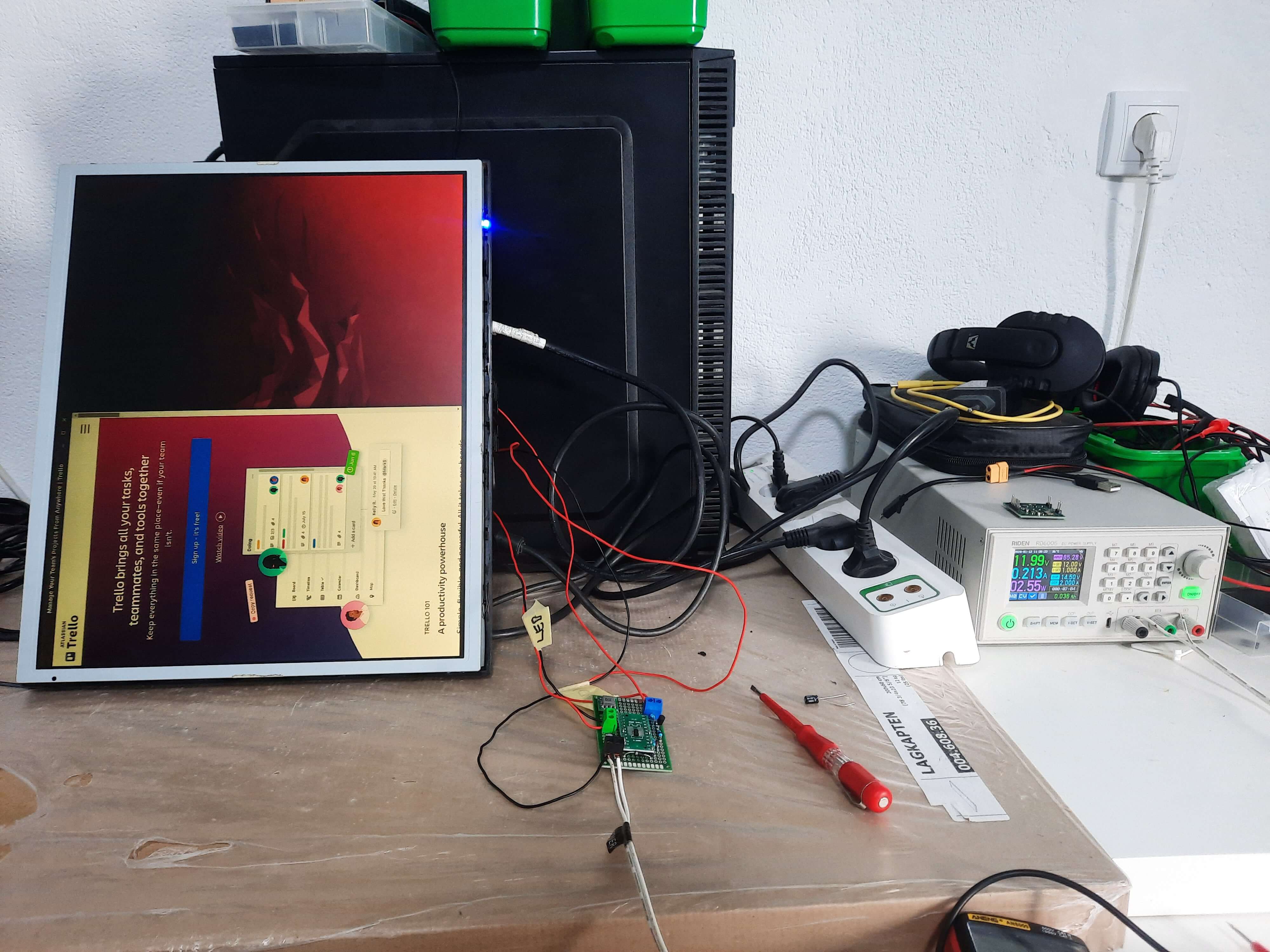
Warning: This particular board has not yet been fully tested! It has only been tested using separate modules.
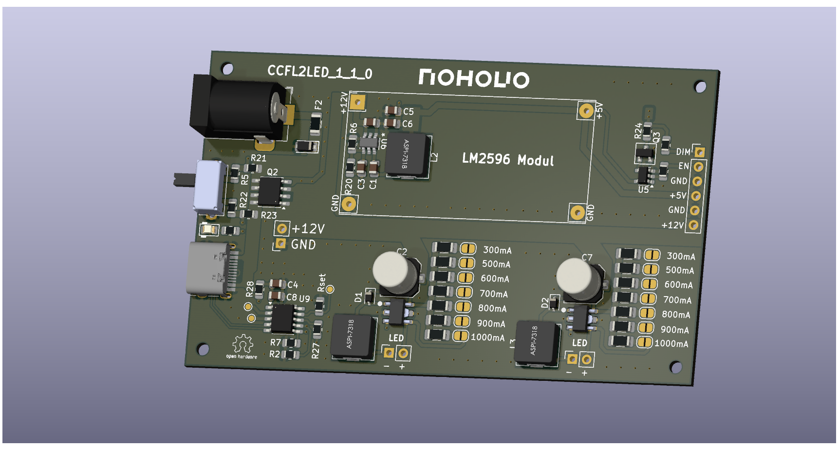
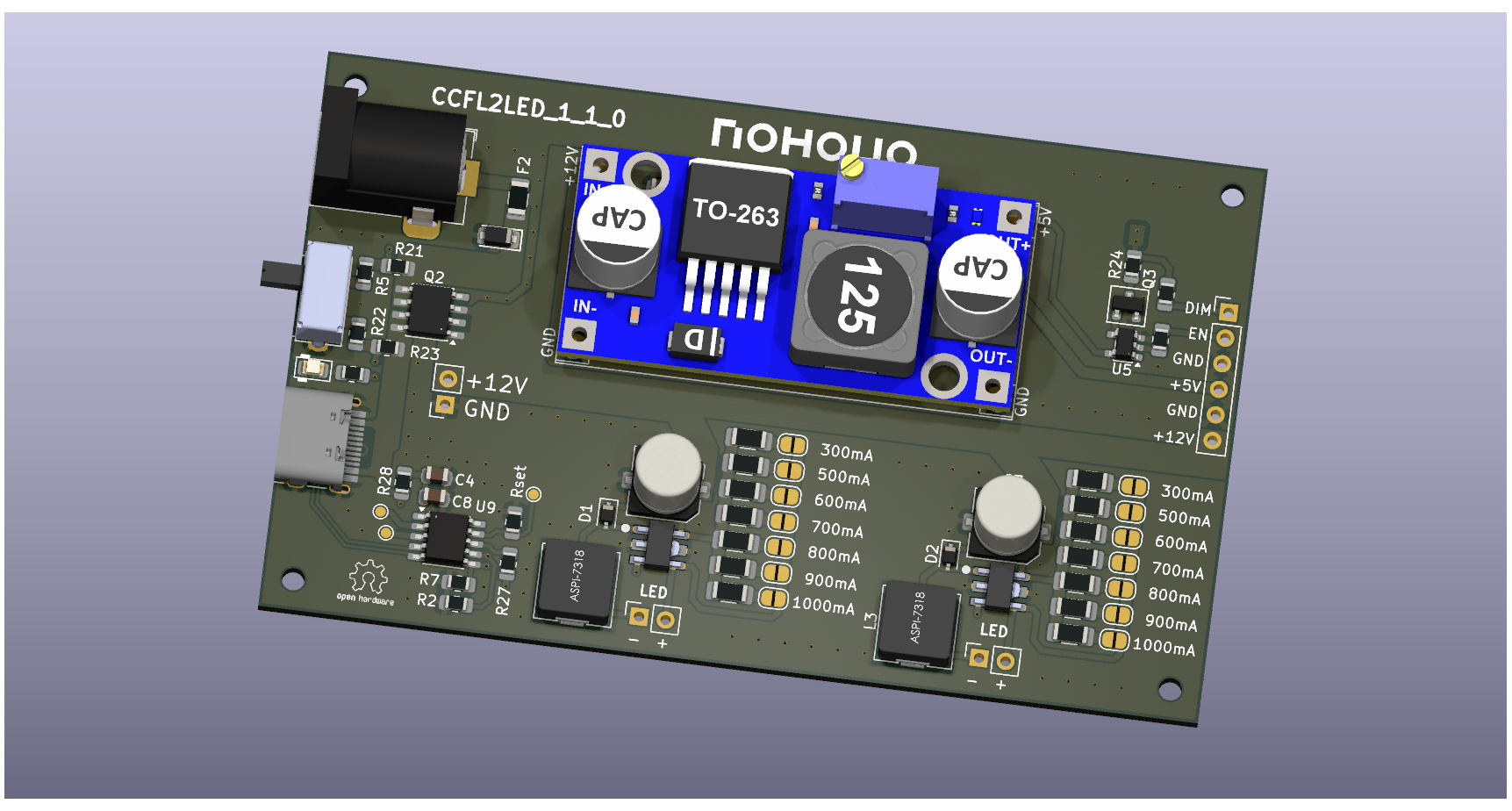
We recommend using a strip with 120 LEDs per meter. It’s also possible to implement the mod with a 60 LEDs/m strip, but the brightness will be noticeably lower. LED's must be 6500k color. Testing of different sizes of LED strip is in progress...
A maximum of 36W is required (typically around 30W depending on screen size and number of LEDs). There are two input options, selectable via a switch. The USB-C Power Delivery input uses the CH224K chip configured for a 12V output, so it's crucial to ensure that your adapter supports 12V PD — otherwise, it will not work. The second input is a standard DC jack (5.5mm outer, 2.0mm inner, center-positive) with a 12V power supply.
One PT4115 driver is used per side (especially important for larger screen sizes). Below is a table showing LED strip power consumption. 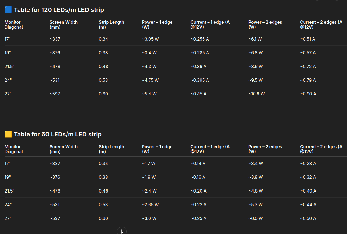 Also included is a table with required resistor values.
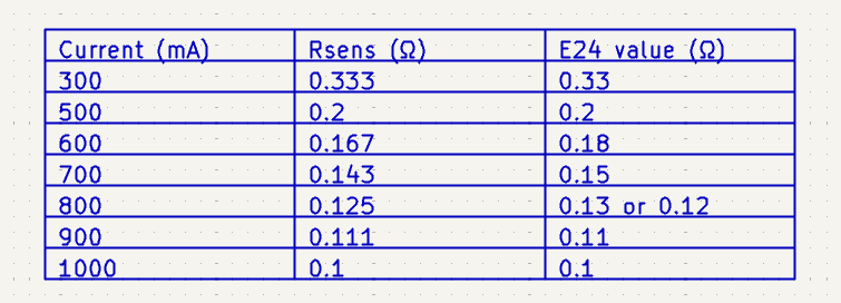
There are two options for the buck converter:
Warning: Before starting, make sure to clean the workspace and put on gloves!!!
The steps we will go through in this process are:
Carefully open the display and separate the backlight and the panel from the electronic boards.
-Be careful with the LVDS cable going to the panel
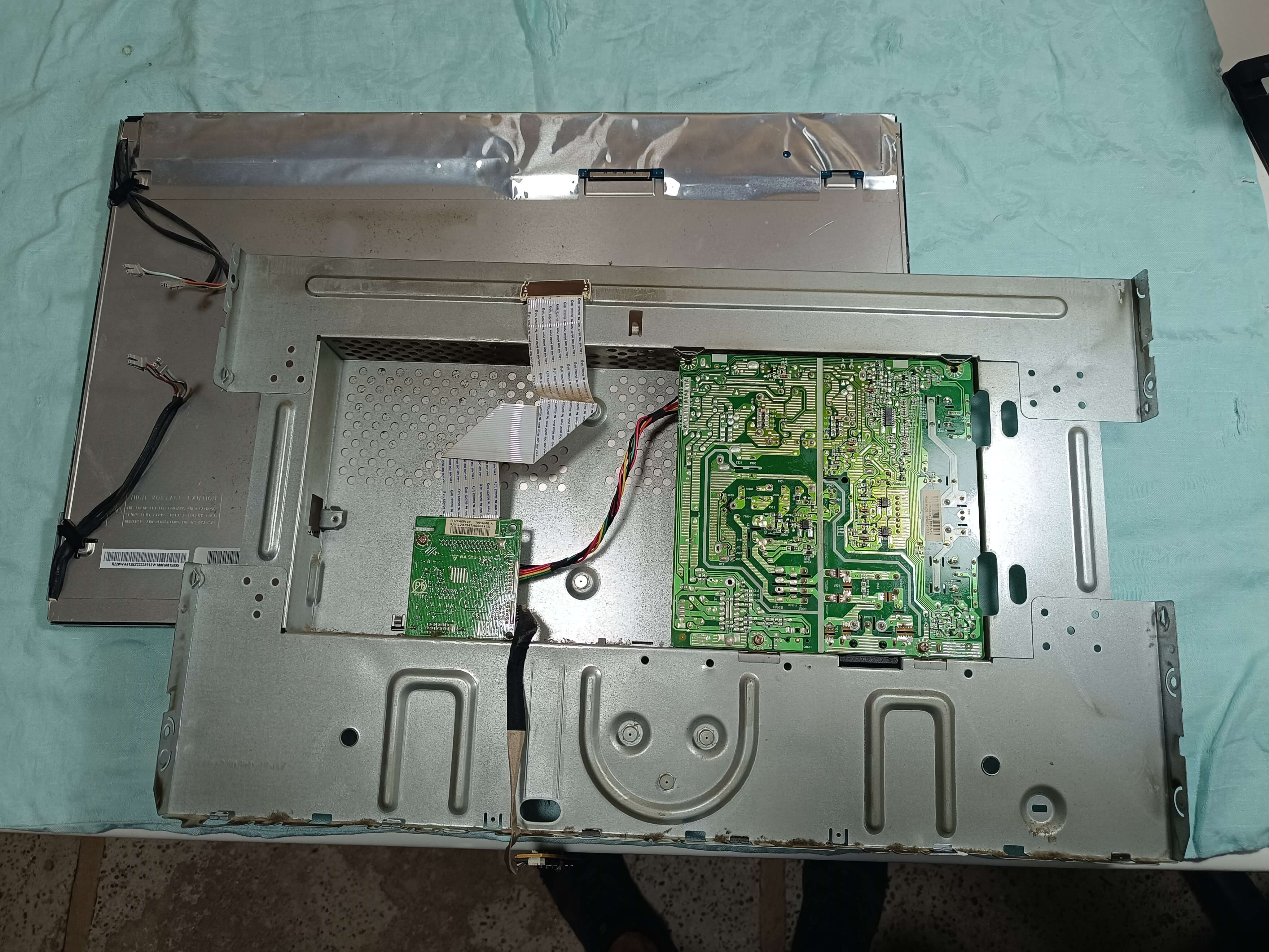
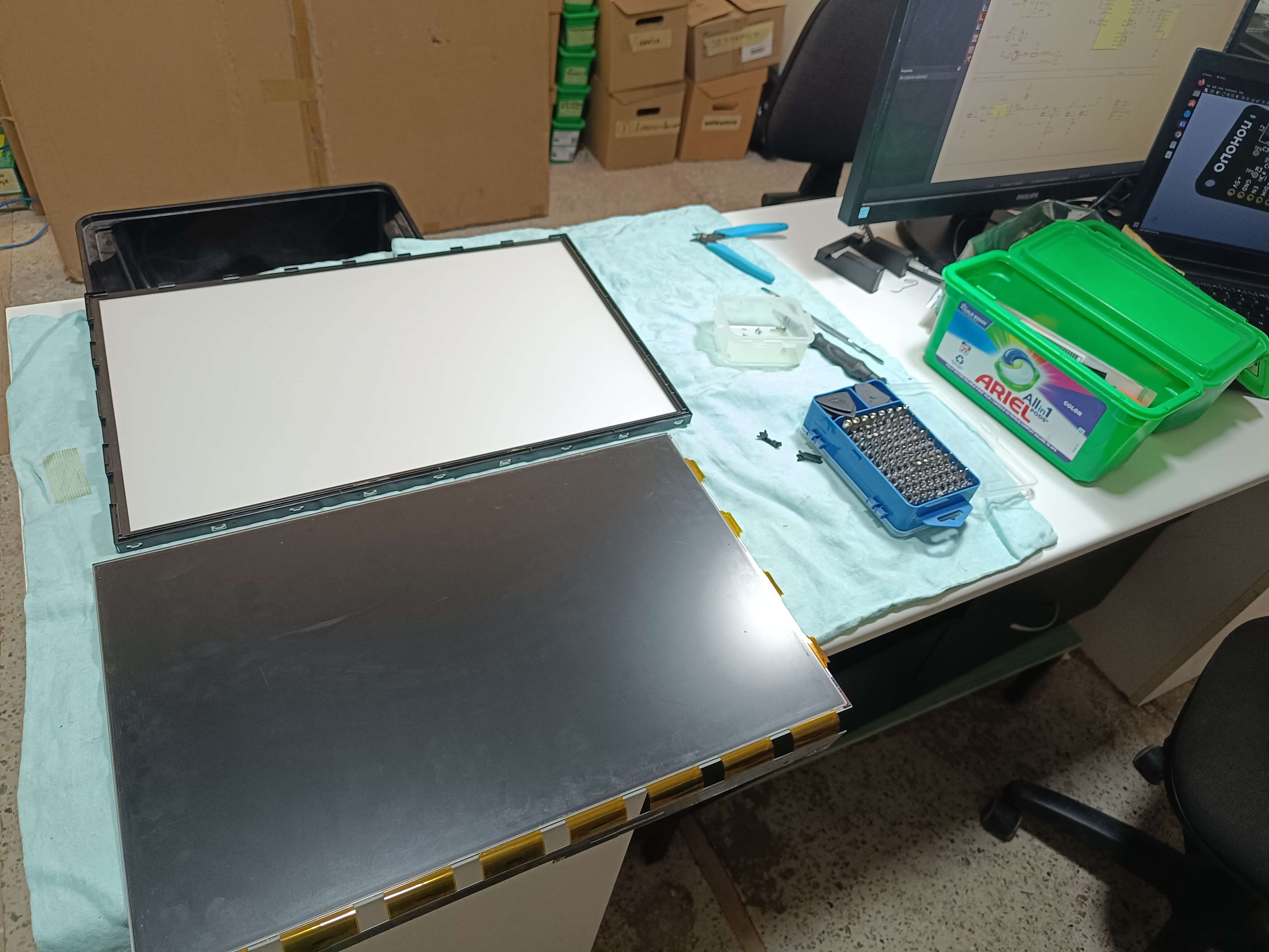
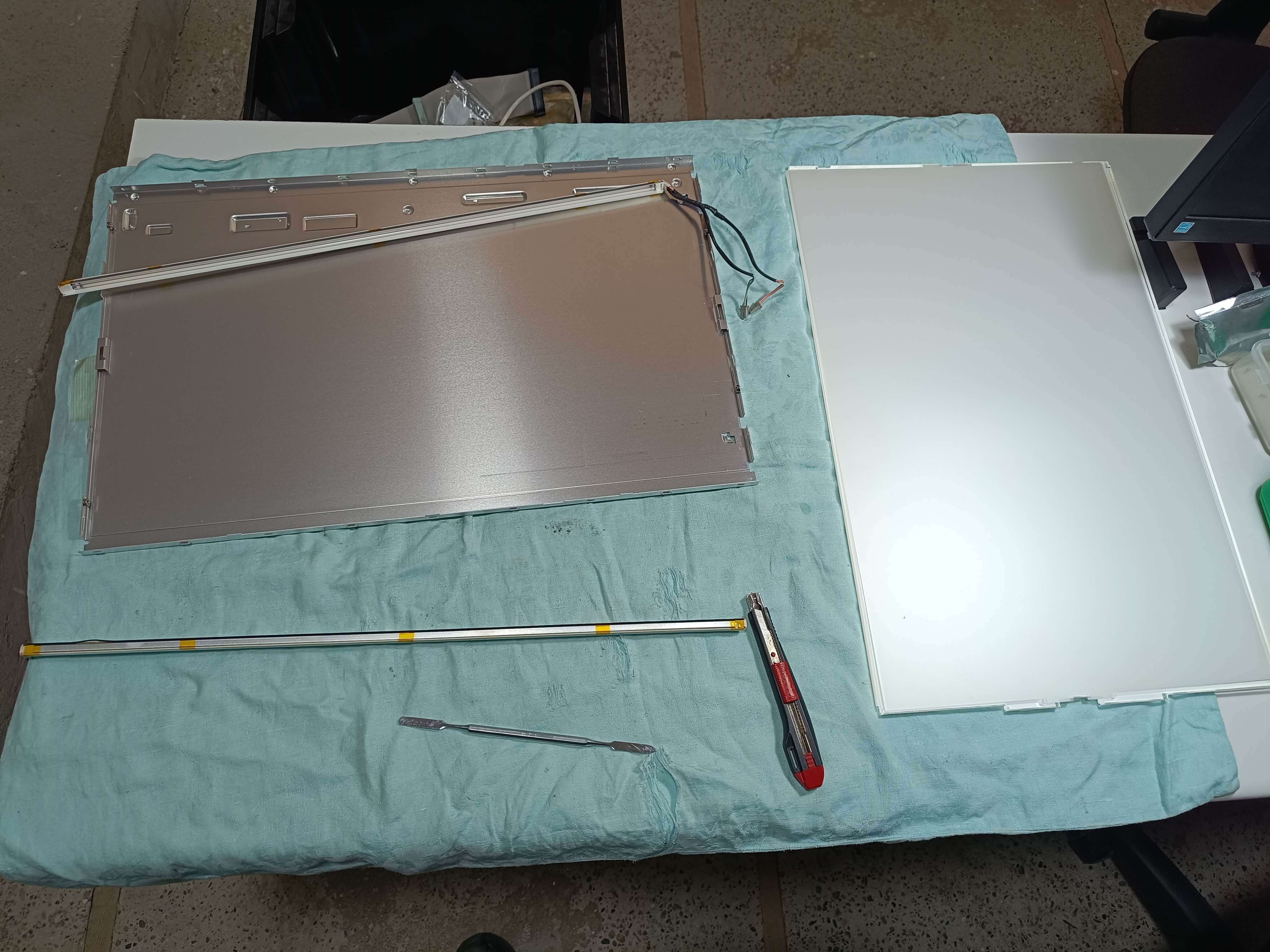
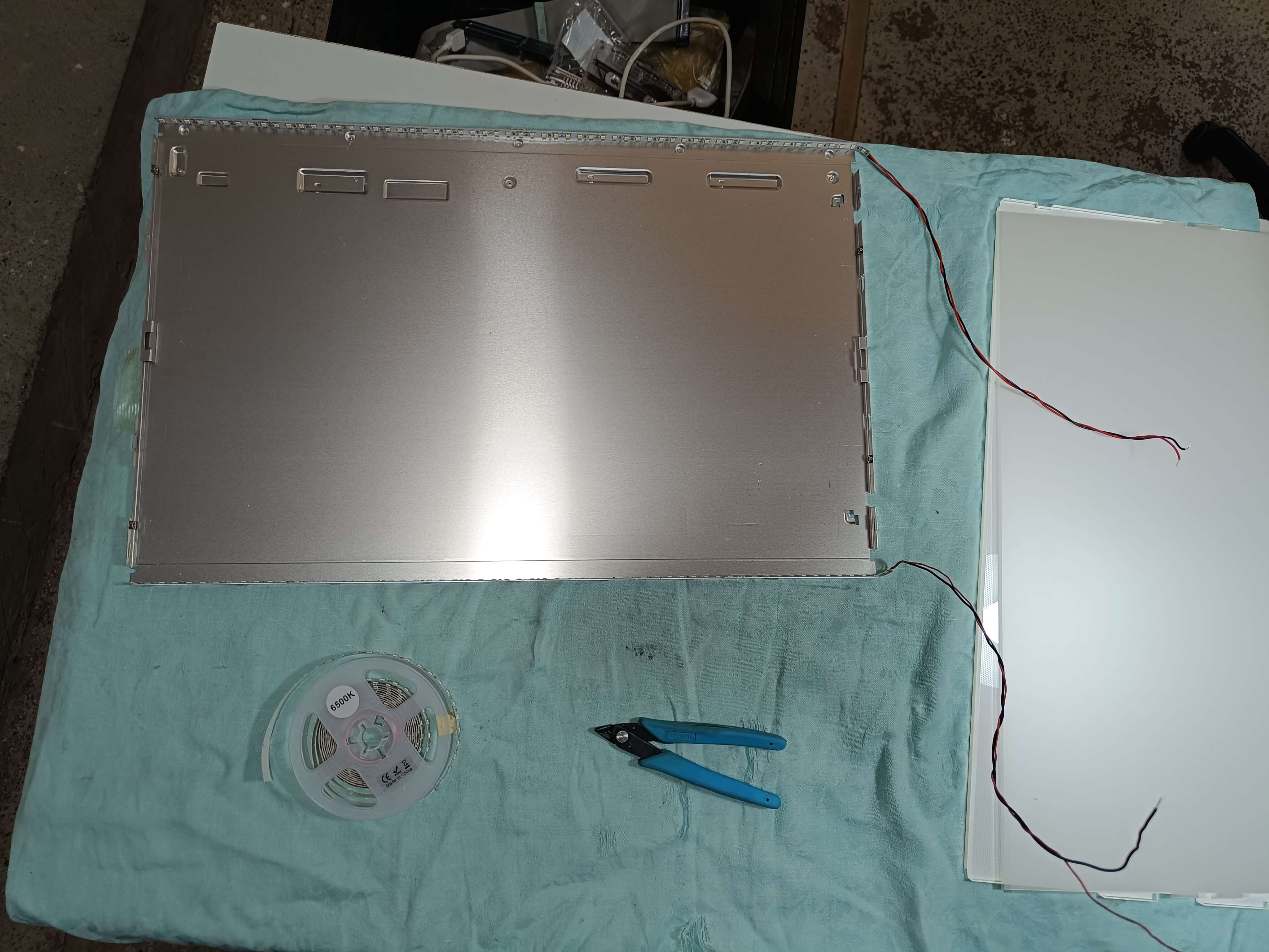
-An example of bad backlighting
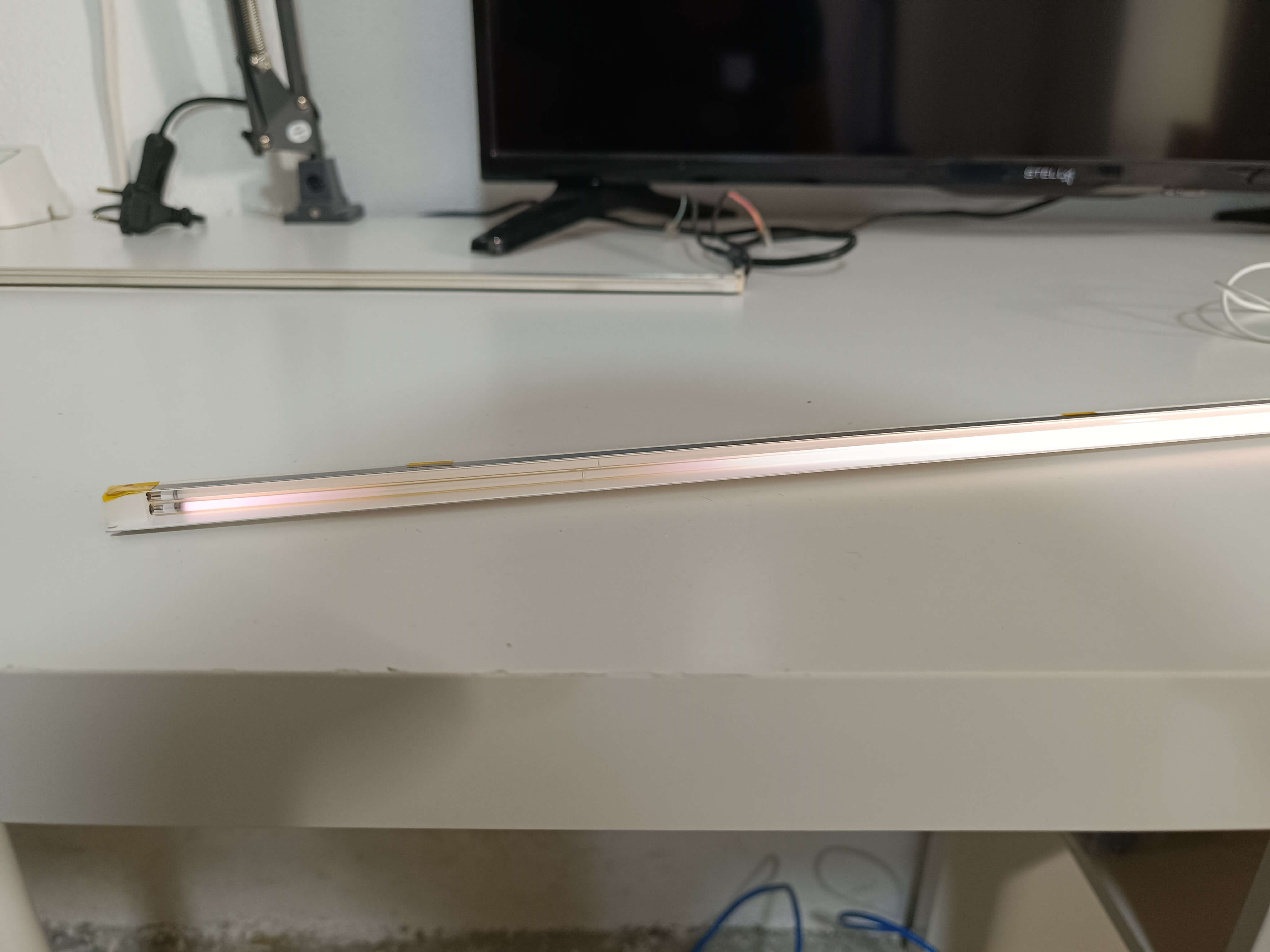
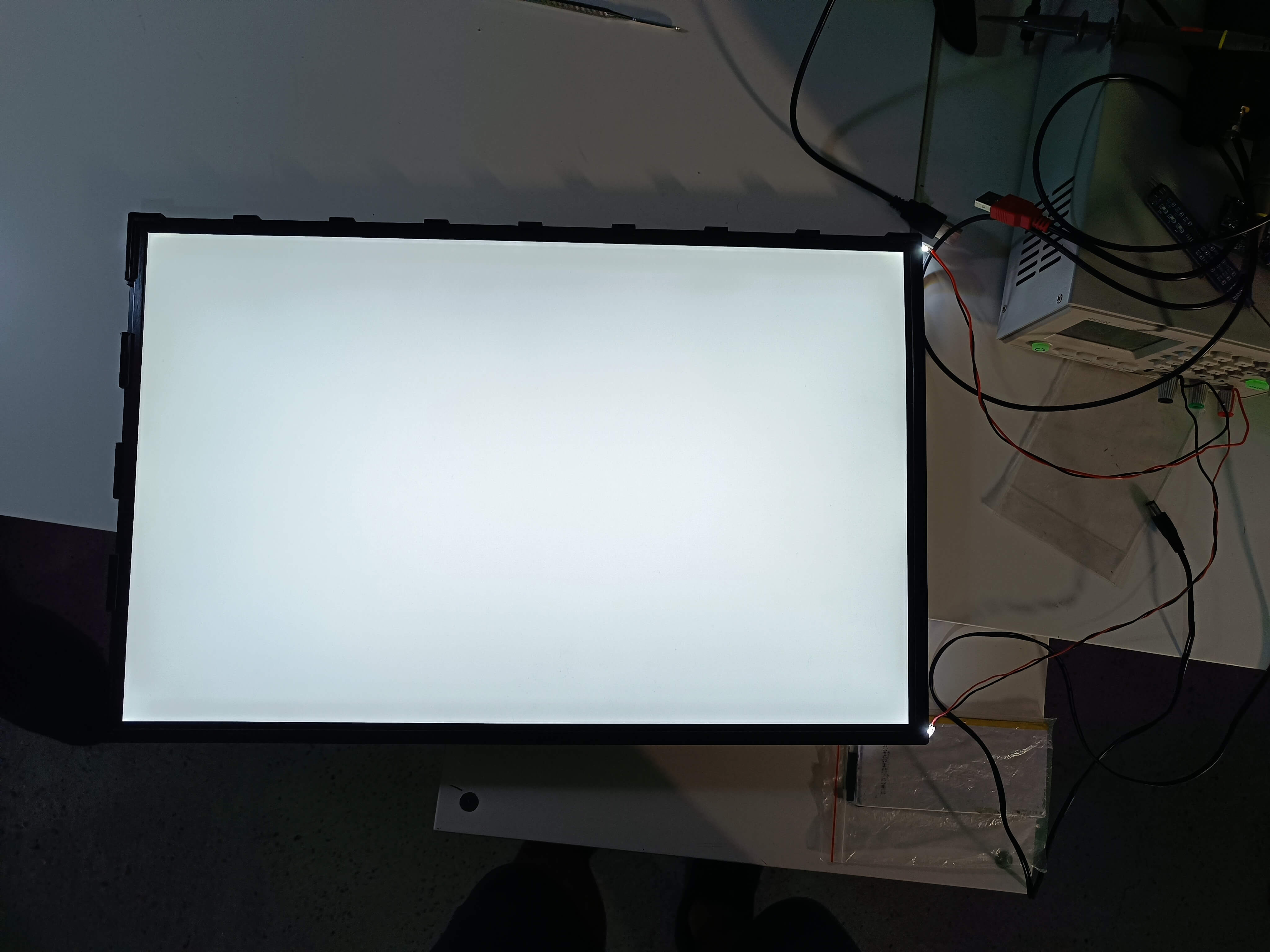
-Badly returned diffusers will have lines on the edges which is the case here
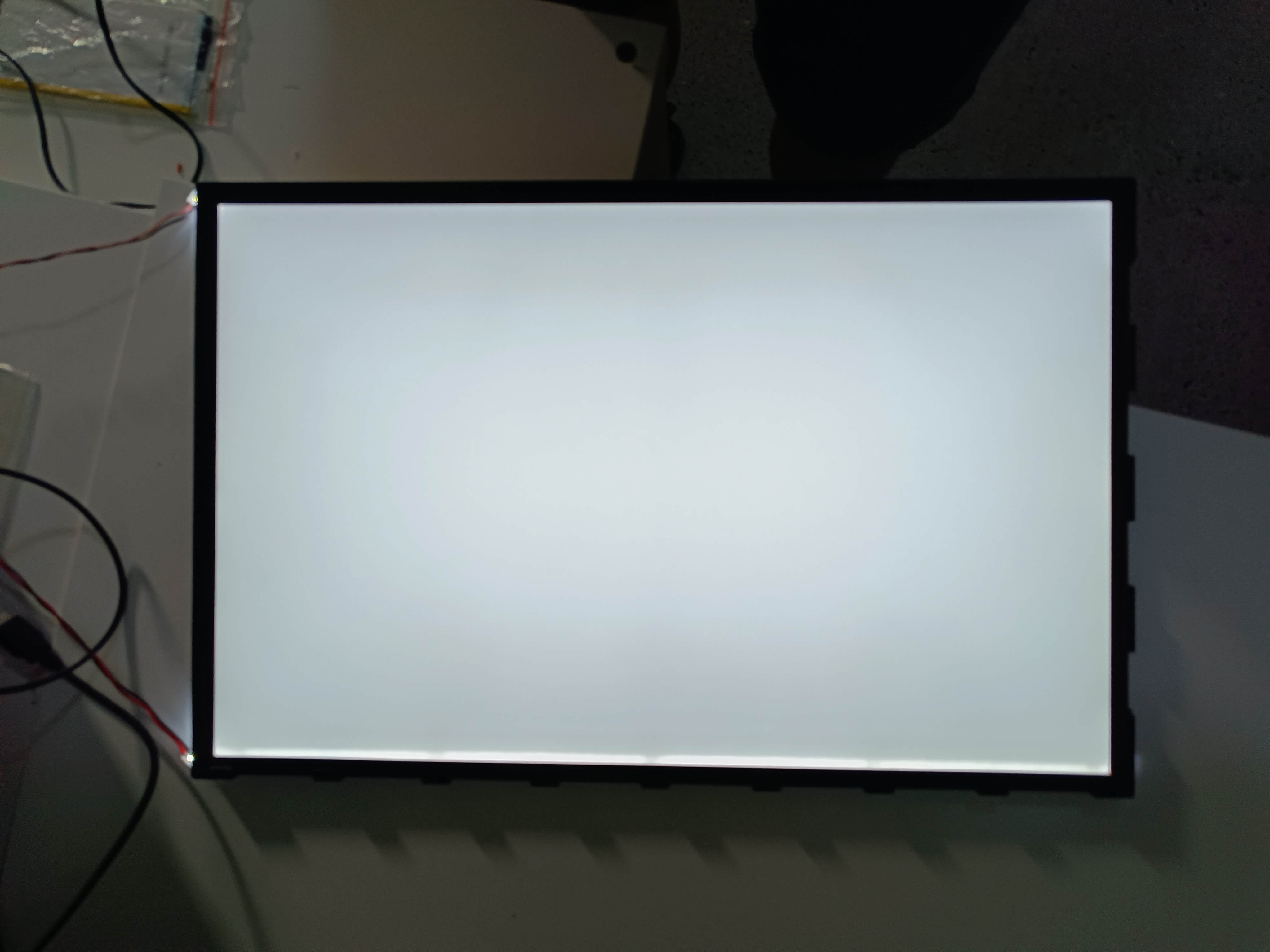
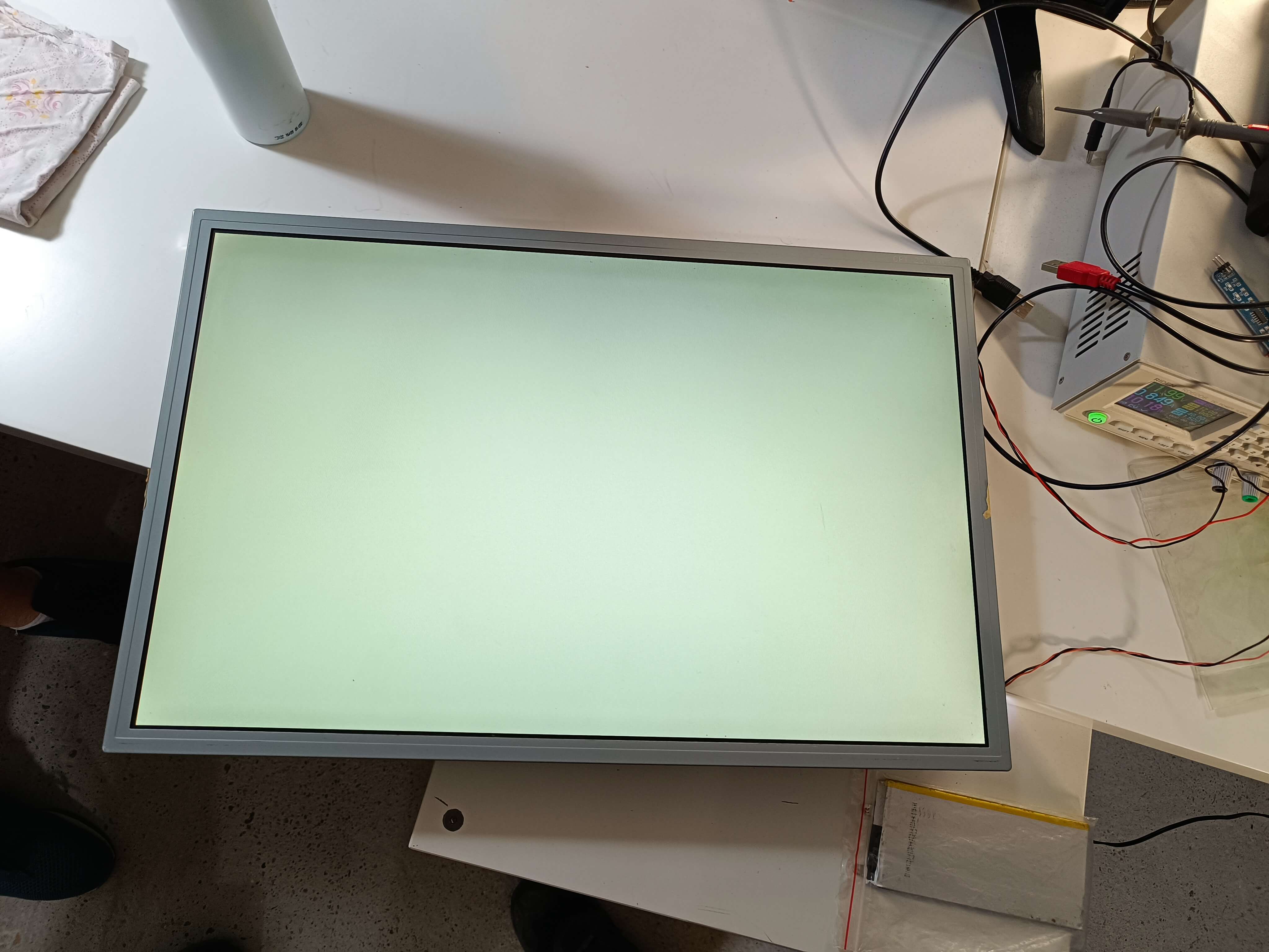
-In this picture, the LED strips are not connected (I don't have a picture when they are connected)
| Qty | Value | Footprint | References |
|---|---|---|---|
| 14 | SolderJumper_2_Open | Jumper:SolderJumper-2_P1.3mm_Open_RoundedPad1.0x1.5mm | JP1, JP2, JP3, JP4, JP5, JP6, JP7, JP8, JP9, JP10, JP11, JP12, JP13, JP14 |
| 5 | 1K | Resistor_SMD:R_0805_2012Metric_Pad1.20x1.40mm_HandSolder | R1, R5, R22, R25, R28 |
| 4 | MountingHole | MountingHole:MountingHole_2.2mm_M2 | H1, H2, H3, H4 |
| 2 | 0.11R | Resistor_SMD:R_1206_3216Metric_Pad1.30x1.75mm_HandSolder | R11, R18 |
| 2 | 0.13R | Resistor_SMD:R_1206_3216Metric_Pad1.30x1.75mm_HandSolder | R10, R17 |
| 2 | 0.15R | Resistor_SMD:R_1206_3216Metric_Pad1.30x1.75mm_HandSolder | R9, R16 |
| 2 | 0.18R | Resistor_SMD:R_1206_3216Metric_Pad1.30x1.75mm_HandSolder | R8, R15 |
| 2 | 0.1R | Resistor_SMD:R_1206_3216Metric_Pad1.30x1.75mm_HandSolder | R12, R19 |
| 2 | 0.2R | Resistor_SMD:R_1206_3216Metric_Pad1.30x1.75mm_HandSolder | R4, R14 |
| 2 | 0.33R | Resistor_SMD:R_1206_3216Metric_Pad1.30x1.75mm_HandSolder | R3, R13 |
| 2 | 100K | Resistor_SMD:R_0805_2012Metric_Pad1.20x1.40mm_HandSolder | R21, R23 |
| 2 | 100nF | PCM_JLCPCB:C_0805 | C1, C4 |
| 2 | 100uF | Capacitor_SMD:C_Elec_6.3x7.7 | C2, C7 |
| 2 | 10K | Resistor_SMD:R_0805_2012Metric_Pad1.20x1.40mm_HandSolder | R6, R27 |
| 2 | 1N5819WS | Diode_SMD:D_SOD-323 | D1, D2 |
| 2 | 22uF | PCM_JLCPCB:C_0805 | C5, C6 |
| 2 | 33uH | Inductor_SMD:L_7.3x7.3_H4.5 | L1, L3 |
| 2 | 5K1 | Resistor_SMD:R_0805_2012Metric_Pad1.20x1.40mm_HandSolder | R2, R7 |
| 2 | CFG2 | TestPoint:TestPoint_Pad_D1.0mm | CFG1, CFG2 |
| 2 | Conn_01x02_Pin | Connector_PinSocket_2.54mm:PinSocket_1x02_P2.54mm_Vertical | + -, + - |
| 2 | PT4115 | LED_Driver_Global:SOT-89-5 | U1, U2 |
| 1 | 0R | Resistor_SMD:R_0805_2012Metric_Pad1.20x1.40mm_HandSolder | R26 |
| 1 | 100pF | PCM_JLCPCB:C_0805 | C3 |
| 1 | 10uF | PCM_JLCPCB:C_0805 | C11 |
| 1 | 1uF | PCM_JLCPCB:C_0805 | C8 |
| 1 | 24K | Resistor_SMD:R_0805_2012Metric_Pad1.20x1.40mm_HandSolder | Rset |
| 1 | 2N7002 | PCM_Package_TO_SOT_SMD_AKL:SOT-23 | Q3 |
| 1 | 4u7H | Inductor_SMD:L_7.3x7.3_H4.5 | L2 |
| 1 | 52K3 | Resistor_SMD:R_0805_2012Metric_Pad1.20x1.40mm_HandSolder | R20 |
| 1 | AP62201WU-7 | Buck_Converters:TSOT26-WU_DIO | U6 |
| 1 | APM4953 | Package_SO:SOP-8_3.76x4.96mm_P1.27mm | Q2 |
| 1 | CFG3 | TestPoint:TestPoint_Pad_D1.0mm | CFG3 |
| 1 | CFS12V6T2R0 | Fuse:Fuse_1206_3216Metric | F2 |
| 1 | CH224K | Package_SO:SSOP-10-1EP_3.9x4.9mm_P1mm_EP2.1x3.3mm | U9 |
| 1 | External supply | Connector_PinSocket_2.54mm:PinSocket_1x02_P2.54mm_Vertical | J1 |
| 1 | Jack-DC | Connector_BarrelJack:BarrelJack_Horizontal | J3 |
| 1 | LED_0805 | PCM_LED_SMD_AKL:LED_0805_2012Metric | LED1 |
| 1 | LM2596 Modul | Buck_Converters_Global:YAAJ_DCDC_StepDown_LM2596 | U7 |
| 1 | OUTPUT | Connector_PinHeader_2.54mm:PinHeader_1x06_P2.54mm_Vertical | J4 |
| 1 | SD12CT1G | PCM_JLCPCB:D_SOD-123FL | D3 |
| 1 | SK12D07VG4 | Switch:SK12D07VG4_SPDT | U4 |
| 1 | SN74LVC1G14DBV | Package_TO_SOT_SMD:SOT-23-5 | U5 |
| 1 | USB_C_Receptacle_USB2.0_16P | Connector_USB:USB_C_Receptacle_Palconn_UTC16-G | J2 |
| 1 | ~10R | Resistor_SMD:R_0805_2012Metric_Pad1.20x1.40mm_HandSolder | R24 |
It measures 55 × 90 mm and has 2 copper layers, 1.6 mm thick.
82 parts, built around the PT4115, AP62201WU-7, CH224K and SK12D07VG4. The full list of its parts is on this page, with links to each part's symbol and footprint where PCBKit's library has them.
From the mijuc/CCFL2LED repository on GitHub, at the commit this page was made from: the board is CCFL2LED.kicad_pcb and its schematic CCFL2LED.kicad_sch. PCBKit opens the board in the browser, with nothing to install.
Its repository publishes it under the GPL-3.0 licence: you may reuse it on that licence's terms (keep the author's notice, and for a copyleft licence share your changes alike).


lisasnt/HSD-RP2040-5-stepper-motor-driver
Custom PCB with RP2040 and Stepper Drivers


LtBrain/MuBook
A x86 carrier board for the LattePanda Mu

El-Luhb/nvme-Carrier-for-LattePanda-Mu
nvme Carrier PCB for the LattePanda Mu compute module