4 layers

 yvoronkin/FailDeadly3
Fail Secure. Fail Deadly.
FailDeadly is an open-source printed circuit board by yvoronkin, from the yvoronkin/FailDeadly repository on GitHub. It is a 4-layer board of 70 × 25 mm with 101 parts on 73 nets, routed with 422 tracks and 275 vias.
It is built around the SN74LVC1G17DBVRE4, SN74LVC1G14DBV and AP2112K-3.3, with the LTV-817S, MT9700 and SN74LVC2G02DCUR among its other parts. Its parts include 42 capacitors, 30 resistors, 10 ICs, 4 connectors and 3 transistors. It belongs with the computers and single-board computers boards and the STM32 boards of this library.



Fail secure. Fail deadly.
A tamper-responsive USB root-of-trust prototype for servers without a suitable hardware trust anchor.



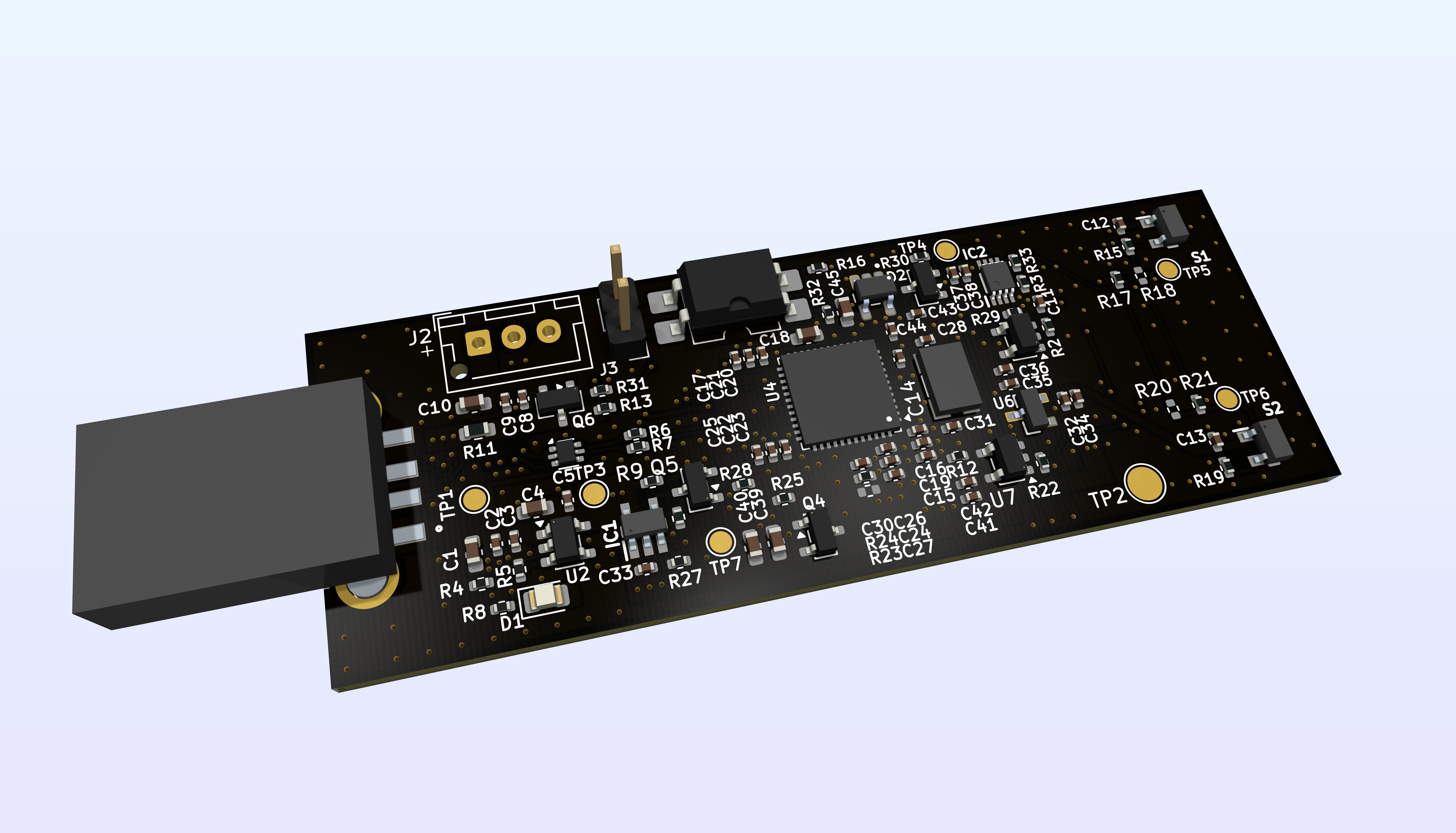
FailDeadly is an open hardware security device designed to make selected server secrets physically ephemeral. It keeps key material in MCU SRAM and monitors the server enclosure with Hall-effect sensors. When the expected magnetic field changes, a hardware-controlled path first provides the device with a short window to signal the host, then removes power from the MCU. Once SRAM loses power, the secret is gone.
The project began as a practical response to older servers where TPM 2.0 was unavailable. It is not intended to emulate every TPM feature. Instead, it explores a narrower security property: tying access to a secret to the machine's continued physical integrity.
[!WARNING] FailDeadly deliberately values confidentiality over availability. Tampering, sensor failure, power-system failure, or a false positive may permanently destroy volatile key material. The project is experimental, has not been independently audited, and must not be treated as production-ready security hardware, yet.
The central design rule is that firmware must not be able to cancel the final tamper response.
flowchart TD
	A["Lid moves relative to magnets"] --> B["Dual Hall sensors change state"]
	B --> C["Discrete logic latches the tamper event"]
	C --> D["Short host notification / reset window"]
	C --> E["MCU power is physically disconnected"]
	E --> F["Volatile secret state disappears"]
The supercapacitor is there to preserve SRAM during ordinary power loss. It does not defeat the tamper path: the power-isolation circuit disconnects the MCU from both USB power and stored energy after the response delay.
The current board is a four-layer USB device built around an STM32F401CCU6. The design includes:
The complete KiCad sources, fabrication outputs, schematic PDF, and interactive BOM are committed to this repository.
| Resource | Description |
|---|---|
| Schematic and PCB | Editable KiCad project and component libraries |
| Fabrication outputs | Gerbers and drill data for revision 001 |
| Schematic PDF | Three-page rendered schematic |
| Interactive BOM | Browser-based board inspection |
| Front / back renders | Board overview |
The firmware is intentionally structured as a security boundary rather than a single privileged application:
The crypto command API is present, but key generation/import and sign/verify/encrypt/decrtypt handlers are still under development. This distinction matters: the repository currently demonstrates the isolation and communication architecture, not a finished cryptographic product.
.
├── hardware/        KiCad sources, local libraries, and fabrication files
├── firmware/        STM32F401 firmware and PlatformIO configuration
├── docs/            Rendered schematic and interactive BOM
└── staff/ Project logo, board renders, and source artwork Requirments:
Clone the repository with its cryptographic submodule, then build:
git clone --recurse-submodules https://github.com/yvoronkin/FailDeadly.git
cd FailDeadly/firmware
pio run
Upload through ST-Link and open the serial monitor:
pio run --target upload
pio device monitor
The default PlatformIO environment uses the custom MPU-aware linker script at firmware/linker/STM32F401CCUx_MPU.ld.
| Area | Status | Notes |
|---|---|---|
| Hardware revision 001 | Design complete | Four-layer layout is DRC-clean; KiCad sources and manufacturing outputs are available |
| Board validation | Not yet documented | Electrical and destructive tamper-response test still in verification stage |
| Firmware platform | In progress | USB, RTOS/MPU task isolation, logging, parser and hardware CRC foundation exist |
| Cryptographic operations | In progress | Minimal crypto profile and volatile storage exist; command handlers remain incomplete |
| Host tooling | Planned | Provisioning, lifecycle management, and recovery tooling |
| Vault / attestation integration | Planned | Challenge-response login and infrastructure policy integration |
Near-term work is tracked in the repository history and will focus on hardware bring-up, repeatable tamper timing measurements, completion of the crypto service, host tooling, and tests around trust-boundaty failures.
FailDeadly is intentionally opinionated:
These choices do not make the system unbreakable. They make its assumptions, failure mode, and trust boundaries concrete enough to analyze and test.
This repository contains multiple independently licensed components:
See the license file within each component directory before reuse or redistribution.
| Qty | Value | Footprint | References |
|---|---|---|---|
| 15 | 100nf | Capacitor_SMD:C_0402_1005Metric | C3, C5, C8, C12, C13, C19, C21, C22, C24, C30, C32, C36, C38, C42, C44 |
| 9 | 100k | Resistor_SMD:R_0402_1005Metric | R3, R5, R9, R10, R12, R15, R19, R22, R29 |
| 9 | 10nf | Capacitor_SMD:C_0402_1005Metric | C2, C14, C16, C20, C23, C26, C33, C34, C41 |
| 9 | 1uf | Capacitor_SMD:C_0402_1005Metric | C9, C11, C15, C17, C25, C27, C35, C37, C43 |
| 6 | 0 | Resistor_SMD:R_0402_1005Metric | R17, R18, R20, R21, R23, R33 |
| 5 | 10uf | Capacitor_SMD:C_0603_1608Metric | C1, C4, C10, C39, C40 |
| 3 | 10k | Resistor_SMD:R_0402_1005Metric | R2, R4, R24 |
| 3 | 470k | Resistor_SMD:R_0402_1005Metric | R25, R28, R31 |
| 3 | IRLML6401 | Package_TO_SOT_SMD:SOT-23 | Q4, Q5, Q6 |
| 2 | 18pf | Capacitor_SMD:C_0402_1005Metric | C28, C31 |
| 2 | 1M | Resistor_SMD:R_0402_1005Metric | R13, R30 |
| 2 | 22 | Resistor_SMD:R_0402_1005Metric | R6, R7 |
| 2 | 220 | Resistor_SMD:R_0402_1005Metric | R8, R16 |
| 2 | AH180-WG-7 | Library:AH180WG7 | S1, S2 |
| 2 | SN74LVC1G14DBV | Package_TO_SOT_SMD:SOT-23-5 | U5, U7 |
| 1 | 1k | Resistor_SMD:R_0402_1005Metric | R32 |
| 1 | 2.2uF | Capacitor_SMD:C_0603_1608Metric | C18 |
| 1 | 4.7uF | Capacitor_SMD:C_0603_1608Metric | C45 |
| 1 | 47 | Resistor_SMD:R_0603_1608Metric | R11 |
| 1 | 6.2k | Resistor_SMD:R_0402_1005Metric | R27 |
| 1 | AP2112K-3.3 | Package_TO_SOT_SMD:SOT-23-5 | U2 |
| 1 | BAT54A | Package_TO_SOT_SMD:SOT-23 | D2 |
| 1 | Conn_02x04_Odd_Even | Connector_PinHeader_2.54mm:PinHeader_2x04_P2.54mm_Vertical_SMD | J4 |
| 1 | EXTERNAL_RESET | Connector_PinHeader_2.54mm:PinHeader_1x02_P2.54mm_Vertical | J3 |
| 1 | GND | TestPoint:TestPoint_Pad_D2.5mm | TP2 |
| 1 | HALL1 | TestPoint:TestPoint_Pad_D1.5mm | TP5 |
| 1 | HALL2 | TestPoint:TestPoint_Pad_D1.5mm | TP6 |
| 1 | KLS1-180B-W | Library:KLS1180BW | J1 |
| 1 | KX-9A 25Mhz | Library:KX9A | Y1 |
| 1 | LED_RED | LED_SMD:LED_0805_2012Metric | D1 |
| 1 | LTV-817S | Package_DIP:SMDIP-4_W9.53mm | U3 |
| 1 | MCP121T-270E_TT | Library:SOT95P237X112-3N | U6 |
| 1 | MT9700 | Library:SOT95P280X135-5N | IC1 |
| 1 | PWR_DOWN | TestPoint:TestPoint_Pad_D1.5mm | TP7 |
| 1 | RST_LATCH_OUT | TestPoint:TestPoint_Pad_D1.5mm | TP4 |
| 1 | SN74LVC1G17DBVRE4 | Library:SOT95P280X145-5N | U8 |
| 1 | SN74LVC2G02DCUR | Library:SOP50P310X90-8N | IC2 |
| 1 | STM32F401CCUx | Package_DFN_QFN:QFN-48-1EP_7x7mm_P0.5mm_EP5.6x5.6mm | U4 |
| 1 | USBLC6-2P6 | Package_TO_SOT_SMD:SOT-666 | U1 |
| 1 | USB_SENSE | TestPoint:TestPoint_Pad_D1.5mm | TP3 |
| 1 | VBUS | TestPoint:TestPoint_Pad_D1.5mm | TP1 |
| 1 | ionister_conn | Connector_JST:JST_XH_B3B-XH-AM_1x03_P2.50mm_Vertical | J2 |
It measures 70 × 25 mm and has 4 copper layers, 1.57 mm thick.
101 parts, built around the SN74LVC1G17DBVRE4, SN74LVC1G14DBV, AP2112K-3.3 and LTV-817S. The full list of its parts is on this page, with links to each part's symbol and footprint where PCBKit's library has them.
From the yvoronkin/FailDeadly repository on GitHub, at the commit this page was made from: the board is hardware/FailDeadly/FailDeadly.kicad_pcb and its schematic hardware/FailDeadly/FailDeadly.kicad_sch. PCBKit opens the board in the browser, with nothing to install.
Its repository states no licence, so its author keeps all rights: ask yvoronkin before reusing the design.


pdyxs/glider
Fork of zephray/glider (Modos Glider e-ink monitor) with a DP AUX polarity fix and a standalone GCC firmware build

CameraNexus/sitina1
Open-source 35mm full-frame (36mm x 24mm) CCD mirror-less interchangable lens camera (MILC). The original goal of this project was to create a digital camera back to convert SLR cameras to DSLR cameras, but has since…


openconcepts-ar/accel2d
This project aims to provide a graphics server system based on hardware accelerated graphics, and a easy way to develop the graphics primitives.
