
2 layers320.9 × 84.4 mm

 zzeneg/stront353
Split keyboards with 38 or 40 keys, LCD display and Cirque trackpad
Mx40 is an open-source printed circuit board by zzeneg, from the zzeneg/stront repository on GitHub, published under the MIT licence. It is a 2-layer board of 321 × 92.3 mm with 181 parts on 142 nets, routed with 1,947 tracks and 173 vias.
It is built around the RP2040-ZERO. Its parts include 82 diodes, 40 switches and 4 resistors. It belongs with the keyboards and input and lEDs and displays boards and the RP2040 boards of this library.
Family of modular split keyboards with 38 or 40 keys, LCD display and Cirque/Azoteq trackpad.
All versions:
| MX-40 | MX-38 | Choc | |
|---|---|---|---|
| Number of keys | 40 | 38 | 38 |
| Supported switches | MX/KS[1] | MX/KS[1] | Choc v1 |
| Interconnect | USB-C | USB-C/TRRS | USB-C/TRRS |
| Interconnect | USB-C | USB-C/TRRS | USB-C/TRRS |
| VIK support | :heavy_check_mark: | :heavy_check_mark: | :x: |
| Module system | :heavy_check_mark: | :heavy_check_mark: | :x: |
| Splay | :x: | :x: | :heavy_check_mark: |
[1]: KS-33/KS-27 - Gateron Low Profile switches, not compatible with MX footprint and require special hotswap sockets
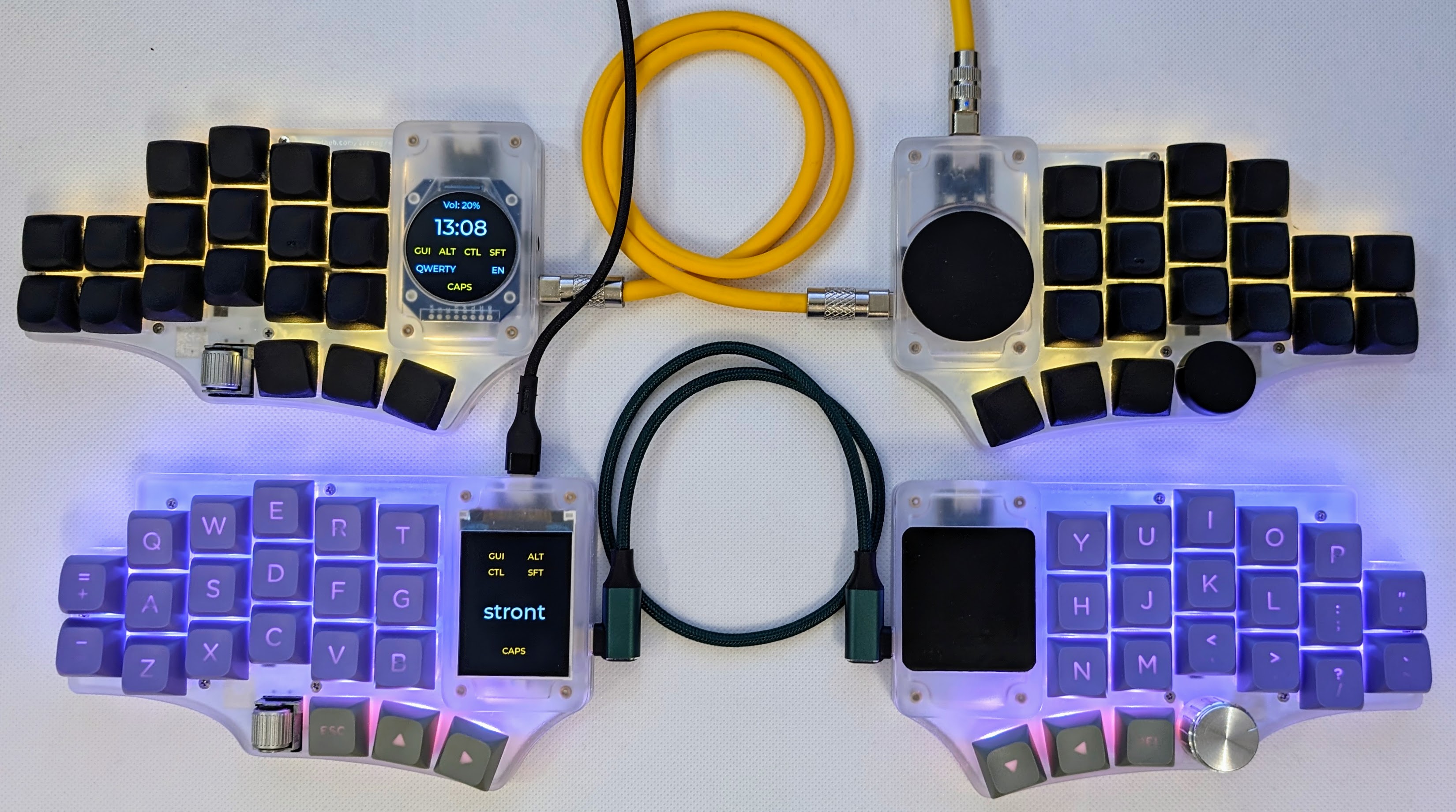
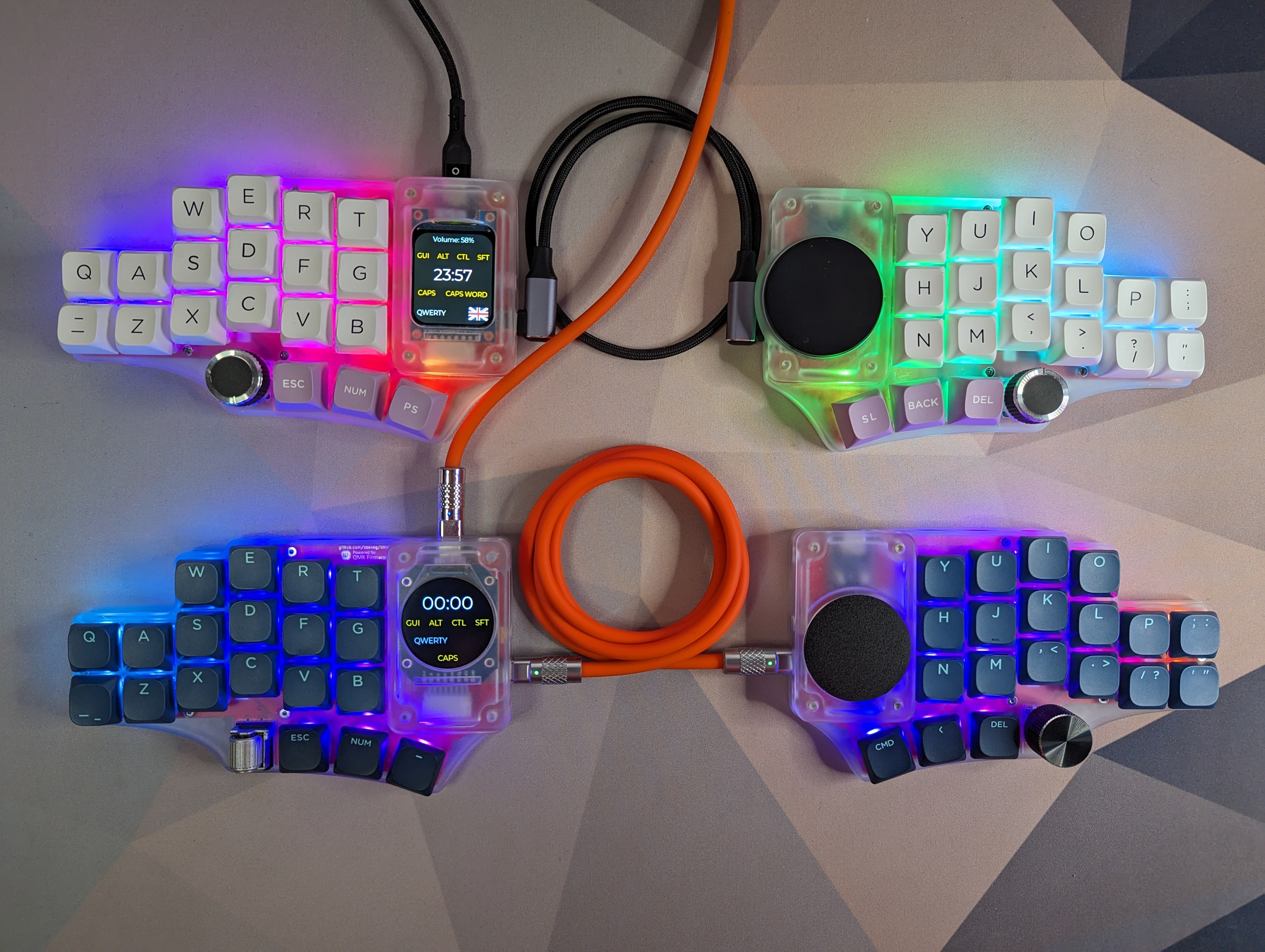
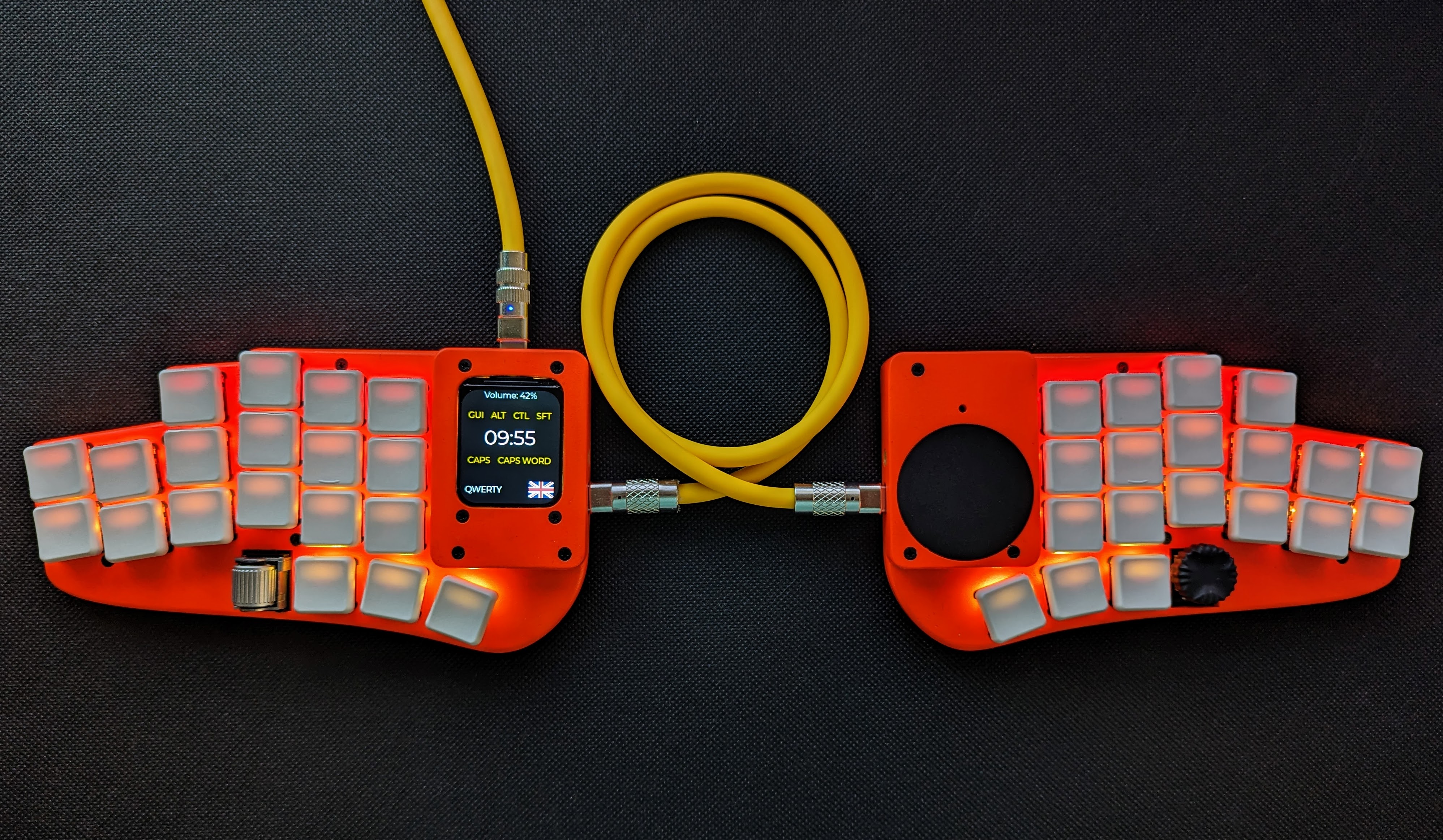
https://github.com/zzeneg/stront/assets/910255/bb812821-9b2b-454a-a9a5-45d696a1f5aa
Companion app for Raw HID communication.
Please see main config.h and rules.mk for comments and available options.
Each firmware name has two modules, first is on the left side, second on the right, e.g. if your keyboard has Azoteq on the left and round display on the right - choose
azoteq-round
default - sample keymap with home row mods. Not recommended for longer use - create your own.hid - default keymap with HID support. Requires companion application.zzeneg - my highly customized layout.-rect- - rectangular display (ST7789 240x280)-round- - round display (GC9A01 240x240)-flat- - flat 40mm Cirque-curved- - curved 40mm Cirque-azoteq- - Azoteq TPS43[!WARNING] For 38keys version with VIK display adapter - redefine LCD pins in
config.has in 40keys version
[!NOTE] VIK is a standard for a data interface between printed circuit boards. It is intended to provide modularity between a mechanical keyboard PCB and additional features.
| Category | Classification | Response |
|---|---|---|
| FPC connector | Required | :heavy_check_mark: |
| Breakout pins | Recommended | :heavy_check_mark: |
| Supplies: SPI | Strongly recommended | :heavy_check_mark: [1] |
| Supplies: I2C | Strongly recommended | :heavy_check_mark: [1] |
| I2C on main PCB | Discouraged | No |
| I2C pull ups | Informative | Optional[2] |
| Supplies: RGB | Strongly recommended | :heavy_check_mark: |
| Supplies: Extra GPIO 1 | Required | Digital |
| Supplies: Extra GPIO 2 | Required | Digital |
[1]: I2C and SPI use same pins, so you can use only one or the other, not both. Selection is configured in firmware.
[2]: PCB has pads designed for 1206/3216 SMD resistors, you can solder them manually if needed.
Built-in display and trackpad use the same interface, so any additional VIK module will have to replace one of them (it's possible to combine other I2C modules with Azoteq). Depending on the size it can integrated into the cover or a standalone case.
All possible connectors support VIK - FPC horizontal on the back, FPC vertical on the front and the breakout pins.
If you like my work and want to support my future designs, please consider sponsorship, ordering from PCBWay using my shared projects - Choc or MX38, or using referral link for signing up.
Thank you very much for your support!

| Qty | Value | Footprint | References |
|---|---|---|---|
| 42 | D | zzkeeb:Diode_1N4148-SOD123 | D1, D2, D10, D11, D12, D13, D14, D15, D16, D17, D18, D19, D20, D21, D22, D23 +26 |
| 40 | Switch | zzkeeb:Switch_MXKS-hotswap-south | SW1, SW2, SW10, SW11, SW12, SW13, SW14, SW15, SW16, SW17, SW18, SW19, SW20, SW21, SW22, SW23 +24 |
| 40 | YS-SK6812MINI-E | zzkeeb:LED_SK6812-MINI-E | LED1, LED2, LED10, LED11, LED12, LED13, LED14, LED15, LED16, LED17, LED18, LED19, LED20, LED21, LED22, LED23 +24 |
| 18 | MountingHole | zzkeeb:Hole_M2 | H1, H2, H3, H4, H5, H6, H7, H10, H11, H12, H13, H14, H15, H16, H17, H18 +2 |
| 6 | SolderJumper_2_Open | Jumper:SolderJumper-2_P1.3mm_Open_RoundedPad1.0x1.5mm | JP1, JP2, JP3, JP4, JP5, JP6 |
| 4 | MountingHole | zzkeeb:Hole_Breakaway-Tabs | BR1, BR2, BR3, BR4 |
| 4 | R | Resistor_SMD:R_1206_3216Metric | R1, R2, R3, R4 |
| 2 | Connector_HRO-TYPE-C-31-M-12 | zzkeeb:Connector_HRO-TYPE-C-31-M-12-data | USB1, USB2 |
| 2 | Connector_VIK-keyboard | zzkeeb:Connector_VIK-vertical-keyboard | VIK_K1, VIK_K4 |
| 2 | Connector_VIK-keyboard | vik:vik-keyboard-connector-horizontal | VIK_K3, VIK_K6 |
| 2 | Connector_VIK-keyboard | vik:vik-keyboard-throughole | VIK_K2, VIK_K5 |
| 2 | Display_generic-spi-8pin | zzkeeb:Connector_Display-8pin-SPI-2.0mm | DISP1, DISP2 |
| 2 | GP17 | TestPoint:TestPoint_Pad_D1.5mm | TP1, TP2 |
| 2 | RollerEncoder_EVQWGD001 | zzkeeb:RotaryEncoder_EVQWGD001 | ROLL1, ROLL2 |
| 2 | RotaryEncoder_Switch | zzkeeb:RotaryEncoder_EC11 | RE1, RE2 |
| 2 | rp2040-zero | zzkeeb:MCU_rp2040-zero-tht | MCU1, MCU2 |
The 172 most common of 181 parts.
It measures 321 × 92.3 mm and has 2 copper layers, 1.6 mm thick.
181 parts, built around the RP2040-ZERO. The full list of its parts is on this page, with links to each part's symbol and footprint where PCBKit's library has them.
From the zzeneg/stront repository on GitHub, at the commit this page was made from: the board is pcb/mx40/pcb.kicad_pcb and its schematic pcb/choc/pcb.kicad_sch. PCBKit opens the board in the browser, with nothing to install.
Its repository publishes it under the MIT licence: you may reuse it on that licence's terms (keep the author's notice, and for a copyleft licence share your changes alike).


beekeeb/zerosprey42
Zerosprey42 Keyboard is a wired, beginner friendly, choc hotswap, MonoBlockSplit (Unibody), column-staggered, DIY mechanical keyboard.


ravinrabbid/DonCon2040
RP2040 based firmware and hardware for DIY Taiko no Tatsujin Drum Controllers

nmur/RP2040-TestPatternGenerator
A simple test pattern generator running on the RP2040 microcontroller

ChrisChrisLoLo/bunchiez40
A pocket keyboard that makes use of mouse switches to achieve a miniscule size

