
2 layers132.3 × 94.9 mm
 nmur/RP2040-TestPatternGenerator64
A simple test pattern generator running on the RP2040 microcontroller
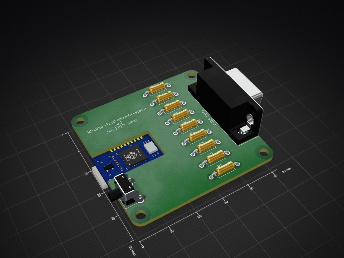
RP2040-TestPatternGenerator VGA is an open-source printed circuit board by nmur, from the nmur/RP2040-TestPatternGenerator repository on GitHub, published under the GPL-3.0 licence. It is a 2-layer board of 52 × 50 mm with 12 parts on 34 nets, routed with 58 tracks and 0 vias.
It is built around the RP2040-ZERO. Its parts include 9 resistors, 1 IC and 1 switch. It belongs with the RP2040 boards of this library.
This is a simple test pattern generator that runs on the RP2040 microcontroller. It uses the PicoVGA cmake library for outputting a 15kHz 240p RGBS signal via a VGA connector. This tool is aimed to be used for rudimentary tests for checking basic CRT TV functionality, not for accurate calibration.
Its main features are:
This program can only output colours in the RGB332 space, so each of the three colour channels (Red, Green, and Blue) are represented by 3, 3, and 2 bits, respectively. More information can be found here.
RP2040-TestPatternGenerator.uf2 file onto the device. It should automatically close when completed.cmake .make| Qty | Value | Footprint | References |
|---|---|---|---|
| 3 | 1K | Resistor_THT:R_Axial_DIN0207_L6.3mm_D2.5mm_P10.16mm_Horizontal | R1, R4, R7 |
| 2 | 2K2 | Resistor_THT:R_Axial_DIN0207_L6.3mm_D2.5mm_P10.16mm_Horizontal | R3, R6 |
| 2 | 470 | Resistor_THT:R_Axial_DIN0207_L6.3mm_D2.5mm_P10.16mm_Horizontal | R5, R8 |
| 1 | 100 | Resistor_THT:R_Axial_DIN0207_L6.3mm_D2.5mm_P10.16mm_Horizontal | R9 |
| 1 | 390 | Resistor_THT:R_Axial_DIN0207_L6.3mm_D2.5mm_P10.16mm_Horizontal | R2 |
| 1 | DE15_Receptacle_HighDensity_MountingHoles | Connector_Dsub:DSUB-15-HD_Female_Horizontal_P2.29x1.98mm_EdgePinOffset3.03mm_Housed_MountingHolesOffset4.94mm | RGBS OUT |
| 1 | SW_Push | Button_Switch_THT:SW_Tactile_SPST_Angled_PTS645Vx58-2LFS | SW1 |
| 1 | rp2040-zero | kleeb:rp2040-zero-smd | U1 |
It measures 52 × 50 mm and has 2 copper layers, 1.6 mm thick.
12 parts, built around the RP2040-ZERO. The full list of its parts is on this page, with links to each part's symbol and footprint where PCBKit's library has them.
From the nmur/RP2040-TestPatternGenerator repository on GitHub, at the commit this page was made from: the board is sch/RP2040-TestPatternGenerator-VGA.kicad_pcb and its schematic sch/RP2040-TestPatternGenerator-VGA.kicad_sch. PCBKit opens the board in the browser, with nothing to install.
Its repository publishes it under the GPL-3.0 licence: you may reuse it on that licence's terms (keep the author's notice, and for a copyleft licence share your changes alike).


beekeeb/zerosprey42
Zerosprey42 Keyboard is a wired, beginner friendly, choc hotswap, MonoBlockSplit (Unibody), column-staggered, DIY mechanical keyboard.


ravinrabbid/DonCon2040
RP2040 based firmware and hardware for DIY Taiko no Tatsujin Drum Controllers

ChrisChrisLoLo/bunchiez40
A pocket keyboard that makes use of mouse switches to achieve a miniscule size

