2 layers34 × 71.8 mm

 zouppen/virtaboksi
12/24/48V power switch for solar powered applications
Virtaboksi is an open-source printed circuit board by zouppen, from the zouppen/virtaboksi repository on GitHub. It is a 2-layer board of 50 × 72 mm with 66 parts on 52 nets, routed with 312 tracks and 48 vias.
It is built around the STM8S003F3P6, SRV05-4 and SP3485EN-Y, with the IRF4905, ZMM5V6-MS and MMBT3906 among its other parts. Its parts include 19 resistors, 13 transistors, 8 diodes, 7 connectors and 5 ICs. It belongs with the STM8 boards of this library.


Virtaboksi is a multi-purpose 3-channel common-earth power switch, rating 12–48 VDC, 20 A. It has multiple operating modes:
Home/away switch supporting three individual groups and is optimized for solar energy off-grid applications.
Water pump controller with pressure sensor input and control for combined submersible and pressure pump system. Additionally, a throw-over switching capability to drop loads while pumping.
Generic Modbus RTU server (slave) with 3 solid-state "coils", 3 digital outputs, and 4 digital inputs.
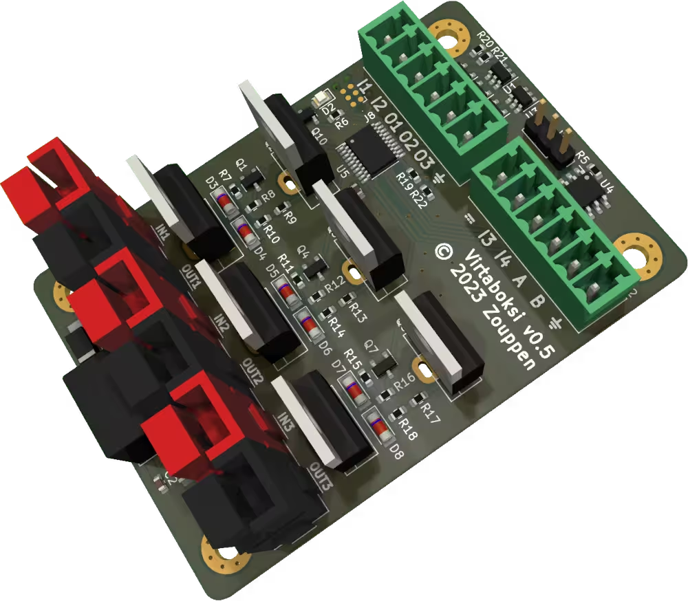
In the picture above the Powerpole connector colors are incorrect. Red is used for inputs and black for outputs. In a real product, the three groups have different colors: red, yellow and blue.
Status: 💚 Functional
This unit provides priority output on OUT1 when the switch is in either home or away position. Home controls OUT2 and OUT3 groups and can be used to control two separate voltages as long as they have a common ground.
An example use case is a solar off-grid system with two 12V batteries in series providing 24 volts, plus 12 volts generated from 24V using a step-down DC converter. DC converter is not included in the package.
In that case this switch can be used to turn the loads partially while being away, such as keeping refrigerator running but turning off lights while not present. When using a DC converter, its input is connected OUT1 its output (12V) to IN3.
Maximum voltage in IN1 is 34 VDC. The limitation comes from the internal power supply. In case you want to use higher voltages in IN1, cut the trace F1 on the bottom of this board and power the system directly from a regulated 3.3 VDC supply via the terminals.
IN2 and IN3 are rated for 60 volts maximum, making it possible to control 48V nominal voltage loads. Minimum voltage for all groups is about 10 volts. Under 10 volts, MOSFET control becomes unreliable.
In home/away mode, when I1 is shorted to the ground, the oprating mode is away. When I2 is shorted, the mode is home. If both connectors are open, operating mode is off.
Optionally, LED anodes can be connected directly to O1 and O2. They represent home and away operating modes, in that order. There is a current limiter controllable by R1 to limit the maximum current of O1...O3 to about 15 mA by default, so series resistors are not needed.
If your solar controller has a low battery condition relay, it can be connected to I3. When the input is high, the system is forced to off mode, ignoring the state of home/away switch.
I4 is not used in this mode.
Status: 🔬 Hardware OK
Hardware is capable, but no firmware support yet.
Status: 🔬 Hardware OK
RS-485 hardware is tested and some firmware tests performed, but no Modbus implementation exists yet.
To build firmware, you need CMake and sdcc. The preparations are very
standard CMake stuff. In firmware subdirectory, run:
mkdir build
cd build
cmake ..
And then, make compiles it. Alternatively, make upload to compile
and flash.
The firmware is free software: you can redistribute it and/or modify it under the terms of the GNU Affero General Public License as published by the Free Software Foundation, either version 3 of the License, or (at your option) any later version.
The hardware is provided as source-available: The schematics and PCB layout are provided for reference only. The files can be freely distributed without limitations but no derivative works are allowed without a permission from the copyright holders.
| Qty | Value | Footprint | References |
|---|---|---|---|
| 6 | 10 | Resistor_SMD:R_0603_1608Metric | R9, R10, R13, R14, R17, R18 |
| 6 | Heatsink | Own parts:Heatsink_AAVID_576802B03900G-nocourt | HS1, HS2, HS3, HS4, HS5, HS6 |
| 6 | IRF4905 | Package_TO_SOT_THT:TO-220-3_Vertical | Q2, Q3, Q5, Q6, Q8, Q9 |
| 6 | ZMM5V6-M | Diode_SMD:D_MiniMELF | D3, D4, D5, D6, D7, D8 |
| 4 | 5k | Resistor_SMD:R_0603_1608Metric | R19, R20, R21, R22 |
| 4 | MMBT3906 | Package_TO_SOT_SMD:SOT-23 | Q10, Q11, Q12, Q13 |
| 4 | MountingHole_Pad | MountingHole:MountingHole_3.2mm_M3_Pad_Via | H1, H2, H3, H4 |
| 3 | 13k | Resistor_SMD:R_0603_1608Metric | R8, R12, R16 |
| 3 | 2N7002 | Package_TO_SOT_SMD:SOT-23 | Q1, Q4, Q7 |
| 3 | 68k | Resistor_SMD:R_0603_1608Metric | R7, R11, R15 |
| 3 | Powerpole 01x02 | Powerpole:45A-VERT-PAIR | J5, J6, J7 |
| 2 | 220 | Resistor_SMD:R_0603_1608Metric | R1, R6 |
| 2 | SRV05-4 | Package_TO_SOT_SMD:SOT-23-6 | U1, U3 |
| 1 | 10u | Capacitor_SMD:C_1206_3216Metric | C1 |
| 1 | 1u | Capacitor_SMD:C_0603_1608Metric | C3 |
| 1 | 20k | Resistor_SMD:R_0603_1608Metric | R5 |
| 1 | 22u | Capacitor_SMD:C_0603_1608Metric | C2 |
| 1 | AMSRI-783.3-NZ | Converter_DCDC:Converter_DCDC_RECOM_R-78E-0.5_THT | U2 |
| 1 | External_01x06 | Connector_Phoenix_MC:PhoenixContact_MCV_1,5_6-G-3.5_1x06_P3.50mm_Vertical | J2 |
| 1 | Fuse | Own parts:Fuse-kindof_1x02_P3.6mm_D0.4mm_OD1mm | F1 |
| 1 | LED | LED_SMD:LED_0805_2012Metric | D2 |
| 1 | Optional_01x03 | Connector_PinHeader_2.54mm:PinHeader_1x03_P2.54mm_Vertical | J3 |
| 1 | Panel_01x06 | Connector_Phoenix_MC:PhoenixContact_MCV_1,5_6-G-3.5_1x06_P3.50mm_Vertical | J1 |
| 1 | SMAJ33A | Diode_SMD:D_SMA_Handsoldering | D1 |
| 1 | SP3485EN | Package_SO:SOIC-8_3.9x4.9mm_P1.27mm | U4 |
| 1 | STM8S003F3P | Package_SO:TSSOP-20_4.4x6.5mm_P0.65mm | U5 |
| 1 | TagConnect_TC2030-NL | Connector:Tag-Connect_TC2030-IDC-NL_2x03_P1.27mm_Vertical | J8 |
It measures 50 × 72 mm and has 2 copper layers, 1.6 mm thick.
66 parts, built around the STM8S003F3P6, SRV05-4, SP3485EN-Y and IRF4905. The full list of its parts is on this page, with links to each part's symbol and footprint where PCBKit's library has them.
From the zouppen/virtaboksi repository on GitHub, at the commit this page was made from: the board is virtaboksi.kicad_pcb and its schematic mosfet.kicad_sch. PCBKit opens the board in the browser, with nothing to install.
Its repository states no licence, so its author keeps all rights: ask zouppen before reusing the design.


Neotron-Compute/Neotron-Common-Hardware
Contains KiCad footprints and symbols shared across multiple Neotron projects.

OpenLogicEFI/Hardware
Hardware is based off an open source project called Speeduino by Josh Stewart.


ControlSystemIntegrators/Therm_temp_4_20_xmtr
Fully analog 2-wire 4-20 mA NTC thermistor temperature transmitter, built from multi-sourced parts — plus an instrumentation-theory tutorial. Default build: 20-40 C for chocolate temperature control.
