2 layers77 × 39 mm

 zetapersei/Wifi-ATmega328
Simple board with esp8266 + ATMega328
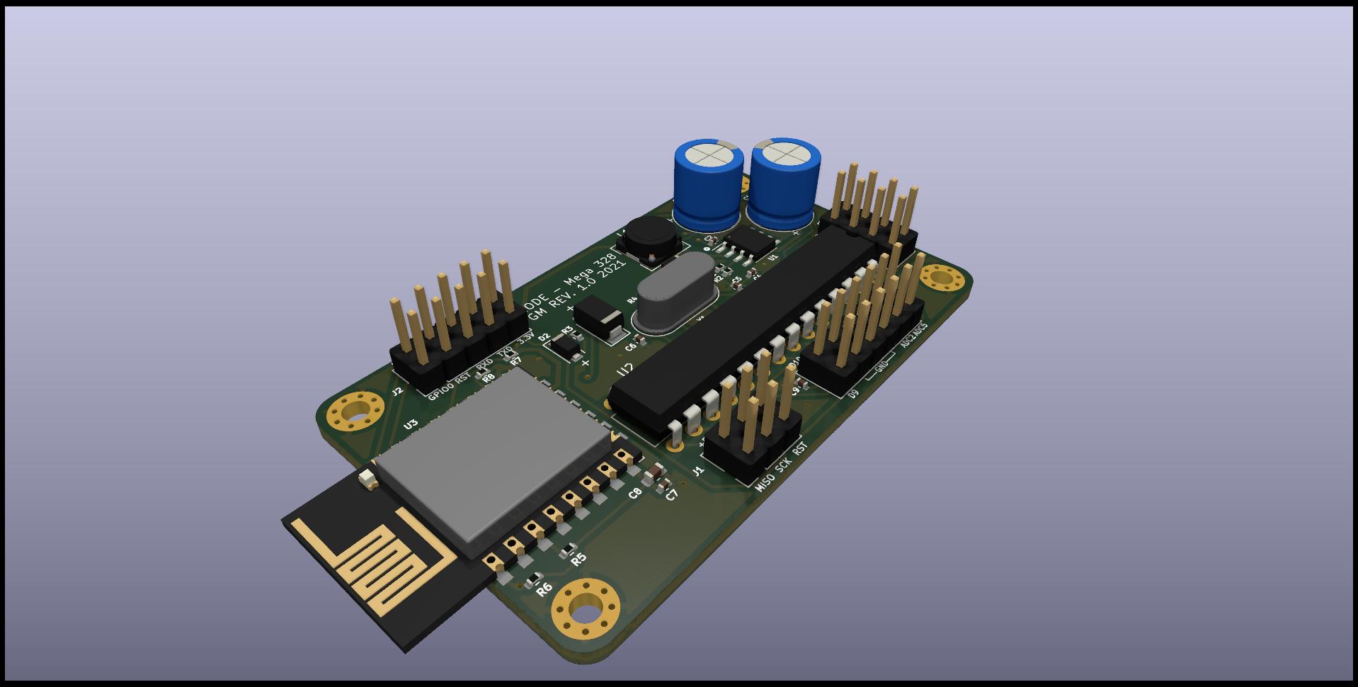
RIO Mega-328 is an open-source printed circuit board by zetapersei, from the zetapersei/Wifi-ATmega328 repository on GitHub, published under the GPL-3.0 licence. It is a 2-layer board of 61 × 36 mm with 33 parts on 52 nets, routed with 341 tracks and 21 vias.
It is built around the ATMEGA328P-PU, ESP-12F and XL1509-ADJE1, with the B5819W among its other parts. Its parts include 9 capacitors, 8 resistors, 4 connectors, 3 ICs and 3 diodes. It belongs with the ESP8266 and AVR (ATmega, ATtiny) boards of this library.


A compact embedded board that combines an ESP8266 Wi-Fi module with an ATmega328P microcontroller for projects that need low-cost wireless connectivity and simple MCU control.
This project provides a custom PCB designed for applications where an ATmega328P handles the logic and an ESP8266 provides Wi-Fi communication. The design is intended for embedded systems, IoT prototypes, sensor gateways, and small control boards that need a lightweight microcontroller plus wireless connectivity.
The board includes:
The board is built around two processing elements:
The supplied power stage converts the board supply into the voltage levels required by the modules. A dedicated ICSP connector allows the ATmega328P to be programmed directly without removing it from the board.
The hardware project is available in the hardware folder and includes the KiCad schematic and PCB files.
The ESP8266 can be used with the AT command firmware, enabling communication with the ATmega328P through serial interfaces. In this setup, the MCU can delegate Wi-Fi tasks to the ESP8266 while continuing to handle local logic.
Recommended software paths:
This makes the board suitable for both classic serial-controlled Wi-Fi use and low-latency peer-to-peer wireless communication.
hardware/ — KiCad project files and PCB design assetsREADME.md — project overview and documentationLICENSE — project license information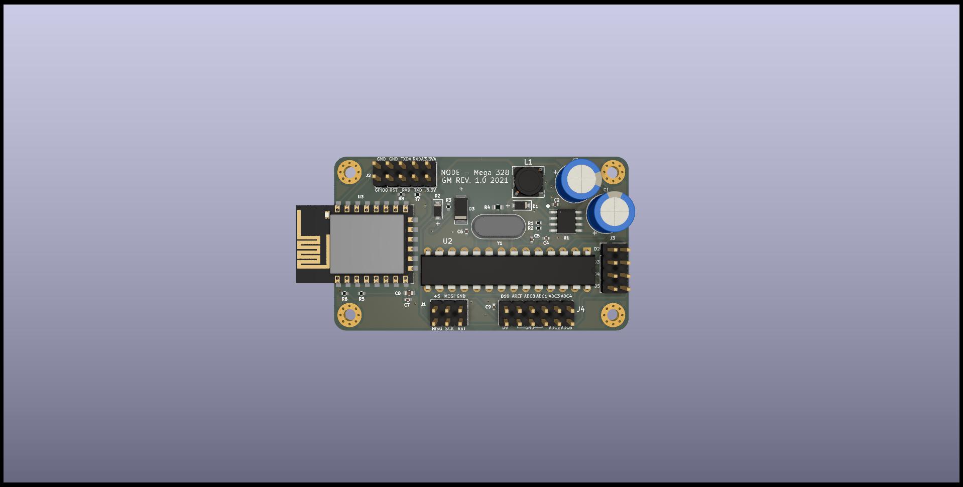
This board is especially useful when an AVR-based firmware stack is preferred while still requiring network connectivity through the ESP8266.
| Qty | Value | Footprint | References |
|---|---|---|---|
| 5 | 10k | Resistor_SMD:R_0402_1005Metric | R3, R5, R6, R7, R8 |
| 4 | 100nF | Capacitor_SMD:C_0402_1005Metric | C2, C4, C7, C9 |
| 4 | MountingHole_Pad | MountingHole:MountingHole_2.5mm_Pad_Via | H1, H2, H3, H4 |
| 2 | 22pF | Capacitor_SMD:C_0402_1005Metric | C5, C6 |
| 1 | 1.8k | Resistor_SMD:R_0402_1005Metric | R2 |
| 1 | 10uF | Capacitor_SMD:C_0603_1608Metric | C8 |
| 1 | 16Mhz | Crystal:Crystal_HC18-U_Vertical | Y1 |
| 1 | 1M | Resistor_SMD:R_0603_1608Metric | R4 |
| 1 | 1N4148 | Diode_SMD:D_SOD-123F | D2 |
| 1 | 1k | Resistor_SMD:R_0402_1005Metric | R1 |
| 1 | 330uF/35V | Capacitor_THT:CP_Radial_D8.0mm_P5.00mm | C3 |
| 1 | 470uF/35V | Capacitor_THT:CP_Radial_D8.0mm_P5.00mm | C1 |
| 1 | 47uH/2A | JLCPCB:L_6.0x6.0x4.5-SWPA-Sunlord | L1 |
| 1 | ATmega328P-PU | Package_DIP:DIP-28_W7.62mm | U2 |
| 1 | B5819W | Diode_SMD:D_SOD-123F | D1 |
| 1 | ESP Prog | Connector_PinHeader_2.54mm:PinHeader_2x05_P2.54mm_Vertical | J2 |
| 1 | ESP-12F | RF_Module:ESP-12E | U3 |
| 1 | GPIO1 | Connector_PinHeader_2.54mm:PinHeader_2x04_P2.54mm_Vertical | J3 |
| 1 | GPIO2 | Connector_PinHeader_2.54mm:PinHeader_2x06_P2.54mm_Vertical | J4 |
| 1 | ICSP | Connector_PinHeader_2.54mm:PinHeader_2x03_P2.54mm_Vertical | J1 |
| 1 | M7 | Diode_SMD:D_SOD-128 | D3 |
| 1 | XL1509-ADJE1 | Package_SO:SOP-8_3.9x4.9mm_P1.27mm | U1 |

cjheath/STM32C071_Basic
A basic template for prototype boards using the STM32F071 as a USB controller


LECTIX/LEC000042-Detecteur-de-presence-DCC-Analogique-1A
Fichiers sources pour le produit LEC000042


NilsEngelbach/air-quality-pcb
Seventh iteration: ESP8266 → ESP32-C3 (native USB, no UART bridge), fixes from the v6 design review, right-angle switches with longer actuators, a STEMMA QT port for optional sensors, and charge-status sensing.
It measures 61 × 36 mm and has 2 copper layers, 1.6 mm thick.
33 parts, built around the ATMEGA328P-PU, ESP-12F, XL1509-ADJE1 and B5819W. The full list of its parts is on this page, with links to each part's symbol and footprint where PCBKit's library has them.
From the zetapersei/Wifi-ATmega328 repository on GitHub, at the commit this page was made from: the board is hardware/RIO-Mega-328.kicad_pcb and its schematic hardware/RIO-Mega-328.kicad_sch. PCBKit opens the board in the browser, with nothing to install.
Its repository publishes it under the GPL-3.0 licence: you may reuse it on that licence's terms (keep the author's notice, and for a copyleft licence share your changes alike).