2 layers50 × 25 mm
STM32C071
cjheath/STM32C071_Basic
A basic template for prototype boards using the STM32F071 as a USB controller
18 parts2
 TimGoll/pcb_buck_test1
Four different buck circuits on a single PCB benchmarked
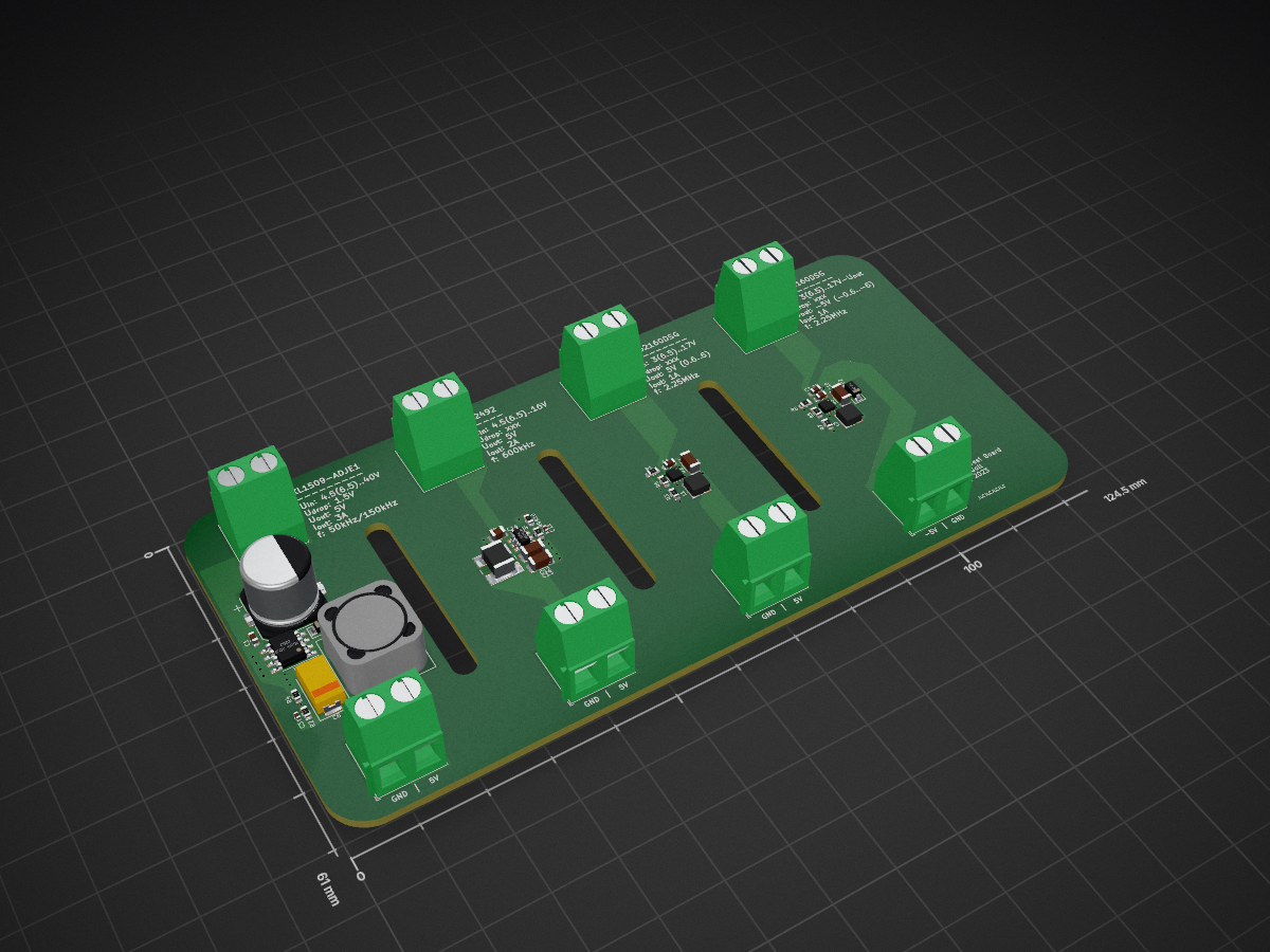
Buck test is an open-source printed circuit board by TimGoll, from the TimGoll/pcb_buck_test repository on GitHub, published under the MIT licence. It is a 4-layer board of 124.5 × 61 mm with 42 parts on 20 nets, routed with 84 tracks and 39 vias.
It is built around the TPS62160DSG, MT2492 and XL1509-ADJE1, with the DSK34 among its other parts. Its parts include 14 capacitors, 10 resistors, 8 connectors, 4 ICs and 4 inductors. It belongs with the power boards of this library.


To get an understanding of different buck ICs and their drawbacks and benefits I designed this PCB. While all of them worked, some performed better than others. To verify my first impressions while initial testing I benchmarked the ICs over different voltages and currents.
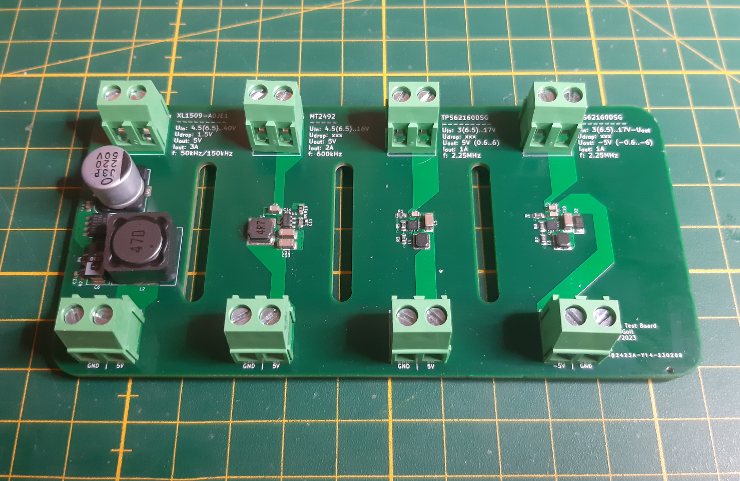 (the four different buck circuits that I tested)
4.5..40V1.23..37V (fixed versions available too)2A50kHz/150kHz4.5..16V0.8..15V2A600kHz3..17V0.9..6V (fixed versions available too)1A2.25MHz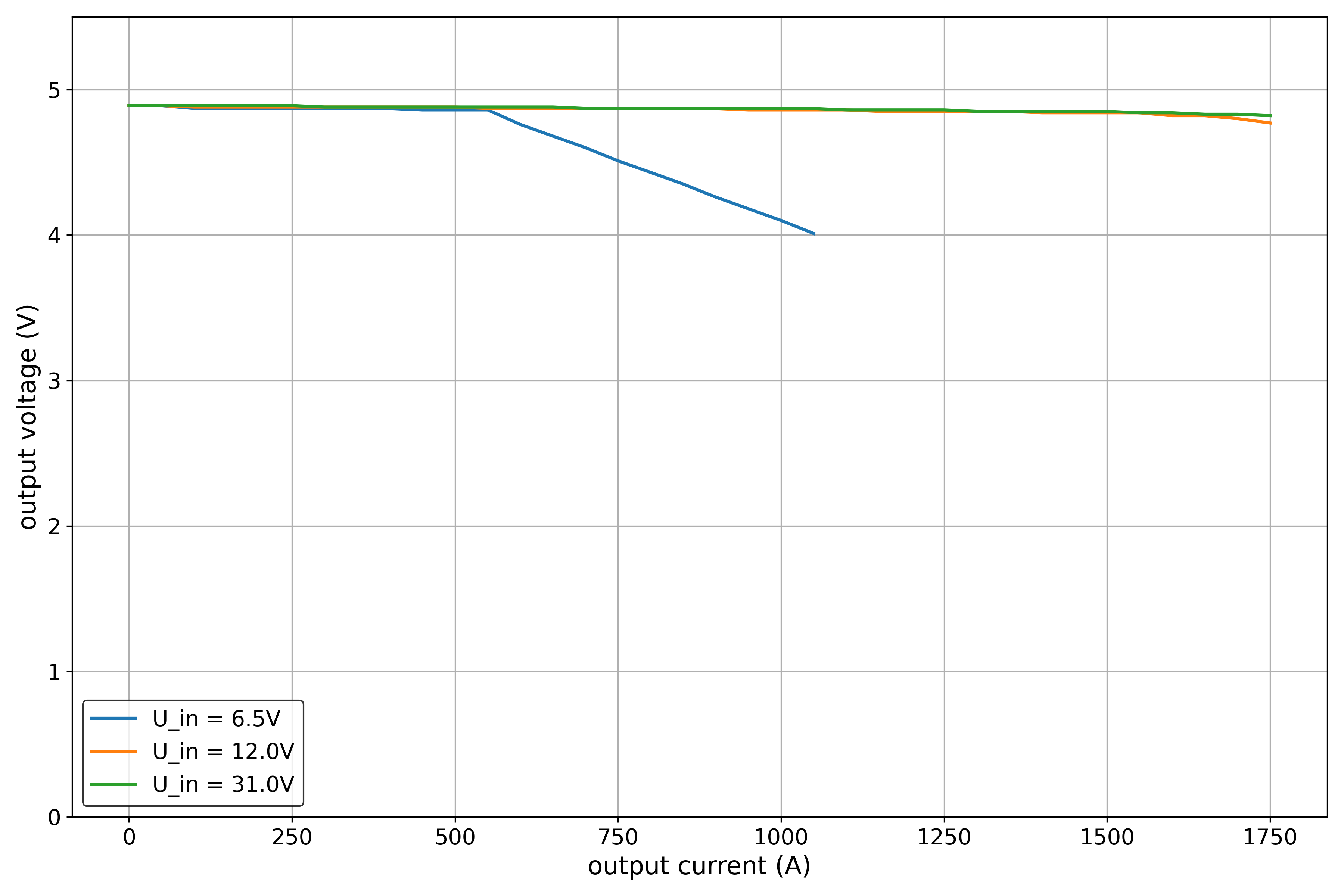 (output voltage vs different output currents)
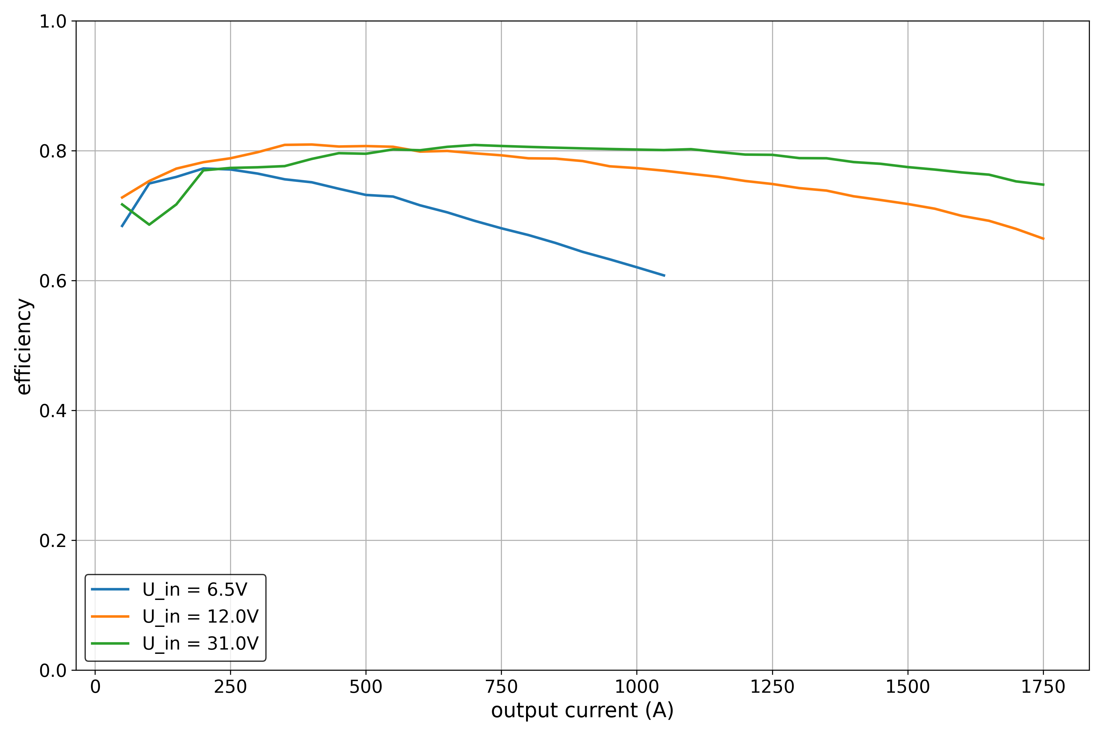 (efficiency vs different output currents)
While this IC is very cheap and has a wide range of input voltages, everything else about it isn't worth it. The low switching frequency is the reason for the huge passive components that have to be added around this IC. This negates the benefit of its price since the required components are rather expensive.
Moreover this IC really struggled with thermals. I had to stop the tests at 1750mA due to the output becoming instable because the IC overheated.
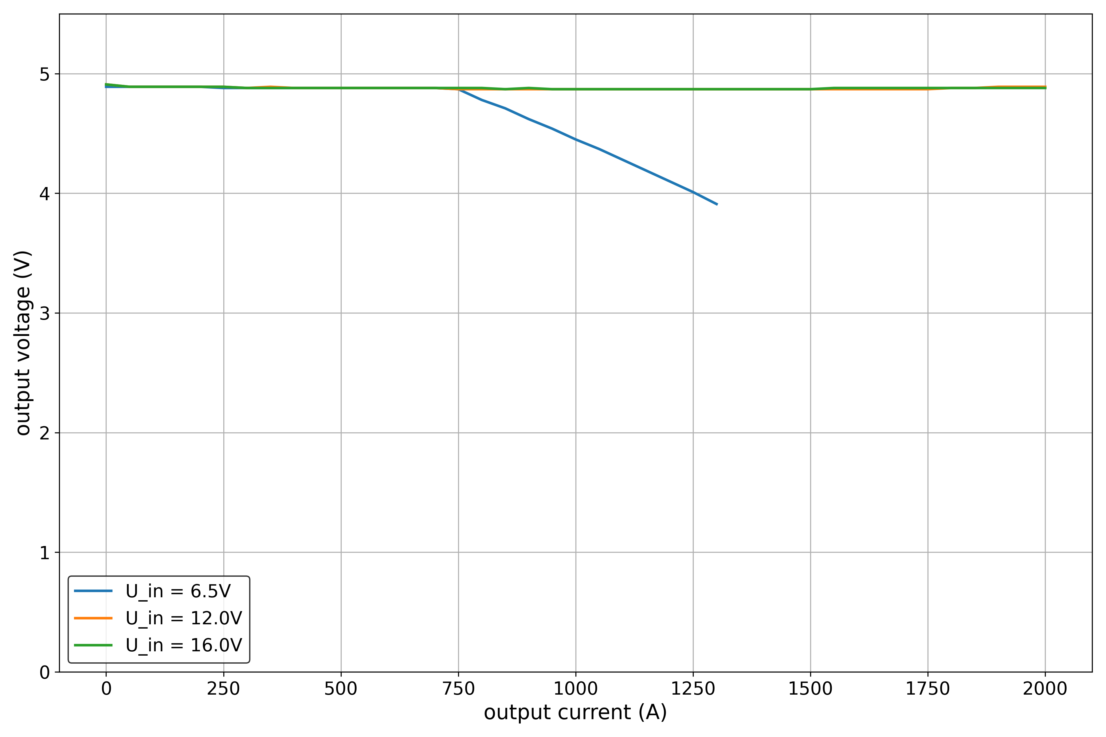 (output voltage vs different output currents)
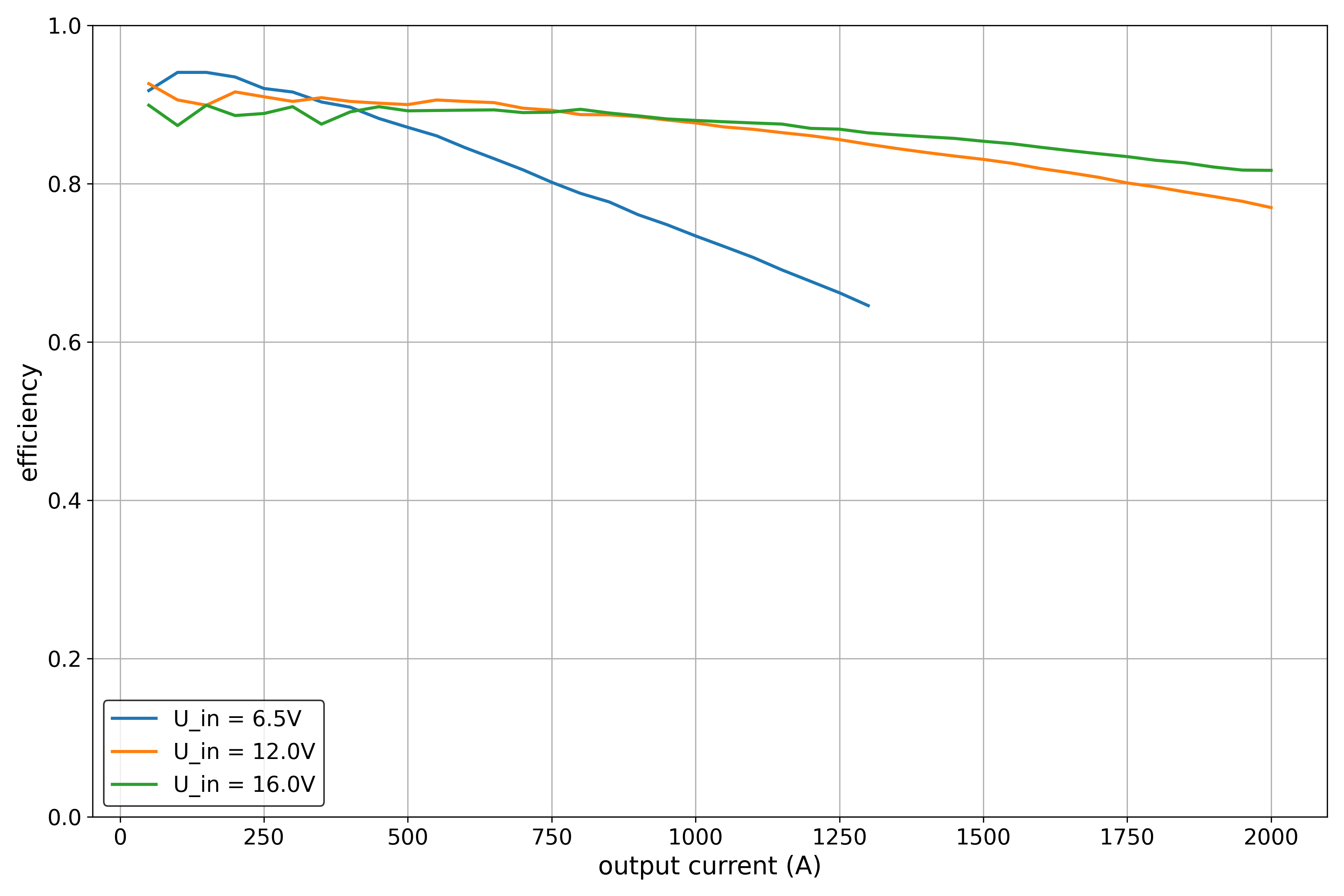 (efficiency vs different output currents)
The MT2492 is a cheap and less capable copy of the MP2492 by MPS. It comes in a small package that combined with the smaller passive components needs very little space on the PCB.
Its efficiency is rather good and the output voltage is stable. Even over the time of multiple minutes the IC did not overheat when 2A were pulled.
All in all this is a good IC when more than 1A of continuous current is needed.
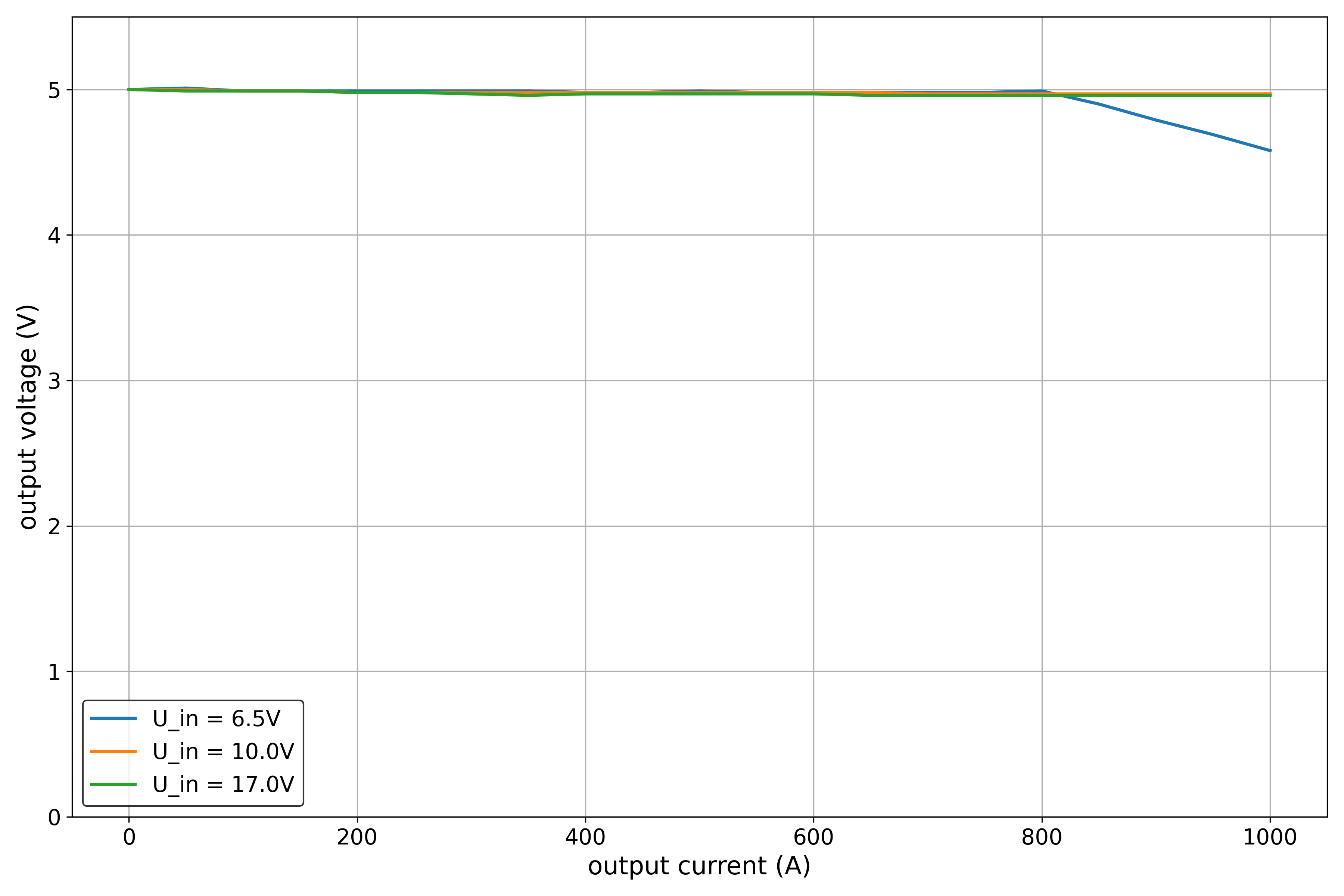 (output voltage vs different output currents)
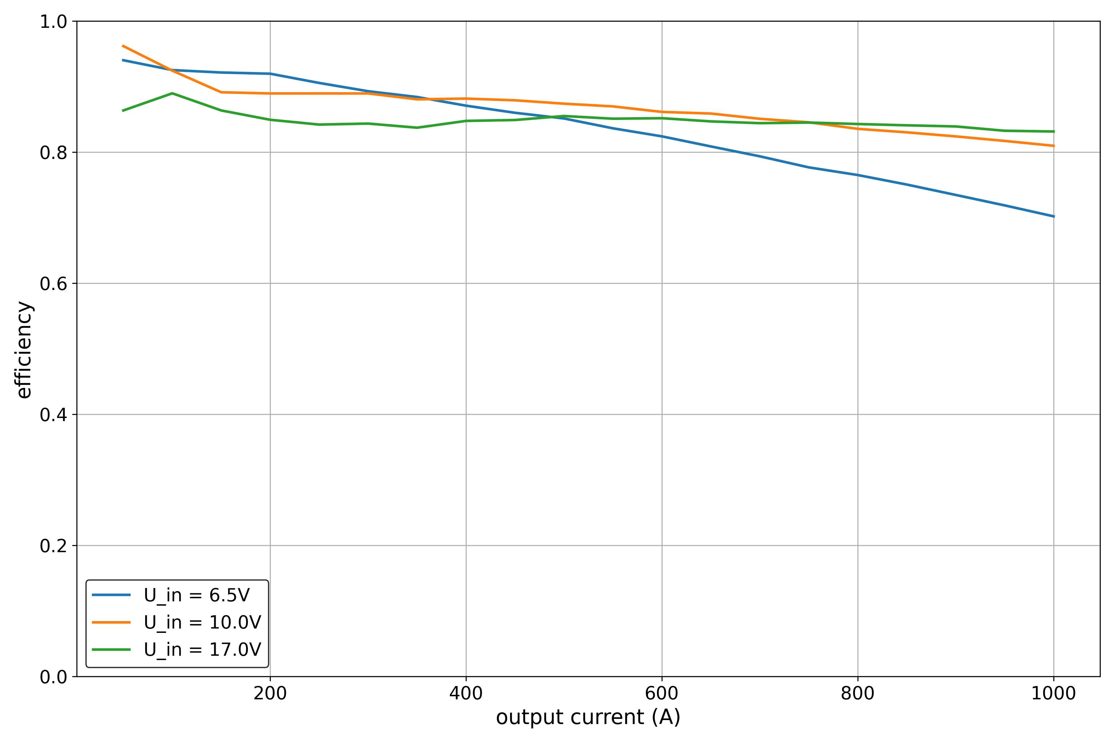 (efficiency vs different output currents)
This IC made by TI is the smalles of them all. Paired with its high switching frequency the overall footprint of the circuit is really small. The output voltage is very stable, even for small drops and rather high currents. The efficiency is very good as well.
This is the best of the bunch, even though it is a bit more expensive. The most impressive thing is that it did not overheat, even though my thermal design for this circuit was very bad.
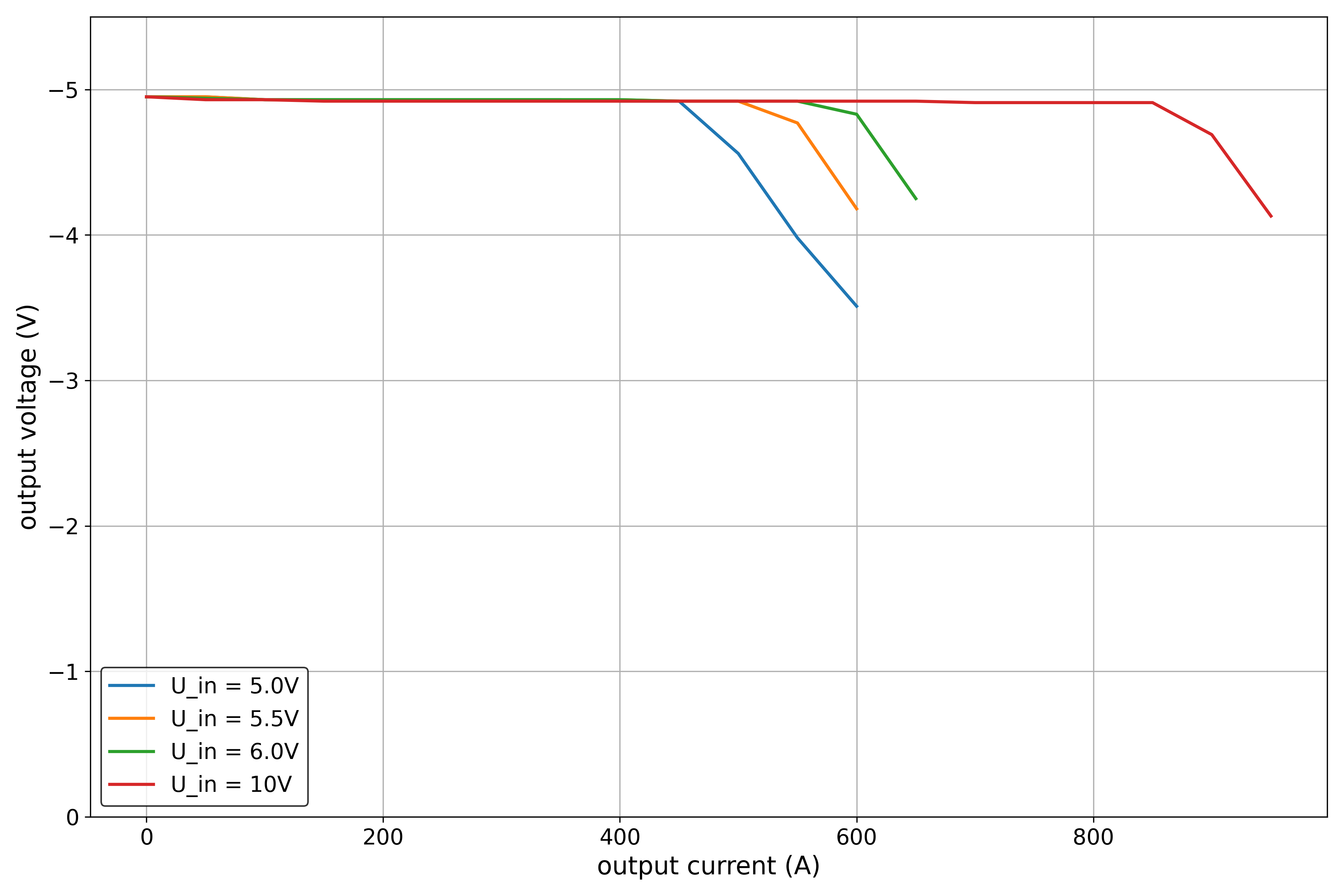 (output voltage vs different output currents)
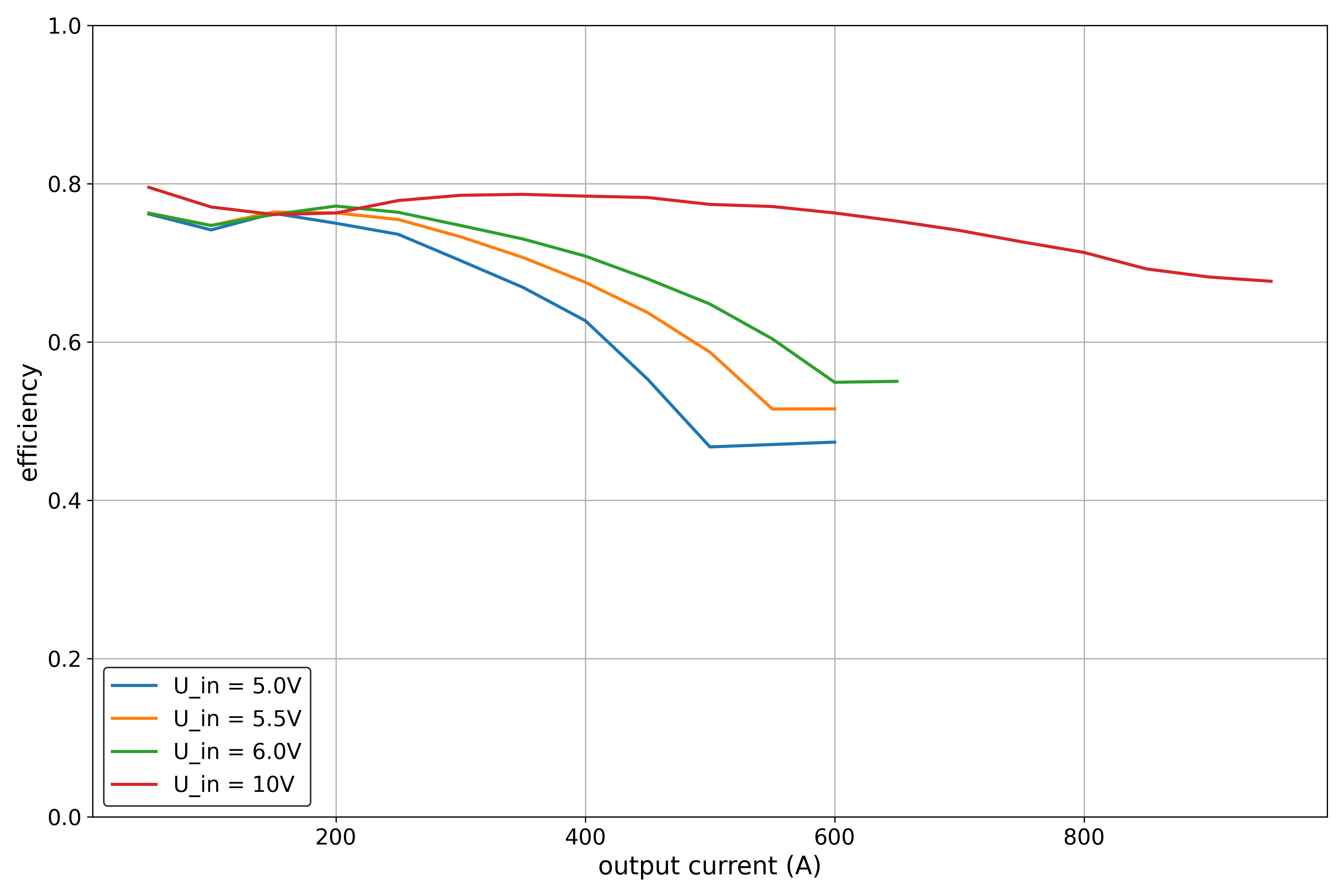 (efficiency vs different output currents)
The same IC from the previous test was used again, but in a special configuration. With the addition of a few further passive components this IC can be used as an inverted power supply. While the input voltage range is decreased that way, the overall performance is still great.
One thing to highlight that it is possible to get stable -5V from a 5V source for up to 450mA of continous current. This makes this IC great for the use in OpAmp circuits where a negative rail is needed.
A minor drawback is that the efficiency is greatly reduced.
| Qty | Value | Footprint | References |
|---|---|---|---|
| 8 | Conn_01x02 | TerminalBlock_Phoenix:TerminalBlock_Phoenix_MKDS-1,5-2-5.08_1x02_P5.08mm_Horizontal | J1, J2, J3, J4, J5, J6, J7, J8 |
| 4 | 22u 10V | Capacitor_SMD:C_1206_3216Metric | C5, C10, C12, C13 |
| 3 | 10u 25V | Capacitor_SMD:C_0603_1608Metric | C4, C7, C9 |
| 2 | 100k | Resistor_SMD:R_0603_1608Metric | R1, R6 |
| 2 | 130k | Resistor_SMD:R_0603_1608Metric | R5, R8 |
| 2 | 2u2 1..3A | Inductor_SMD:L_Wuerth_MAPI-3015 | L1, L3 |
| 2 | 680k | Resistor_SMD:R_0603_1608Metric | R3, R7 |
| 2 | DSK34 | Diode_SMD:D_SOD-123 | D1, D2 |
| 2 | TPS62160DSG | Package_SON:WSON-8-1EP_2x2mm_P0.5mm_EP0.9x1.6mm_ThermalVias | U2, U3 |
| 1 | 110k | Resistor_SMD:R_0603_1608Metric | R9 |
| 1 | 15k | Resistor_SMD:R_0603_1608Metric | R10 |
| 1 | 1k | Resistor_SMD:R_0603_1608Metric | R4 |
| 1 | 1u | Capacitor_SMD:C_0603_1608Metric | C1 |
| 1 | 220u 10V 25mR | Capacitor_Tantalum_SMD:CP_EIA-7343-31_Kemet-D | C6 |
| 1 | 220u 50V | Capacitor_SMD:CP_Elec_10x10 | C2 |
| 1 | 22n | Capacitor_SMD:C_0402_1005Metric | C14 |
| 1 | 22p | Capacitor_SMD:C_0402_1005Metric | C11 |
| 1 | 22u 25V | Capacitor_SMD:C_0805_2012Metric | C8 |
| 1 | 3k | Resistor_SMD:R_0603_1608Metric | R2 |
| 1 | 3n3 | Capacitor_SMD:C_0402_1005Metric | C3 |
| 1 | 47u 3A | Inductor_SMD:L_12x12mm_H8mm | L2 |
| 1 | 4u7 2A | Inductor_SMD:L_Wuerth_WE-PD2-Typ-MS | L4 |
| 1 | MT2492 | Package_TO_SOT_SMD:SOT-23-6 | U4 |
| 1 | XL1509-ADJE1 | Package_SO:SOIC-8_3.9x4.9mm_P1.27mm | U1 |
cjheath/STM32C071_Basic
A basic template for prototype boards using the STM32F071 as a USB controller

LECTIX/LEC000042-Detecteur-de-presence-DCC-Analogique-1A
Fichiers sources pour le produit LEC000042


stanleyondrus/ILDAWaveX16
ILDAWaveX16 is an open-source, high-resolution, wireless laser DAC with SD-card playback, network control, and ILDA output.


Legohead259/Vacuum-Tweezers-ECAD
KiCAD repository for the electrical designs for the SL_ST vacuum tweezer design
It measures 124.5 × 61 mm and has 4 copper layers, 1.6 mm thick.
42 parts, built around the TPS62160DSG, MT2492, XL1509-ADJE1 and DSK34. The full list of its parts is on this page, with links to each part's symbol and footprint where PCBKit's library has them.
From the TimGoll/pcb_buck_test repository on GitHub, at the commit this page was made from: the board is buck_test/buck_test.kicad_pcb and its schematic buck_test/buck_test.kicad_sch. PCBKit opens the board in the browser, with nothing to install.
Its repository publishes it under the MIT licence: you may reuse it on that licence's terms (keep the author's notice, and for a copyleft licence share your changes alike).