
4 layers30.5 × 68.6 mm

 Yorha-7/Rocket
in this repo we are simulating rocket basic physics and make a onboard flight computer which utilizes MCU, gyro, pressure sensor, fin servo controls, to get realtime target tracking abilities to a solid fuel rocket.
Schmatic is an open-source printed circuit board by Yorha-7, from the Yorha-7/Rocket repository on GitHub. It is a 2-layer board of 65 × 65.5 mm with 77 parts on 76 nets, routed with 461 tracks and 72 vias.
It is built around the STM32F103C8T6, MS561101BA03-50 and AMS1117, with the BQ24074RGTT, MPU-9250 and GZ2012D121TF among its other parts. Its parts include 29 capacitors, 22 resistors, 6 connectors, 5 ICs and 3 diodes. It belongs with the sensors and measurement and robots and motor control boards and the STM32 boards of this library.


This repo is one project told in three layers: a physics simulation that
predicts how a rocket actually flies, a flight-computer stack (sensors +
guidance + a gimbaled nozzle) that steers it, and the hardware (PCB,
motor, airframe) that would eventually fly for real. The simulation
(sim/rocket_cpp/) is the part that's actually working today and the focus of
this document.
If you don't have an aerospace background, that's fine — every technical term below is explained the first time it shows up, and Appendix A is a full glossary you can jump to any time something's unclear.
ork/: reading the rocket back out of OpenRocketsim/: the physics enginegnc/: sensors, guidance, and the gimbalOpenRocket is the standard free tool for designing and simulating model rockets — you build up a rocket's geometry (nose cone, body tube, fins), pick a motor, and it simulates the flight for you. It's excellent at that. But it only simulates passive flight: the rocket is a fixed shape with fixed fins, and the only thing steering it is whatever natural aerodynamic stability that shape has. There's no way to model a rocket that can sense its own attitude and actively push itself back on course mid-flight.
That's exactly the gap this project fills. The goal was a rocket that carries a gimbaled (steerable) nozzle — one that can tilt the direction of its thrust in real time, the same basic idea SpaceX boosters use — and a small onboard "brain" that decides, moment to moment, which way to point it so the rocket flies toward a chosen target instead of wherever its fins happen to point it.
Since no existing free tool simulates that, the design here uses each tool for what it's actually good at:
.ork file — no reason
to reinvent rocket CAD.sim/rocket_cpp/), built from scratch, because that
piece genuinely didn't exist anywhere else.The simulator is organized into three modules that mirror three physically
distinct jobs. Each one lives in its own folder under sim/rocket_cpp/include/
and sim/rocket_cpp/src/:
flowchart LR
ork(["rocket.ork<br/>geometry, motor thrust & mass curve"])
subgraph SIM["sim/ — physics engine"]
physics["own aero coefficients<br/>own kinematics & torques"]
end
subgraph GNC["gnc/ — flight computer"]
direction TB
sensors["Sensors"] --> nav["Navigation<br/>(guidance)"] --> tvc["ThrustVectorControl"]
end
ork -->|"ork/"| physics
physics -->|"vehicle state"| sensors
tvc -->|"nozzle angle"| physicsork/ — a .ork file is really just a zip archive containing XML
(OpenRocket's save format). This module unzips it and reads out the
rocket's shape and its motor's thrust/mass-over-time curve.sim/ — the ground-truth physics engine. Given the vehicle's
shape and how the nozzle is currently pointed, this is what actually
computes forces, torques, and the resulting motion, step by step.gnc/ — short for Guidance, Navigation, and Control, the
standard aerospace term for "the flight computer stack." This is the
part that watches where the rocket is and decides how to move the
nozzle to correct course — the actively-controlled half of the project
that OpenRocket has no equivalent of at all.Every step of simulated flight flows through all three: sim/ computes
"what actually happened this instant," gnc/ reads that and decides "what
to do next," and that decision feeds back into sim/ for the following
step. That feedback loop — measure, decide, act, repeat — is what
closed-loop control means, and it's the whole reason this project
exists.
ork/: reading the rocket back out of OpenRocketOpenRocket's own file format bundles everything about a design into one
.ork file: body dimensions, nose shape, fin geometry, and — if you've run
a simulation inside OpenRocket itself — a full time history of that flight
too.
This project only trusts one thing out of that file: the motor's own thrust curve (thrust in newtons over time) and mass curve (how much the vehicle weighs as it burns propellant). That data comes from the motor manufacturer's own testing, not from OpenRocket's simulation, so there's no substitute for it — a solid rocket motor's thrust profile isn't something you can derive from first principles without literally burning one on a test stand.
Everything else about how the rocket flies — drag, stability, the turning forces air exerts on it — is deliberately not read from OpenRocket's own simulated results. It's recomputed independently in Stage 2, from the raw geometry alone. That was a real design decision, not laziness: this project needed those numbers available live, every physics step, responding to whatever the guidance system was doing to the vehicle at that instant — not a fixed, pre-solved number that assumed a passive, unguided flight.
sim/: the physics engineThis is the part that answers "given everything about the rocket right now, what happens in the next instant?" It runs every simulated step and knows nothing about guidance at all — it just faithfully computes physics from whatever nozzle angle it's told.
Forces. Three things push and pull on the rocket:
q = ½ρv² — a measure of how hard
the air is pushing, from air density ρ and airspeed v) times a drag
coefficient.Where the drag/turning coefficients come from. The air-density and speed-of-sound model is the ISA (International Standard Atmosphere — the standard formula relating altitude to pressure, temperature, and density). The aerodynamic coefficients themselves — how much drag, and how much sideways "normal force," a given shape produces — come from the Barrowman method, a set of formulas (from a 1966 NASA-adjacent paper by James Barrowman) that predict a model rocket's aerodynamics directly from its geometry: nose shape, fin count and shape, body diameter. It also computes the center of pressure (CP) — the single point where all that aerodynamic force can be treated as acting — purely from geometry.
Why the rocket tips over on its own. Every rigid body has a center of gravity (CG) — the point where its mass balances — and, for an aerodynamic body, that's normally in a different place than the CP. If the two are offset and the rocket's nose isn't pointed exactly along its direction of travel, that mismatch is called angle of attack (α) (in the fore-aft plane) and sideslip (β) (in the left-right plane) — and the aerodynamic force acting through the offset CP creates a torque (a rotational force, a twist) around the CG that tries to swing the nose back into the airflow. This self-correcting behavior is called weathercocking — the same reason a weathervane always points into the wind — and it's why a well-designed passive rocket (no guidance at all) still flies straight. This simulation models that torque for real, opposed by an aerodynamic damping torque (resistance proportional to how fast the rocket is already rotating, so it settles instead of oscillating forever), the same way OpenRocket's own flight model does.
Turning that into motion. Each step: sum the forces, divide by mass to get acceleration, integrate that into velocity and position (a numerical integration scheme called Euler integration — approximate the next instant using the current rate of change, repeated thousands of times a second). Sum the torques, divide by moment of inertia (a body's resistance to being spun, the rotational equivalent of mass) to get angular acceleration, and integrate that into rotation rate and orientation (pitch and yaw Euler angles — the standard "tip forward/back" and "swing left/right" attitude angles).
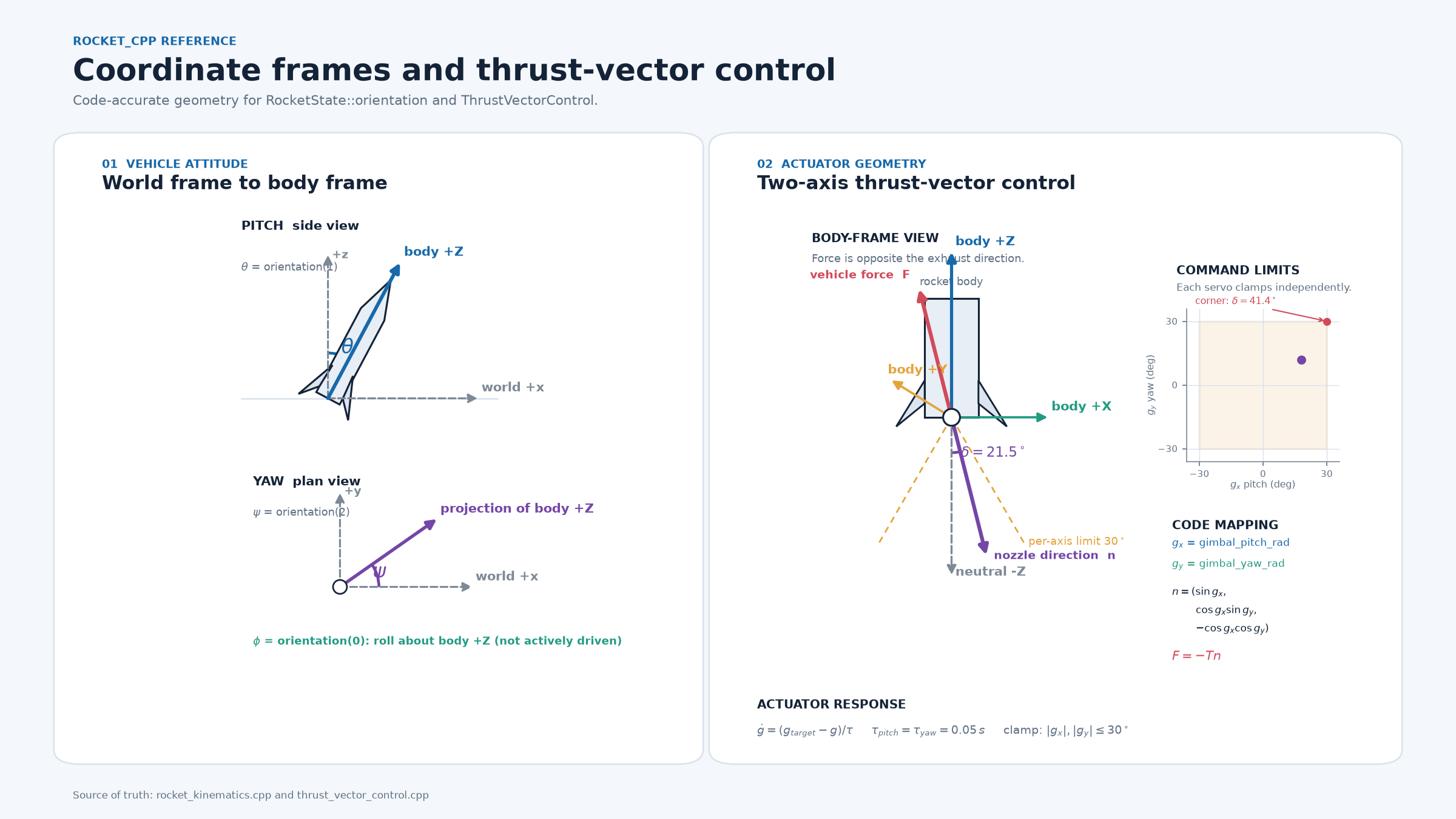
Translating between "the rocket's own point of view" (body frame — where +Z is the direction the nose is pointing) and "the world's point of view" (world frame — where +Z is straight up) is done with a rotation matrix called a DCM (Direction Cosine Matrix) built from those Euler angles. Thrust and drag are computed in the body frame (they naturally act along and against the vehicle's own axes) and then rotated into the world frame to actually move the rocket through space.
gnc/: sensors, guidance, and the gimbalThis is the layer with no OpenRocket equivalent — the part that makes this a controlled rocket instead of a passive one. Three pieces, each modeling a real physical part of a flight computer:
Sensors (Gyro, Baro, Gps) — simulated readings of the vehicle's
own true state: orientation and rotation rate (gyroscope), altitude
(barometer), and position (GPS). Today they read the simulation's own
ground truth directly, with no noise or bias modeled yet — the point is
to keep the interface realistic (a real flight computer can only ever
act on what its sensors report, never on the world's actual state
directly) so sensor imperfection can be layered in later without
restructuring anything above it.
Navigation — the guidance law. Every step, it works out the angle between where the nose is currently pointing and the direction to the target, and shapes that error through a PID controller — the standard feedback-control building block, one of the most widely used in all of engineering. Its three terms:
In this project's tuning, D turned out to hurt, not help — because
the gimbal actuator (next paragraph) already has its own built-in damping
from its physical lag, so an extra derivative term on top of it just
fought the correction instead of smoothing it. That's a real finding from
testing this specific vehicle, not a rule that holds for every control
system — see sim/rocket_cpp/include/gnc/navigation.hpp
for the actual numbers. Navigation also deliberately stays off below a
minimum altitude — right off the pad, a tiny angle error would otherwise
translate into a full steering command at the worst possible moment.
Navigation is now split into two classes: Navigation (a simple path
planner — breaks one final target into a straight-line sequence of
nearby waypoints) driving NavigationStep (the PID controller described
above) one waypoint at a time. The reason: a target close to the pad and
one far downrange ask the same fixed gain set for very different
maneuvers, so instead of retuning per-target, the planner makes every
step look like the same kind of local steering problem — see
sim/rocket_cpp/include/gnc/navigation.hpp.
sim/rocket_cpp/src/tuning/ is a separate, offline tool (pid_ga_tuner) that
searches for a better (Kp, Ki, Kd) triple than manual tuning found — three
binary-encoded genetic algorithms, one per gain, run concurrently and
coordinating through a shared live "current best" value rather than each
working in isolation. See
sim/rocket_cpp/README.md
for the full design.
ThrustVectorControl (TVC) — the actuator model for the nozzle itself. Commanding a new angle doesn't make the physical nozzle teleport there; a real servo eases toward a new position over a fraction of a second. This is modeled as a first-order lag (the standard way to represent "eases toward a target, doesn't jump") with a real travel limit (the nozzle can only physically tilt so far). That lag is what actually produces the thrust direction Stage 2's physics engine reads each step.
Put together, one simulated second looks like this, repeated at the integrator's time step:
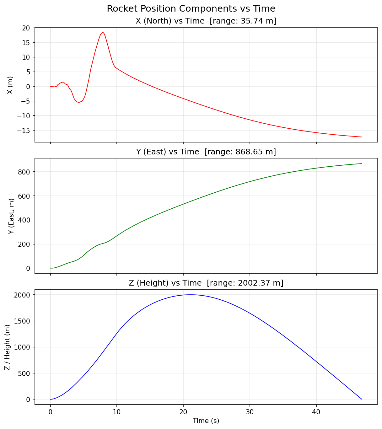
The result is written to a CSV and plotted — a full 3D trajectory, forces over time, and the commanded vs. actual gimbal angle history:
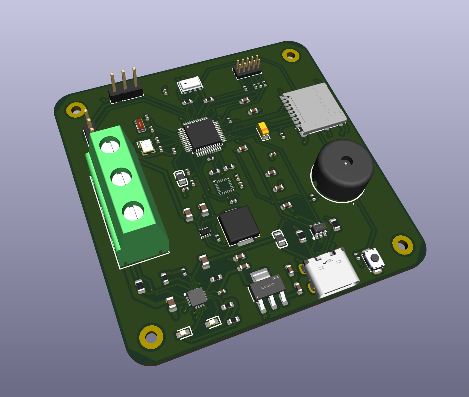
The eventual goal is for this to fly on real hardware, not just in
simulation. artifacts/ and kiCAD/ hold the in-progress flight-computer
PCB design. The feat/launcher branch extends the STM32F103C8T6 board,
which carries an MPU-9250 IMU and an MS5611 pressure sensor, with:
J5, Molex 104031-0811) for onboard flight-data
storage.LS1, PS1240P02CT3) for audible status and alerts.J1 and J4) for the gimbal servos, with a
dedicated TPS61033 boost regulator supplying the servo power rail.J2, 2×5),
exposing SWDIO, SWCLK, SWO, and reset for the STM32.J6 and J3), with a
BQ24074 charger and power-path controller for charging from a USB-C
adapter and supplying the board from the battery or external input.These are schematic and PCB additions; firmware support and bench/flight
validation remain separate work. GPS is modeled in the simulator but is
not fitted to this PCB revision. The KiCad project is
kiCAD/schmatic/schmatic.kicad_pro,
with the schematic and board layout beside it.
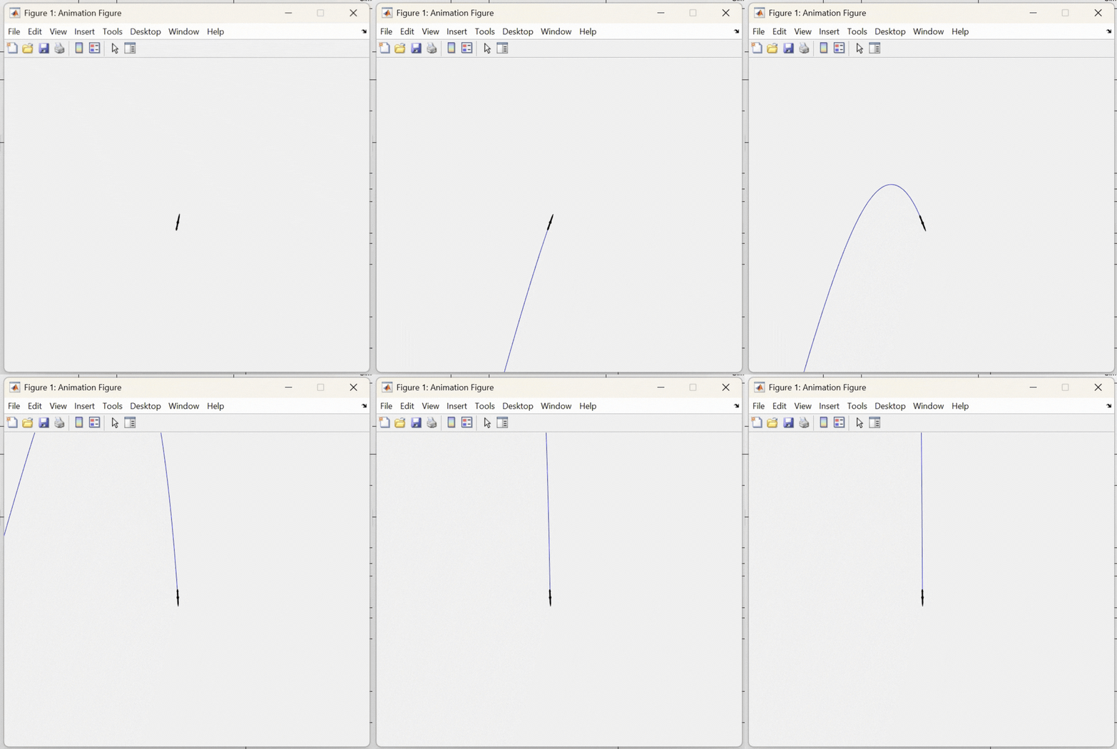
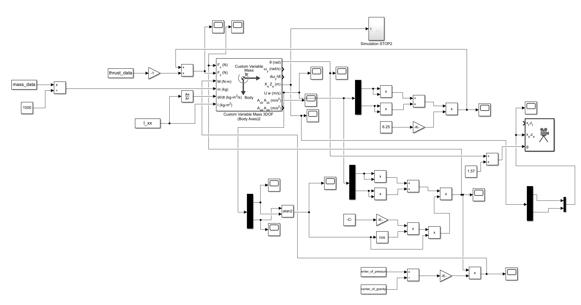
An earlier prototype of the trajectory math (before the C++ rewrite) was
built in MATLAB/Simulink — kept in sim/simulink/ and sim/matlab/ for history, but
superseded by sim/rocket_cpp/, which is now the actively developed
simulation:
The simulator is a standard CMake C++ project. From sim/rocket_cpp/:
cmake -S . -B build
cmake --build build
./build/rocket_cpp
This loads sim/data/rocket.ork, runs a full guided flight, and writes
rocket_trajectory.csv plus plots. See
sim/rocket_cpp/README.md for the full build
prerequisites and how to point it at a different .ork/target.
Every plotting script reads from that same rocket_trajectory.csv, so
they all stay in sync with whatever flight was simulated last:
| Script | What it shows | Run it |
|---|---|---|
scripts/plot_trajectory.py | The 7-subplot flight-analysis figure — called automatically at the end of every ./build/rocket_cpp run, not something you normally run by hand. | python3 scripts/plot_trajectory.py rocket_trajectory.csv rocket_analysis.png |
scripts/trajectory.py | The control panel, not just a viewer: an interactive, rotatable 3D flight path (mouse to orbit/zoom) with launch/burnout/apogee/impact/target markers and a pass/fail readout, plus text boxes for target x/y/z and initial tilt/yaw and a Run button that launches a fresh (fast --preview) simulation and redraws in place. Pass a CSV path instead to fall back to a plain one-shot viewer, no controls. | python3 scripts/trajectory.py |
scripts/tvc.py | The commanded gimbal angle over time, pitch and yaw axes on separate panels — what the nozzle actually did, lag included. | python3 scripts/tvc.py rocket_trajectory.csv |
scripts/x_force.py | The net world-frame X-force over time (thrust + drag; gravity has no X-component) — useful for seeing exactly when the motor burns out. | python3 scripts/x_force.py rocket_trajectory.csv |
scripts/make_axis_diagram.py | Regenerates the coordinate-frame/TVC reference diagram used above — a docs utility, not a per-flight plot. | python3 scripts/make_axis_diagram.py |
The active-guidance result is evaluated with a batch interception sweep, not just one hand-picked trajectory. The sweep samples static targets in the valid upper hemisphere of a 500 m sphere around the launch point, then records the rocket's minimum 3D distance to each target. Closest approach is linearly interpolated between simulation samples so the result is not tied to one discrete timestep.
The latest full-fidelity terminal-guidance sweep uses 16 radial shells and 96 directions per shell, producing 1,434 valid target cases:
| Metric | Result |
|---|---|
| Median miss distance | 6.185 m |
| Within 5 m | 606 / 1,434 |
| Within 10 m | 792 / 1,434 |
| Within 25 m | 980 / 1,434 |
| Worst miss distance | 144.068 m |
For comparison, the original waypoint/PID guidance had a 129.3 m median miss over the same target set. The remaining large misses are concentrated in far-lateral, very-low-altitude targets where the TVC reaches its 30° travel limit before the vehicle can build enough lateral velocity.
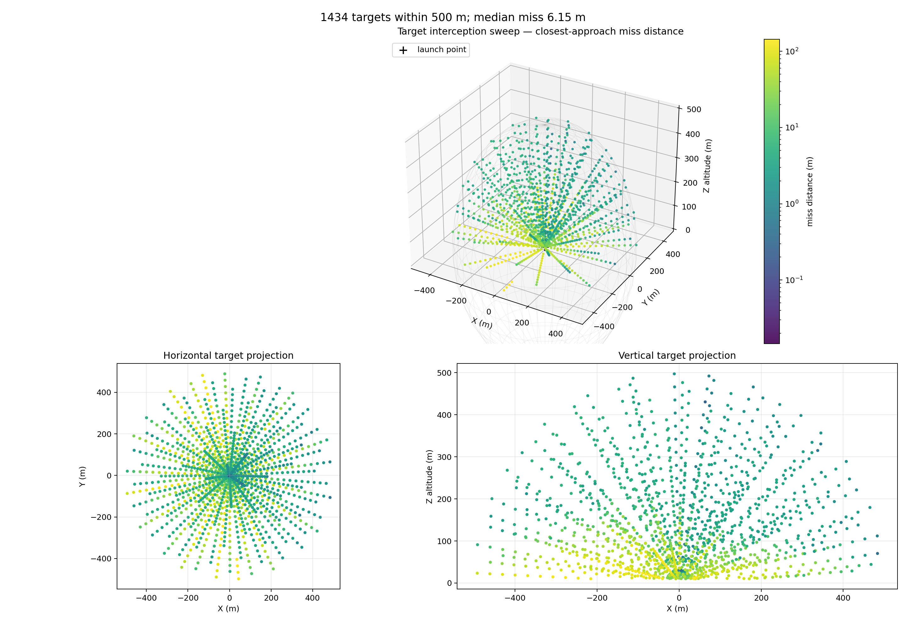
The data behind this figure is interception_results_terminal_dense_full.csv. To regenerate the plot after a new sweep:
cd sim/rocket_cpp
./build/interception_sweep --full --terminal \
  --output results/csv/interception_results_terminal_dense_full.csv
python3 scripts/plot_interception_sweep.pyThis is a staging-area project, not a finished flight-certified system. Worth knowing before trusting any number out of it:
sim/rocket_cpp/README.md's Staging Notes.
Structural, not a bug to be patched.Navigation now fuses that noisy GPS fix with the
accelerometer (an alpha-beta filter, gains derived from real sensor
numbers) instead of reading raw GPS — tested head-to-head, it makes the
guided trajectory ~10x more repeatable run to run, but doesn't improve
average accuracy, because no amount of filtering can reject a
persistent bias in the only absolute-position sensor available. That's
the same limitation every real GPS-only guided system has without a
second independent sensor backing it up — see sim/rocket_cpp/README.md's
Staging Notes for the full writeup.None of these are hidden — see
sim/rocket_cpp/README.md for the
full, current list, kept up to date as things change.
sim/rocket_cpp/README.md — the full
technical reference: every class and method, the exact math behind each
physics model, coordinate-frame conventions, build instructions, and a
running log of bugs found and fixed along the way.sim/rocket_cpp/docs/axis_and_tvc_reference.png
— the coordinate-frame and gimbal-geometry diagram referenced above.sim/rocket_cpp/include/{sim,ork,gnc}/ and
sim/rocket_cpp/src/{sim,ork,gnc}/. The thin executable wrapper lives in
sim/rocket_cpp/src/main.cpp; the single-flight orchestration and TVC test
sequence loader live in sim/rocket_cpp/src/simulation_runner.cpp with its
public declaration in sim/rocket_cpp/include/simulation_runner.hpp.Terms used throughout this document and the codebase, in plain language.
| Term | Meaning |
|---|---|
| Angle of attack (α) | The angle between where the nose points and the direction the vehicle is actually moving through the air, measured fore-aft. Zero when flying nose-first into the wind. |
| Apogee | The highest point of a flight — where vertical velocity crosses from positive (rising) to negative (falling). |
| Barrowman method | A set of formulas for predicting a rocket's aerodynamic coefficients (drag, stability, center of pressure) directly from its geometry, without wind-tunnel testing. |
| Body frame | A coordinate system attached to the rocket itself and rotating with it — "the rocket's own point of view," where its nose axis is always +Z regardless of which way the vehicle is actually pointed in the sky. |
| CG (center of gravity) | The single point where a body's mass balances — its "center of mass." |
| Closed-loop control | Continuously measuring a system's actual state and adjusting based on that measurement, as opposed to acting on a fixed, pre-planned schedule ("open-loop"). |
| CP (center of pressure) | The single point where the net effect of all aerodynamic forces on a body can be treated as acting. |
| Damping | A force or torque that resists motion in proportion to how fast that motion is already happening — what settles an oscillation down instead of letting it continue forever. |
| DCM (Direction Cosine Matrix) | A 3×3 rotation matrix used to convert a vector from one coordinate frame to another (e.g., body frame to world frame). |
| DOF (degrees of freedom) | How many independent ways a system can move. 3DOF = position in x/y/z only; 6DOF adds all three rotational axes (roll/pitch/yaw) too. |
| Dynamic pressure (q) | q = ½ρv² — a measure of how hard oncoming air pushes on a body, from air density (ρ) and airspeed (v). The basis for computing drag and other aerodynamic forces. |
| Euler angles | The standard roll/pitch/yaw representation of a rigid body's orientation — how far it's tipped, tilted, and turned from some reference orientation. |
| Euler integration | A numerical method for simulating motion: approximate what happens next using the current rate of change, over a small time step, repeated many times. |
| First-order lag | A system that eases toward a new target value exponentially over time rather than jumping there instantly — the standard model for how a real physical actuator (like a servo) responds to a new command. |
| Gimbal | A pivoting mount that lets something (here, a rocket engine's nozzle) tilt independently of the body it's attached to. |
| GNC (Guidance, Navigation, and Control) | The standard aerospace term for the combined sense-decide-act subsystem of a vehicle — in this project, the gnc/ module (sensors, Navigation, and ThrustVectorControl). |
| Integral windup | A failure mode of the "I" term in a PID controller: if error persists for a long time (e.g., an actuator pinned at its limit), the accumulated integral can grow very large and cause a big overshoot once the error finally starts shrinking. Usually prevented by clamping the accumulator. |
| ISA (International Standard Atmosphere) | A standard reference model relating altitude to air pressure, temperature, and density. |
| Moment of inertia | A body's resistance to being rotated — the rotational equivalent of mass. |
| Normal force | The aerodynamic force acting perpendicular to a body's own axis (as opposed to axial force/drag, which acts along it) — what actually turns a rocket, not what slows it down. |
| PID controller | A feedback-control law combining Proportional (react to current error), Integral (react to accumulated past error), and Derivative (react to how fast error is changing) terms — one of the most common control algorithms in engineering. |
| Sideslip (β) | The same idea as angle of attack, but measured left-right instead of fore-aft. |
| Stability margin / weathercocking | The natural tendency of a well-designed (finned) rocket to turn its nose back into the oncoming airflow on its own, the same way a weathervane points into the wind — the reason passive, unguided rockets can fly straight at all. |
| Torque (moment) | A rotational force — a twist applied around some pivot point, as opposed to a straight-line push. |
| TVC (Thrust Vector Control) | Steering a vehicle by tilting the direction of its engine thrust, rather than (or in addition to) aerodynamic surfaces like fins. |
| World frame | A coordinate system fixed to the ground/launch site — "the outside observer's point of view," as opposed to the body frame, which moves and rotates with the rocket. |
Rocket/
├── sim/                 all simulation-only code, models, data, and docs
│   ├── rocket_cpp/      active simulation engine (see its own README.md)
│   │   ├── include/{sim,ork,gnc}/ headers, one folder per module
│   │   ├── src/{sim,ork,gnc}/     implementation, mirrors include/
│   │   ├── scripts/               Python plotting and analysis
│   │   └── data/                  TVC test sequences
│   ├── data/            shared OpenRocket and motor inputs
│   ├── simulink/        early Simulink prototype
│   ├── matlab/          early MATLAB support files
│   └── docs/            generated simulator manuals
├── artifacts/            hardware renders and component references
├── kiCAD/                flight-computer PCB design source
└── README.md whole-project overview| Qty | Value | Footprint | References |
|---|---|---|---|
| 7 | 100nF | PCM_JLCPCB:C_0402 | C10, C13, C14, C16, C18, C22, C24 |
| 6 | 4.7uF | PCM_JLCPCB:C_0603 | C1, C2, C3, C4, C5, C9 |
| 4 | 1.1kΩ | PCM_JLCPCB:R_0603 | R16, R17, R20, R21 |
| 4 | 10kΩ | PCM_JLCPCB:R_0603 | R1, R2, R3, R7 |
| 4 | 10kΩ | PCM_JLCPCB:R_0402 | R6, R9, R10, R22 |
| 4 | 10uF | PCM_JLCPCB:C_0603 | C6, C15, C26, C27 |
| 4 | 22Ω | PCM_JLCPCB:R_0402 | R12, R13, R14, R15 |
| 4 | MountingHole | MountingHole:MountingHole_2.2mm_M2_Pad | H1, H2, H3, H4 |
| 3 | 10pF | PCM_JLCPCB:C_0402 | C11, C12, C25 |
| 2 | 1.5kΩ | PCM_JLCPCB:R_0402 | R8, R11 |
| 2 | 10uF | PCM_JLCPCB:C_0805 | C20, C21 |
| 2 | 15pF | PCM_JLCPCB:C_0402 | C7, C8 |
| 2 | 22uF | PCM_JLCPCB:C_0805 | C28, C29 |
| 2 | 5.1kΩ | PCM_JLCPCB:R_0805 | R4, R5 |
| 2 | Conn_01x03_Socket | Connector_PinHeader_2.54mm:PinHeader_1x03_P2.54mm_Vertical | J1, J4 |
| 2 | GZ2012D121TF | EasyEDA:L0805 | L1, L2 |
| 2 | LTST-C190KGKT | Flight_computer:LEDC1608X80N | LED1, LED2 |
| 1 | 104031-0811 | Flight_computer:1040310811 | J5 |
| 1 | 10nF | PCM_JLCPCB:C_0402 | C23 |
| 1 | 10uF | PCM_JLCPCB:C_CASE-A-3216-18(mm) | C19 |
| 1 | 1uF | PCM_JLCPCB:C_0402 | C17 |
| 1 | 49.9kΩ | PCM_JLCPCB:R_0402 | R19 |
| 1 | 750Ω | PCM_JLCPCB:R_0805 | R18 |
| 1 | AMS1117 | PCM_JLCPCB:SOT-223-3_L6.5-W3.4-P2.30-LS7.0-BR | U1 |
| 1 | BQ24074RGTT | Flight_computer:QFN50P300X300X100-17N-D | IC1 |
| 1 | Conn_02x05_Odd_Even | Connector_PinHeader_1.27mm:PinHeader_2x05_P1.27mm_Vertical | J2 |
| 1 | Connector, USB-TYPE-C-16P | PCM_JLCPCB:TYPE-C-SMD_HX-TYPE-C-16PIN | J3 |
| 1 | L | Inductor_SMD:L_APV_APH0620 | L3 |
| 1 | MPU-9250 | Sensor_Motion:InvenSense_QFN-24_3x3mm_P0.4mm | U4 |
| 1 | MS561101BA03-50 | EasyEDA:SENSORS-SMD_MS5611-01BA03 | U2 |
| 1 | PS1240P02CT3 | Flight_computer:PS1240P02BT | LS1 |
| 1 | Q13FC1350000400 | PCM_JLCPCB:FC-135R_L3.2-W1.5 | X2 |
| 1 | STM32F103C8T6 | PCM_JLCPCB:LQFP-48_7x7mm_P0.5mm | U6 |
| 1 | TB004-750-03GR | Flight_computer:TB004-750-03GR | J6 |
| 1 | TPS61033DRLR | Flight_computer:SOTFL50P160X60-8N | PS1 |
| 1 | Tactile Button, 160gf | PCM_JLCPCB:SW_TS-1088-AR02016 | S1 |
| 1 | USBLC6-4SC6 | EasyEDA:SOT-23-6_L2.9-W1.6-P0.95-LS2.8-BL | D1 |
| 1 | X322516MLB4SI | PCM_JLCPCB:OSC-SMD_4P-L3.2-W2.5-BL | X1 |
It measures 65 × 65.5 mm and has 2 copper layers, 1.6 mm thick.
77 parts, built around the STM32F103C8T6, MS561101BA03-50, AMS1117 and BQ24074RGTT. The full list of its parts is on this page, with links to each part's symbol and footprint where PCBKit's library has them.
From the Yorha-7/Rocket repository on GitHub, at the commit this page was made from: the board is kiCAD/schmatic/schmatic.kicad_pcb and its schematic kiCAD/schmatic/schmatic.kicad_sch. PCBKit opens the board in the browser, with nothing to install.
Its repository states no licence, so its author keeps all rights: ask Yorha-7 before reusing the design.

sensors-inl/Nervous-EDA
ECAD design files, firmware source code and standalone application for the EDA sensor of the Nervous project.

sensors-inl/Nervous-ECG
ECAD design files, firmware source code and standalone application for the ECG sensor of the Nervous project.

hghaken/ESP-iRadio
ESP32 internet radio with Bluetooth A2DP output (headphones/speaker), 1.69" display and web control


muccc/WomoLIN
Open Source Steuerung von LIN Bus Geräten im Caravan Bereich.