2 layers155.5 × 65.9 mm
Picozorro one th
maximevince/PicoZorro
Amiga Zorro-II Bus Cards using nothing but an RPi Pico to interact with the bus
48 parts2
 yesnoj/FilMachine_Reworked
FilMachine is an automated film processing machine designed for photographic film development. It handles the entire process: chemical baths, water rinses, temperature regulation, and motor-driven film agitation — all…
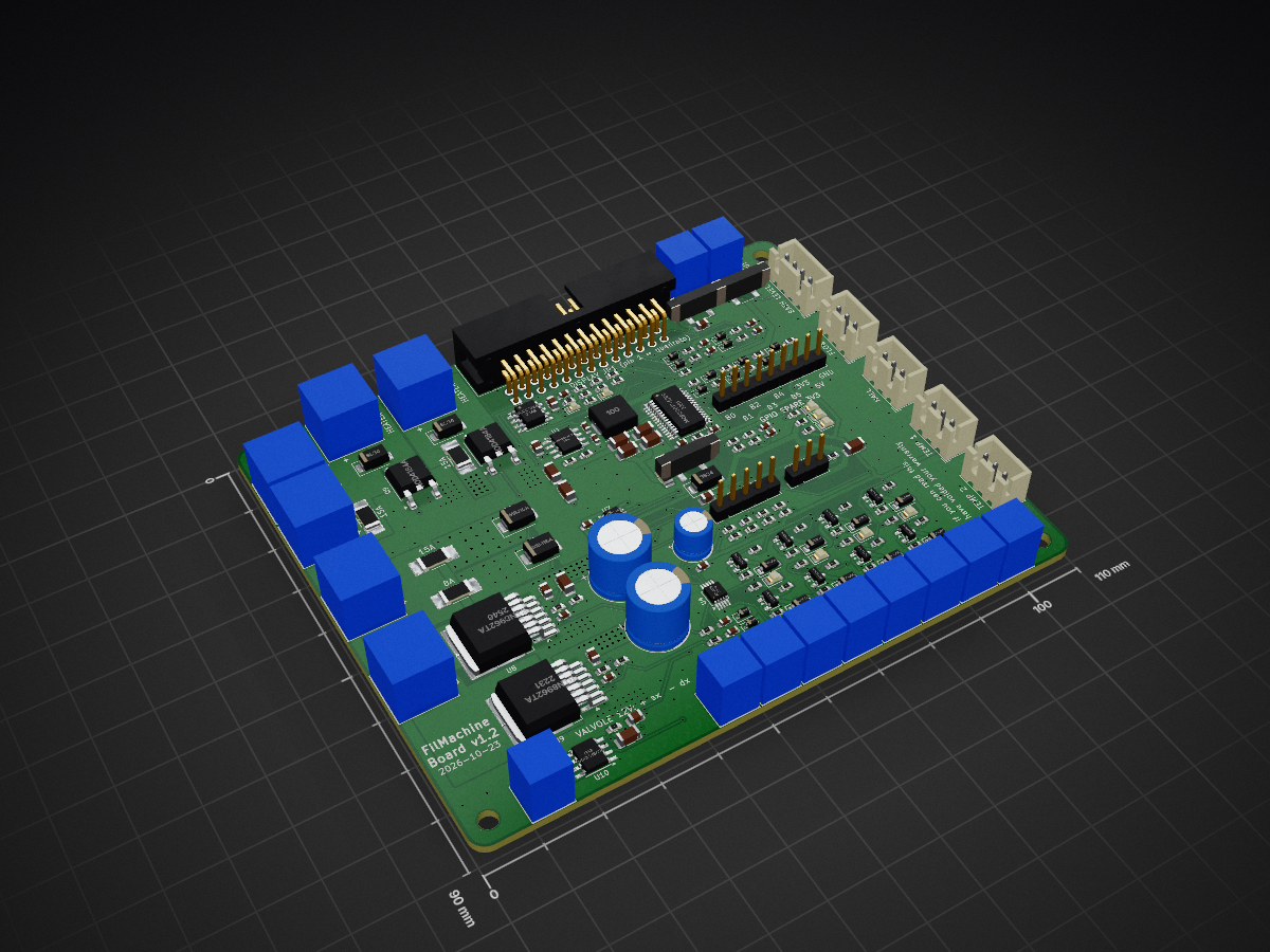
FilMachine Mainboard is an open-source printed circuit board by yesnoj, from the yesnoj/FilMachine_Reworked repository on GitHub. It is a 4-layer board of 110 × 90 mm with 205 parts on 118 nets, routed with 1,666 tracks and 575 vias.
It is built around the BTN8962TAAUMA1, ADS1115IDGSR and DRV8871DDARQ1, with the LMR33630ADDA, UCC27524DR and SN74LVC2G08DCTR among its other parts. Its parts include 71 resistors, 38 capacitors, 38 diodes, 26 connectors and 10 transistors. It belongs with the computers and single-board computers boards of this library.


FilMachine is an automated film processing machine designed for photographic film development. It handles the entire process: chemical baths, water rinses, temperature regulation, and motor-driven film agitation — all controlled through a 4.3" color touchscreen display.
The project includes a desktop simulator (SDL2 + LVGL) that reproduces the full touchscreen UI on macOS/Linux (a Windows build is produced by CI), enabling rapid development and testing without physical hardware, plus an automated test suite (19 suites). A Flutter companion app connects via WebSocket and provides full remote control from any mobile device on the same network.
The interface is bilingual (English / Italiano) — selectable from Settings, applied with an automatic reboot — and every boot writes a diagnostic log to the SD card (/log/boot_NNNN.txt), including the crash summary of the previous run when the firmware panicked.
The repository also holds the mechanical side of the project: the 3D-printed film reel auto-loader (bench prototype v1, for 135 and 120 film) — see Film Reel Auto-Loader.
FilMachine takes the guesswork out of developing photographic film at home or in a small lab. Instead of manually timing each step, pouring chemicals by hand, and constantly checking the thermometer, FilMachine automates everything. You load your film in the developing tank, select a process, and press Start. The machine takes care of the rest: filling the right chemical at the right time, keeping the temperature stable, rotating the film at the correct speed, rinsing between steps, and alerting you when the process is complete.
It supports both color negative (C41, E6) and black & white film development workflows, with full customization of every parameter.
The project has a dual-target build system that produces ESP32-P4 firmware or a native desktop application from the same codebase. The only supported hardware board is the Guition JC4880P433 (ESP32-P4).
| Layer | Firmware (ESP32-P4) | Simulator (macOS/Linux) |
|---|---|---|
| UI Library | LVGL 9.5.0 | LVGL 9.5.0 (identical) |
| Display | ST7701S 480×800 MIPI-DSI → landscape 800×480 via PPA | SDL2 window (800×480) |
| Touch Input | GT911 (physical 480×800 → remapped to 800×480) | SDL2 mouse events |
| Storage | FatFS on MicroSD (SDMMC 4-bit, ~40 MB/s) | POSIX file I/O (sd/ directory) |
| RTOS | FreeRTOS (ESP-IDF) | Stub (queues work, tasks are no-ops) |
| 2D Acceleration | PPA hardware engine (rotate, scale, blend, fill) | — |
| Audio | ES8311 codec via I2S + power amplifier | — |
| Temp Sensors | DS18B20 OneWire | Simulated (20°C ambient, heater model) |
| Motor/Pump | DBH-12V dual H-bridge (motor ch.A + pump ch.B) + MCP23017 solenoid driver | printf stubs |
| OTA Updates | esp_ota_ops + esp_http_server | Simulated (progress timer) |
| Build Tool | ESP-IDF (idf.py) | CMake + Make |
| Sensors | Flow meter, water level, hall effect | Simulated |
| Compiler | riscv32-esp-elf-gcc | Native cc/gcc/clang |
The simulator replaces all hardware-specific code with a stub layer that provides compatible implementations:
/FilMachine.json) to files inside an sd/ subdirectory of the directory the simulator is launched from, so read/write operations work transparently.The key architectural principle is that all UI code is shared 1:1 between firmware and simulator. Pages, elements, event handlers, and business logic are identical — only the hardware abstraction layer changes.
FilMachine_Reworked/
│
├── main/                          # Core source (shared with ESP32 firmware)
│   ├── include/
│   │   └── FilMachine.h           #   Main header — all structs, enums, constants, prototypes
│   ├── FilMachine.c               #   ESP32 entry point — board-conditional display/touch init
│   ├── accessories.c              #   Utilities — linked lists, deep copy, config I/O, keyboard
│   ├── lang.c                     #   EN/IT string table (generated by scripts/gen_lang.py)
│   ├── sd_log.c                   #   Boot/crash logger on SD (/log/boot_NNNN.txt, firmware only)
│   ├── mini_json.c                #   Dependency-free JSON parser for the config file
│   ├── ota_update.c               #   OTA firmware update (SD card + Wi-Fi web server)
│   ├── ws_server.c                #   WebSocket server for Flutter companion app
│   ├── film_loader.c              #   Film loading cycle (wind, stall detect, cut, tail) — Tools → Load film
│   └── ui_profile.c               #   Centralized UI layout constants (800×480)
│
├── c_pages/                       # UI pages (screens)
│   ├── page_splash.c              #   Splash screen — standard, random, and custom modes with
│   │                              #     10 palettes, 6 shape styles, 9 title fonts, PRNG engine
│   ├── page_menu.c                #   Tab bar navigation (Processes / Settings / Tools)
│   ├── page_processes.c           #   Process list with filtering
│   ├── page_processDetail.c       #   Process creation & editing
│   ├── page_stepDetail.c          #   Step creation & editing with validation
│   ├── page_settings.c            #   Machine settings, grouped in sections (process, rotation, liquids, display, system)
│ ├── page_tools.c # Maintenance tools, import/export, statistics, OTAmacOS:
brew install cmake sdl2 pkg-configUbuntu / Debian:
sudo apt install cmake libsdl2-dev pkg-config build-essentialLVGL v9.5.0 is automatically cloned from GitHub on the first build if not present (the firmware pulls the same version through the ESP-IDF component manager, lvgl/lvgl ~9.5.0).
Windows: there is no local recipe; the GitHub Actions workflow .github/workflows/windows-sim.yml builds filmachine_sim.exe with MSYS2/MinGW on every push to main that changes more than the documentation (or on demand from the Actions tab) and uploads it — with its runtime DLLs and a freshly generated sd/ config — as the filmachine-sim-windows artifact.
mkdir -p build800 && cd build800
cmake ..
make filmachine_sim
The simulator opens an 800×480 window matching the JC4880P433 physical panel in landscape orientation.
mkdir -p build800 && cd build800
cmake ..
make filmachine_test
./filmachine_testRequires the ESP-IDF toolchain (v5.5.x or later) installed and configured.
Important: run idf.py from the project root, not from build800/.
cd FilMachine_Reworked
. $HOME/esp/esp-idf-v5.5/export.sh     # Must be ESP-IDF 5.5.x or later

# First-time setup: set target to esp32p4 (creates sdkconfig from defaults)
idf.py set-target esp32p4

# Build — board is auto-detected from IDF_TARGET
idf.py build
The main/CMakeLists.txt automatically sets -DBOARD_JC4880P433. No manual -DCMAKE_C_FLAGS flag is needed (passing -D CMAKE_C_FLAGS="-DBOARD_JC4880P433" is harmless but redundant).
See
COMMANDS.mdfor the canonical quick reference: simulator + board build, flash/monitor, generating and copying the SD config, version bumping and cleanup.
The firmware binary is produced at build/FilMachine.bin. To flash it directly to a connected board:
idf.py flashOr use the all-in-one helper (written for macOS), which sets the target if needed, patches sdkconfig for the P4 board, increments the build number in version.txt, builds, looks for the serial port, flashes and opens the monitor:
./flash_p4.sh
flash.shandsetup.share leftovers of the earlier ESP32-S3 workflow (they copy sources between the oldFilMachine_Simulator_v2folder and theFilMachine_Peterepository). They are not used for the ESP32-P4 and can be ignored.
P4 note: the bootloader offset on ESP32-P4 is 0x2000 (different from ESP32-S3's 0x0). This is handled automatically by idf.py when the target is set correctly.
To check the firmware size (useful for verifying OTA partition fit):
idf.py sizeThe simulator includes a built-in UI inspection mode to speed up layout tuning.
gui.page.processes.newProcessButton)x, y)w, h)This is especially useful when adjusting coordinates inside ui_profile.c, because you can identify the exact widget and immediately see its current geometry in the simulator.
cd build800
./filmachine_sim
The simulator opens an 800×480 window that reproduces the exact touchscreen interface. Use the mouse to simulate touch input (click = tap, click-drag = swipe/scroll).
sd/FilMachine.json)sd/FilMachine_Backup.json)[SIM] sysAction: ...)To generate realistic film development recipes:
python3 scripts/genFilMachineCFG.py --realistic --output build800/sd/This creates config files with authentic C41, E6, and B&W development processes.
cd build800
./filmachine_test
Results are displayed in the terminal and saved to test_results/test_results_YYYYMMDD_HHMMSS.txt.
| Suite | Description |
|---|---|
| Navigation | Splash screen, menu display, tab switching |
| Processes | Process list rendering, creation UI |
| Process CRUD | Full create/read/update/delete lifecycle |
| Steps | Step creation, swipe gestures, deletion |
| Step CRUD | Step lifecycle with validation |
| Execution | Process checkup and execution flow |
| Persistence | Config save → reload → verify all fields, stats persistence, calibration offset |
| Settings | Settings UI, default values, slider/switch behavior, calibration, alarm |
| Filter | Filter by name, film type, preferred flag |
| Tools | Cleaning, draining, statistics display, timer pause/resume, alarm functions |
| Edge Cases | Boundary conditions, max limits, error recovery |
| Utilities | Helper functions, linked list operations, drain/fill overlap calculation |
| UI Profile & Sensors | Profile values match original, popup dimensions, font pointers, sensor stubs, board constants |
| OTA | OTA update UI, Wi-Fi popup PIN generation, progress popup |
| WebSocket | WebSocket command handling, async LVGL dispatch |
| New Settings | Extended settings validation |
| Self-check | Self-check diagnostic wizard phases |
| LiveSync | Live sync between WebSocket state and LVGL UI |
| Destroy & Lifecycle | Memory cleanup, object destruction |
| Film loader | Loading cycle 135/120, early stall / no spin / too long errors, Cut now, Stop, blade test, popup from the app |
| Maintenance from the app | Drain and Clean started, stopped and closed by WebSocket commands (popups on the display, state fields), only the selected containers cleaned, one tool at a time, no process while one runs, Export queued with its result in the state |
The persistence tests verify that every field (process name, temperature, tolerance, film type, preferred flag, step names, durations, types, sources, discard flags) survives a full save-and-reload cycle.
Repeatable runs. Every run starts from the same data: the runner generates three test processes with the default settings and rewrites sd/FilMachine.json in the run directory, so a run never depends on what the previous one saved (steps used to pile up on the first process until the 30-step limit made the step tests fail). FM_TEST_ONLY=<suite>,<suite> runs only some suites (names after test_suite_, e.g. FM_TEST_ONLY=navigation,tools).
Timers run on real time. The SDL display makes LVGL read the real clock, so test_pump() processes events but does not advance LVGL timers; tests that wait for a 1 s timer sleep (see pump_real() in test_maintenance_remote.c).
Memory. The simulator and the tests use the C-library malloc for LVGL, like the board. With LVGL's own 256 KB pool the heap fragmented after a few suites, an allocation failed and LVGL's malloc assert spun forever, which looked like random hangs in the step tests. To check memory errors, build the runner with -fsanitize=address: AddressSanitizer then sees LVGL's allocations too.
The simulator and firmware include a built-in WebSocket server (ws_server.c) that enables remote control from the Flutter companion app or any WebSocket client. The server starts automatically and listens on port 81 at path /ws.
All commands use JSON format: {"cmd":"command_name", ...params}.
| Command | Parameters | Description |
|---|---|---|
get_state | — | Returns full machine state (settings, runtime, temperatures, progress, alarms, maintenance fill, film loader, drain, clean and export status) |
get_processes | — | Returns complete process list with steps, indexed for remote referencing |
start_process | index | Start a process by list index; initializes checkup and begins execution |
checkup_advance | — | Advance to next checkup phase (Setup → Fill → Temp → Check → Processing) |
stop_now | — | Immediately halt the running process and drain |
stop_after | — | Stop after the current step completes |
close_process | — | Close a finished/stopped process and free checkup resources |
create_process | name, temp, tolerance, filmType, tempControlled, preferred | Create a new process |
edit_process | index, name, temp, tolerance, filmType, tempControlled, preferred | Edit an existing process |
delete_process | index | Delete a process |
add_step | processIndex, name, mins, secs, type, source, discard | Add a step to a process |
edit_step | processIndex, stepIndex, name, mins, secs, type, source, discard | Edit a step |
delete_step | processIndex, stepIndex | Delete a step |
reorder_step | processIndex, from, to | Move a step within a process |
set_setting | key, value | Update a machine setting (see key list below) |
reset_defaults | — | Restore all settings to factory defaults |
wifi_scan | — | Scan for Wi-Fi networks; results arrive via a wifi_scan_results event |
fill_start / fill_stop | target (0 = water bath, 1 = chemistry) | Maintenance fill (self-calibrates the fill time; refused with fill_rejected while a process runs) |
tune_test / tune_set / tune_cancel | kind (0 pump, 1 motor, 2 volume), percent, on | Live test, store or cancel a Tune value |
drain_start / drain_stop / drain_close | — | Drain machine: start (no confirm page, the app asks), Stop, Close after the end (alarm off, popup closed). Refused with drain_rejected while a process or another maintenance tool runs |
recover_start / recover_stop / recover_close | container (0 = C1, 1 = C2, 2 = C3) | Empty that chemistry into its recovery bottle (machine v7): wash the line, discard the head, transfer, wash again. Progress in recoverToolState (0 idle, 1 running, 2 stopping, 3 done, 4 stopped), recoverToolPhase (0..3), recoverToolPct, recoverToolRemaining, recoverToolMovedMl. Refused with recover_rejected while a process or another tool runs; a drain still finishing is waited for |
clean_start | mask (bit0 C1, bit1 C2, bit2 C3), cycles (1–5), drainWb | Clean machine with these choices (shown on the display popup). Refused with clean_rejected (processing, busy, no_container) |
clean_stop / clean_close | — | Clean: Stop (the container is pumped back first) / Close after the end |
export_config | — | Export configuration and processes to the backup file on the SD card; the result arrives as exportSeq / exportOk in the state |
load_start | format (0 = 135, 1 = 120) | Start loading the film onto the reel (refused with a load_rejected event while a process runs or a load is in progress) |
load_stop | — | Stop the loading (motor off, blade back to rest) |
load_cut | — | Cut now, without waiting for the reel to stop |
cutter_test | angle (0–180) | Hold the cutter servo at that angle for a few seconds (setup) |
cutter_cycle | — | One blade up/down cycle, motor off |
The cleanTool* state fields include cleanToolProcessArc, cleanToolCycleArc and cleanToolPumpArc: the values of the three arcs exactly as drawn on the display's Clean popup, so the app draws the same picture.
set_setting keys — tempUnit, waterInlet, tempCalibOffset, chemCalibOffset, filmRotationSpeed, rotationInterval, random, persistentAlarm, autostart, drainFillOverlap, multiRinseTime, lineRinseEnabled, lineRinseTime, tankSize, pumpSpeed, chemCalibFillSecs, wbCalibFillSecs, chemistryVolume, invertPump, brightness, volume, splashDefault, splashRandom, splashPalette, splashShapeStyle, splashComplexity, language (0=EN, 1=IT — applied at next boot), screenOffMins (5/10/30, 0=never), wifiEnabled, loadSpeed (reel motor % while loading), cutterRestUs / cutterCutUs (servo pulse in µs at rest and at the top of the cut). All of these are also included in the broadcast state JSON.
The server uses simple strstr() JSON parsing with no external library (no cJSON, no heap allocation for parsing). All commands that modify LVGL state are dispatched via lv_async_call() to ensure thread-safe UI updates. State changes are automatically broadcast to all connected clients.
The companion app is a Flutter application that provides full remote control of FilMachine from any mobile device or desktop on the same network. It lives in its own repository, FilMachine_App (private); see its README for detailed documentation.
Keeping the two in step. The app mirrors the protocol implemented in main/ws_server.c. Whenever a field is added to build_state_json() or a key to set_setting, the app needs the same addition in its MachineState model, in MachineService._readSetting and in its Settings screen. The app release synced with firmware v0.0.0.54 parses all 71 state fields and sends all 17 commands; the only set_setting keys it never sends are the fill calibrations (read-only in the app) and wifiEnabled.
_filmachine._tcp), plus manual IP/port entryThe app uses Provider for state management. A central MachineService (ChangeNotifier) maintains the WebSocket connection and holds the current MachineState — a data class with one field per key of the JSON state broadcast. All screens rebuild reactively when state changes.
This is where you manage your film development recipes. Each process is a sequence of steps the machine executes in order. The list shows each process with its name, total time, film type icon, and a star if marked as preferred.
Each process contains steps. A step represents one phase: "Developer", "Stop Bath", "Fixer", "Wash", etc.
For each step you configure: name, duration (minimum 30 seconds), chemical type (Chemistry / Rinse / Multi-Rinse), source container (C1, C2, C3, or WB), and whether to discard the chemical after use.
The three step types behave differently during execution: a Chemistry step fills once from a container and soaks for the whole step time (liquid recovered or discarded per the flag). A Rinse step fills once (from any source), soaks, and always discards to waste at the end. A Multi-Rinse step is not a single soak: the tank is repeatedly filled with fresh water (always from the water bath), agitated for one cycle — the "Multi-rinse cycle time" setting — then fully drained to waste, over and over until the step's total duration elapses. If the total time isn't an exact multiple of the cycle time, the last cycle runs longer so the step still ends exactly on time. This matches the Adeo dev.a behaviour and is ideal for final washes where the water must be changed frequently.
Open a process and tap Play. The machine walks through pre-flight checks, then executes each step automatically.
Pre-flight checks: tank size selection, water bath fill, tank presence verification, motor check, and temperature stabilization (for temperature-controlled processes).
During execution: the screen shows the current step name and remaining time, chemical source, current/target temperature, and upcoming steps.
Stopping: "Stop now!" halts immediately (potentially unsafe). "Stop after!" waits for the current step to finish — the safer choice.
The splash screen appears at boot and supports three modes, configured via Settings → Splash Screen:
Use Default — The built-in "Deep Ocean" splash: a hand-tuned composition with a teal-to-navy gradient, geometric shapes, and the "FILMACHINE" title in Montserrat 48. This is the factory default.
Random next boot — Each boot generates a completely new splash from scratch using a tick-derived seed. The PRNG (xorshift32) deterministically selects a palette, shape style, complexity, title position, and title font — producing a unique visual identity every time the machine starts.
Custom — Fine-tune the splash parameters manually: Palette (10 options), Shape Style (6 options), and Complexity (20–100 in steps of 20). The popup shows a live preview of the current configuration as the background behind its own controls, with a dark overlay for readability. Press the Random button to regenerate all parameters at once; if you like the result, it will be applied at next boot. The preview shows only the shape background (no title or play button) so you can evaluate the pattern clearly.
Title fonts — In Random and Custom modes, the title "FILMACHINE" is rendered with one of 9 fonts selected by the PRNG:
| Index | Font Name | Style |
|---|---|---|
| 0 | Montserrat 48 | Default sans-serif (same as Deep Ocean) |
| 1 | Air Americana | Bold italic display |
| 2 | Decaying Felt Pen | Hand-drawn brush effect |
| 3 | DS Digital | LED/LCD digital display |
| 4 | Evanescent | Ethereal and elegant |
| 5 | Nerdropol Lattice | Geometric/tech |
| 6 | Retrolight | Retro/vintage |
| 7 | Tropical Leaves | Decorative botanical |
| 8 | Wishful Melisande | Calligraphic script |
All fonts are converted from TTF/OTF to LVGL .c bitmap arrays using lv_font_conv with --no-compress --bpp 4 --range 0x20-0x7F (ASCII only, ~20–40KB each in flash).
Palettes — Cyberpunk, Aurora, Lava, Deep Ocean, Forest, Sunset, Machinery, Arctic, Neon, Pastel. Each defines a top/bottom gradient, 3 shape accent colors, and text/accent colors for the title.
Shape Styles — Overlapping Rects, Circles & Arcs, Mixed Shapes, Diagonal Bands, Grid Blocks, Radial Arcs.
The settings are grouped in sections, like the Tools tab; the whole page scrolls with its section titles. The app's Settings screen uses the same groups and the same wording.
| Section | Setting | Description | Range |
|---|---|---|---|
| Process | Process autostart | Auto-start when temperature reached | On/Off |
| Process | Persistent alarm | Alarm sounds until acknowledged | On/Off |
| Process | Temperature unit | °C or °F | — |
| Process | Temp sensor calibration | Calibrate against a reference thermometer. Short-press Tune to set ambient temp, long-press to reset. | Tune button |
| Film rotation | Rotation speed | Film agitation motor RPM | 10–100% |
| Film rotation | Inversion interval | Seconds between motor direction changes | 10–60s |
| Film rotation | Randomness | Random variation on inversion interval | 0–100% |
| Pump and liquids | Tank size | Default developing tank size | S (500ml) / M (700ml) / L (1000ml) |
| Pump and liquids | Chemistry volume | Amount of chemistry used per step | Low / High |
| Pump and liquids | Pump speed | Peristaltic pump speed (Kamoer KPHM600: 600 ml/min at 100 %); every fill/drain time is computed from it | 10–100% (default 100) |
| Pump and liquids | Invert pump | Invert H-bridge direction to compensate for pump physical switch position | On/Off |
| Pump and liquids | Water inlet | Automatic water fill if connected | On/Off |
| Pump and liquids | Drain/fill overlap | How much of fill/drain time counts as processing time (100% recommended) | 0–100% |
| Pump and liquids | Multi-rinse cycle time | Duration of each rinse in multi-rinse steps | 60–180s |
| Pump and liquids | Line rinse | Flush the shared pump line with water after each chemistry step | On/Off |
| Pump and liquids | Line rinse time | Duration of the line-rinse flush | 5–60s |
| Display and sound | Brightness | LCD backlight brightness (auto-dim after inactivity; board only) | 10–100% |
| Display and sound | Volume | Speaker volume | 0–100% |
| Display and sound | Screen off timeout | Minutes after the last touch before the screen turns off (dims in two steps first; disabled while a process runs) | 5 / 10 / 30 min / Never |
| Display and sound | Language | Interface language — the machine saves and reboots automatically to apply it | English / Italiano |
| System | Splash Screen | Opens a popup to configure the boot splash (see above) | Default / Random / Custom |
| System | Wi-Fi | Opens the Wi-Fi popup: scan, connect, status (used for OTA updates and the app) | — |
| System | Reset to Defaults | Restores every setting to its factory value | — |
The fill times are not settings any more: they are measured by the Maintenance fills in the Tools tab. The film loader's motor speed and cutter servo pulses (loadSpeed, cutterRestUs, cutterCutUs) are stored with the settings but are not shown on this page; they are set from the app's Load film screen (or in FilMachine.json).
All settings are saved automatically to the SD card when changed. Slider values are saved only when you release the slider (not during dragging) to reduce SD card wear.
recover_start)..bin file on the SD card. The system reads the firmware version from the binary header, asks for confirmation, then writes it to the secondary OTA partition. After completion, a reboot applies the new firmware. If the update fails, the bootloader automatically rolls back to the previous version.http://192.168.1.42) and a randomly generated 8-digit PIN for security. The user opens the URL in any browser on the same network and sees a drag-and-drop upload page styled with the FilMachine branding. After uploading the .bin firmware file, it is streamed directly to the OTA partition. The board reboots automatically when complete. Wi-Fi credentials (SSID/password) are configured in the Settings tab.The board supports two methods for over-the-air firmware updates. Both use the ESP-IDF dual-partition OTA mechanism: the new firmware is written to a secondary partition while the current one keeps running, and the bootloader swaps at reboot. If the new firmware fails to boot, automatic rollback restores the previous version.
idf.py buildbuild/FilMachine.bin to the SD card root, renamed as FilMachine_fw.binhttp://<board-ip> in a browser.bin file or click to select itThe .bin file is produced by idf.py build at build/FilMachine.bin. It contains an ESP32 application image with an esp_app_desc_t header that stores the firmware version, build date, and SHA-256 hash for integrity verification.
The project uses a custom partition table (partitions.csv) optimized for the 16MB flash chip. Each OTA slot is 6MB, giving ~59% free space with the current firmware size (~2.5MB, measured on a clean build of v0.0.0.54 with the repository defaults).
# Name      Type  SubType   Offset      Size
nvs         data  nvs       0x9000      24KB     NVS key-value storage
otadata     data  ota       0xF000       8KB     OTA boot flag (which slot to boot)
phy_init    data  phy       0x11000      4KB     Wi-Fi PHY calibration data
ota_0       app   ota_0     0x20000      6MB     Firmware slot A (active)
ota_1       app   ota_1     0x620000     6MB     Firmware slot B (updated via OTA)
coredump    data  coredump  0xC20000    64KB     Crash snapshot (read into the SD boot log)
(free)      —     —         0xC30000    ~4MB     Unallocated
Note: after adding the
coredumppartition, regenerate the sdkconfig once (rm sdkconfig && idf.py build) so theCONFIG_ESP_COREDUMP_*defaults are picked up, then flash normally (idf.py flashalso rewrites the partition table).
The bootloader alternates between ota_0 and ota_1: the new firmware is written to the inactive slot, and at reboot the bootloader swaps. If the new firmware crashes at startup, automatic rollback restores the previous working version.
The single source of truth is version.txt in the project root, in the form MAJOR.MINOR.PATCH.BUILD (e.g. 0.0.0.54). ESP-IDF uses it as the application version, so the value shown on the splash and in Tools → Software version is read at runtime from the running binary via esp_app_get_description()->version; the simulator gets the same string from CMakeLists.txt, which injects it as FW_VERSION_STR.
./flash_p4.sh increments the BUILD field before every build. To do it by hand:
./scripts/bump_version.sh          # 0.0.0.54 -> 0.0.0.55
./scripts/bump_version.sh --show   # print the current version without changing it
For a real release, edit version.txt directly (e.g. 0.1.0.0).
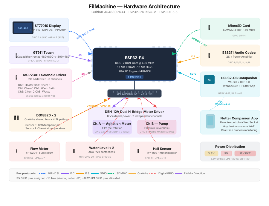
Guition JC4880P433 (-DBOARD_JC4880P433) — the only supported hardware board.
| Spec | Detail |
|---|---|
| MCU | ESP32-P4 (RISC-V dual-core @ 400 MHz) |
| Flash / PSRAM | 16 MB / 32 MB |
| Display | ST7701S 4.3" IPS, 480×800, MIPI-DSI (2-lane) |
| LVGL resolution | 800×480 (landscape, PPA-rotated) |
| Touch | GT911 capacitive (I2C) |
| SD card | SDMMC 4-bit (~40 MB/s) |
| Audio | ES8311 codec + power amplifier |
| 2D accelerator | PPA (rotate, scale, blend, fill) |
| Sensors | Flow meter, water-bath level (min/max), 6× chemical level (3 containers × min/max), Hall effect, 2× DS18B20, chip internal temp |
| Wi-Fi / BLE | ESP32-C6 companion chip over SDIO (ESP-Hosted) |
| ESP-IDF version | 5.5.x+ |
The JC4880P433's physical display is 480×800 in portrait orientation. FilMachine uses it in landscape mode at 800×480. The display pipeline works as follows:
Touch coordinates from the GT911 (which reports in 480×800 portrait) are inverse-mapped back to 800×480 LVGL coordinates. All of this is transparent to the UI code.
All external peripherals connect through the board's 2×13 Expand IO header (JP1):
| JP1 Pin | GPIO | Function |
|---|---|---|
| 1, 3 | — | VCC 3.3V output (2 pins) — (power) |
| 2, 4 | — | VCC 5V output (2 pins) — (power) |
| 5, 6, 16 | — | GND (3 pins) — (power) |
| 7 | 52 | Flow meter (YF-S201) — (used in code) |
| 8 | 33 | Motor IN1, H-bridge ch.A direction A — (used in code) |
| 9 | 51 | Pump ENA, LEDC PWM speed — (used in code) |
| 10 | 31 | Hall sensor (KY-003), reel turn counter for Load film — (used in code) |
| 11 | 50 | Pump IN2, H-bridge ch.B direction B — (used in code) |
| 12 | 30 | Water level max — (used in code) |
| 13 | 49 | Pump IN1, H-bridge ch.B direction A — (used in code) |
| 14 | 29 | Water level min (XKC-Y21) — (used in code) |
| 15 | 35 | DS18B20 OneWire, 2 sensors on shared bus — (used in code) |
| 17 | 34 | Motor IN2, H-bridge ch.A direction B — (used in code) |
| 18 | — | ESP_3V3 — (power, not used in code) |
| 19 | 32 | Motor ENA, LEDC PWM speed — (used in code) |
| 20 | — | C6_U0RXD (ESP32-C6) — (not used in code) |
| 21 | 28 | Cutter servo (MG90S), 50 Hz PWM — (used in code) |
| 22 | — | C6_U0TXD (ESP32-C6) — (not used in code) |
| 23 | 7 | I2C SDA, shared bus: touch + MCP23017 — (used in code) |
| 24 | — | C6_IO9 (ESP32-C6) — (not used in code) |
| 25 | 8 | I2C SCL, shared bus: touch + MCP23017 — (used in code) |
| 26 | — | C6_CHIP_PU (ESP32-C6) — (not used in code) |
All 12 P4 GPIO pins on JP1 are allocated — GPIO 28, the last spare, now drives the film loader's cutter servo.
hardware/FilMachine_Breakout_v1/ holds a KiCad project (schematic, PCB, the Python script that generates them, an HTML preview) and a BOM for a 70×50 mm two-layer breakout board. It plugs onto the Expand IO header (called J9 in its files) and brings the signals out to 5.08 mm screw terminals — motor, OneWire temperature, flow meter, I2C, water level, Hall sensor and power — plus a 1×8 header for the remaining GPIOs, and it carries the 4.7 kΩ pull-ups for I2C and OneWire. As its BOM.txt warns, check the header's power-pin mapping against the actual board with a multimeter before the first power-on.
| Component | Detail |
|---|---|
| Solenoid / IO expander | Adafruit I2C 8-Ch Solenoid Driver (#6318) — MCP23017 @ 0x20 on the shared I2C bus (GPIO 7/8). Port A drives the valves via on-board MOSFETs; Port B is broken out as raw GPIO and repurposed for level sensors + heater MOSFETs. |
| Motor Driver | DBH-12V dual DC motor driver — channel A: agitation motor, channel B: pump |
| Temperature | 2× DS18B20 OneWire sensors (water bath + chemical) on one bus (GPIO 35, 4.7 kΩ pull-up) |
| Pump | DC pump on DBH-12V ch.B — direction reversal for fill/drain (no pump valves) |
| Board power | USB Type-C 5 V (logic) + external 12 V rail for solenoids/motor/pump/heaters (common ground) |
MCP23017 pin map (I2C 0x20):
| Pin | Port | Function |
|---|---|---|
| 0 | A0 | Valve C1 |
| 1 | A1 | Valve C2 |
| 2 | A2 | Valve C3 |
| 3 | A3 | Valve WB (water bath) |
| 4 | A4 | Valve WASTE |
| 5 | A5 | Valve INLET (mains water into the bath, machine v6+) |
| 6 | A6 | Valve RECOVERY (seventh port of the collector, hose to the recovery bottle — Mainboard SPARE OUT 1, machine v7) |
| 7 | A7 | Bath circulator pump, 12 V (Mainboard SPARE OUT 2, machine v7) — on only while a process heats or develops |
| 8 | B0 | Chem C1 level MIN (XKC-Y21) |
| 9 | B1 | Chem C1 level MAX |
| 10 | B2 | Chem C2 level MIN |
| 11 | B3 | Chem C2 level MAX |
| 12 | B4 | Chem C3 level MIN |
| 13 | B5 | Chem C3 level MAX |
| 14 | B6 | Heater MOSFET 1 |
| 15 | B7 | Heater MOSFET 2 |
Port A pins sit behind the #6318 MOSFET drivers (valves). Port B pins are raw push-pull GPIO on the board's bottom edge: B0–B5 are inputs (pull-up, LOW = water present), B6–B7 are heater outputs (HIGH = on).
| Label | Purpose | Typical Use |
|---|---|---|
| C1 | Chemical container 1 | Developer |
| C2 | Chemical container 2 | Bleach / Stop bath |
| C3 | Chemical container 3 | Fixer |
| WB | Water bath | Rinse water (temperature-controlled) |
| WASTE | Waste drain | Discarded chemicals |
| Parameter | Limit |
|---|---|
| Max processes | 50 |
| Max steps per process | 30 |
| Process/step name length | 20 characters |
| Minimum step duration | 30 seconds |
Everything the firmware currently expects, for costing a build or a custom board. Quantities are for the standard 3-chemistry layout; prices are intentionally omitted (they move — estimate locally).
Two spreadsheets in the repository root complement this list (both in Italian): DistintaComponenti.xlsx, a parts list with specs, quantities, prices and links, and FilMachine_Custom_PCB_BOM.xlsx, the design worksheet for a future custom PCB (BOM, JP1 pin map, MCP23017 map, power budget). The MCP23017 map in that worksheet belongs to the custom-board design; the mapping the firmware uses today is the one in Peripheral Drivers.
Controller & storage
| # | Component | Qty | Role / notes |
|---|---|---|---|
| 1 | Guition JC4880P433 board | 1 | ESP32-P4 + 4.3" ST7701S 480×800 display + GT911 touch + ES8311 audio + SDMMC + ESP32-C6 (Wi-Fi/BLE). Main controller + UI. |
| 2 | microSD card | 1 | Config/process storage (FilMachine.json). Any small card. |
Actuation & power drivers
| # | Component | Qty | Role / notes |
|---|---|---|---|
| 3 | Adafruit #6318 I2C 8-ch solenoid driver (MCP23017 @0x20) | 1 | Port A → valves (MOSFET); Port B → level sensors + heater MOSFETs. |
| 4 | Solenoid valve, 12 V | 5 | C1, C2, C3, WB, WASTE. |
| 5 | DBH-12V dual DC motor driver (H-bridge) | 1 | Ch. A = agitation motor, ch. B = pump. |
| 6 | DC gear motor, 12 V | 1 | Tank agitation / rotation. |
| 7 | Kamoer KPHM600 peristaltic pump, 12 V (600 ml/min, PharMed tube 6.4 x 9.6) | 1 | Fill/drain by direction reversal; holds the liquid when stopped, pumps air to empty the line. |
| 8 | Heater MOSFET module | 2 | Driven from MCP Port B (B6/B7). |
| 9 | Heating element / immersion heater, 12 V | 1–2 | Water-bath heating (thermostat control). |
Sensors
| # | Component | Qty | Role / notes |
|---|---|---|---|
| 10 | DS18B20 waterproof probe (+ 4.7 kΩ pull-up) | 2 | Water bath + chemical temperature (one OneWire bus). |
| 11 | XKC-Y21 non-contact level sensor | 8 | WB min+max (2) + 3 chem containers × min/max (6). Need 5 V + signal pulled to 3.3 V. |
| 12 | Hall sensor (KY-003 / A3144) | 1 | Tank in-position / rotation; counts the reel turns while loading film. |
| 13 | YF-S201 flow meter | 1 | Water-bath inlet flow. |
Power & misc
| # | Component | Qty | Role / notes |
|---|---|---|---|
| 14 | 12 V PSU | 1 | Sized for valves + motor + pump + heaters (shared 12 V rail, common GND). |
| 15 | USB-C 5 V | 1 | Board logic power. |
| 16 | Resistors / level-shift, wiring, connectors | — | 4.7 kΩ (DS18B20), pull-ups for XKC-Y21, common ground. |
| 17 | Chemical containers + water bath + waste, tubing, enclosure | — | Mechanical build. |
Future / diagnostics-ready (optional)
| # | Component | Qty | Role / notes |
|---|---|---|---|
| 18 | Resistor dividers 12V/5V/3.3V → ADC1 | 3 | Enables live rail voltages in the diagnostics page (HAS_RAIL_MONITOR). |
| 19 | INA219 current sensor (I2C) | 1+ | Current draw per rail/load (not yet wired in firmware). |
Bench prototype v1 — files in 3D_Models/FilMachine_caricatore_v1/. The original notes, in Italian, are in that folder's README.
The loader winds the film onto the reel from the centre outwards, like the Rondinax: a motor turns the reel, a leader strip with a clip pulls the film out of the cassette, a guide arm bows it and lays it onto the ribs, and a cutter trims it when the winding is done. Formats: 135 and 120 on the same reel.

What it is and what it is not. It is an open test bench for validating the mechanics in daylight with scrap film. It is not yet light-tight or liquid-tight: that is the next phase, to be designed around mechanics that work.
Firmware status. This v1 bench (stepper + pendulum cutter) is not driven by the firmware. The firmware drives the loader built into the machine (v5): Tools → Load film (
main/film_loader.c) winds with the agitation motor, counts the reel turns with the Hall sensor, and cuts with a servo on GPIO 28 — see The Tools Tab. The sequence in Planned firmware sequence is kept as the reference for the bench.
| Folder | What's inside |
|---|---|
step/ | 21 parts as STEP, already in print orientation, plus the assemblies ASSIEME_135.step and ASSIEME_120.step |
stl/ | the same 21 parts as STL |
png/ | previews and section views |
src/ | parametric model (Python + CadQuery): python3 build_all.py regenerates everything |
verifiche.txt | outcome of the geometric checks from the last generation |
Each assembly contains 23 named, coloured bodies: the 19 parts used for that format plus the REF_ reference shapes (NEMA17 motor, servo, blade, 135 cassette or 120 spool). In Shapr3D every body can be hidden. All part faces are planes, cylinders and cones, so they can be edited directly.


Left: the adjustable reel, exploded (flanges, bayonet tube with the drum). Right: the pendulum cutter at three positions of its sweep.
PETG, 0.4 mm nozzle. No supports: every part is already oriented.
| Parts | Notes |
|---|---|
| 01, 02 flanges | 0.12–0.16 mm layers; the ribs bridge across the windows (6 mm) |
| 03 tube | upright; the bayonet V-grooves are at 45°, 0.12–0.16 mm layers |
| 05, 06 guide arms | upside down (roof on the bed); 0.6 mm walls at the tip: enable thin walls / Arachne |
| 09 bridge | standing on its short side, with a brim |
| 20 clip jaw | on its side, 0.12 mm layers; it is the finest part |
| all the others | 0.2 mm layers, 3 perimeters, 15–20 % infill |
Fit clearance used everywhere: 0.15 mm (FIT in src/common.py). If your printer prints tight or loose, change that value and regenerate.
The holes marked "self-tapping" are Ø2.6: the M3 screw cuts its own thread in the PETG.
135 — Cassette in the cradle with the lips up, towards the bridge; leader trimmed square. Arm raised. Bring the clip to the cassette, passing under the arm and through the central passage of the bridge, clip it onto the film (1 cm sticking out is enough), lower the arm. Start: the motor winds, stops at the end of the film, the blade cuts, and the motor takes up the tail.
120 — Flanges in the 120 position, arm 06, cradle 14. Roll in the cradle; unroll the backing paper until the film appears, then clip onto the film. While the motor winds, guide the paper up and back (as on the Rondinax 60). When the adhesive tape arrives: stop, advance 20 mm, cut.
Reel turns: 0.83 of leader strip, then 8.2 turns for a 36-exposure 135 (5.9 for 24 exposures) and 4.6 turns for a 120. Length wound after θ radians: L = 23·θ + 0.175·θ² mm.
Motor current, stall threshold and servo pulse widths have to be tuned on the bench: they have not been measured.
See verifiche.txt for the full output.
These are not guaranteed by CAD alone.
RIB_H, TIP_CLEAR, WALL_TIP, H_EDGE.All dimensions are in src/common.py. After a change, run cd src && python3 build_all.py (needs pip install cadquery): it re-exports parts and assemblies and re-runs all the checks.
A hidden factory/bring-up screen for validating hardware (especially a custom board).
How to open:
Live monitor (grouped panels, refresh ~3×/s): bath/chem temperatures, water-bath level (min/max), 3× chemical level (min/max), Hall magnet, flow (L/min + pulses), MCP23017 / SD / Wi-Fi status, and a System panel with ESP32-P4 internal chip temperature, free PSRAM, last reset reason, and uptime. A Power rails panel shows 12V/5V/3.3V (n/a until dividers + HAS_RAIL_MONITOR are provided).
Output controls (to test the board): toggle each valve (C1/C2/C3/WB/Waste/Rec — the recovery outlet on A6), run pump FW/RV/Stop, motor FW/RV/Stop, toggle heaters H1/H2 and the bath circulator (Circ, A7), play an audio test tone. Close turns every output off and returns to the splash.
Compile-time flags (in main/include/FilMachine.h and the board header) that change behaviour without touching logic:
| Flag | Default | Effect |
|---|---|---|
ENABLE_BOOT_ERRORS | 0 | 1 → show a blocking SD/I2C error screen at boot (tap to reboot). At 0 the errors are still detected + logged. |
VALVE_SELFTEST_ON_BOOT | 1 | Cycle the valves once at boot (runs in the background so the display isn't delayed). |
HAS_DUAL_HEATER | 1 | Two heater MOSFETs on MCP B6/B7 (vs a single Port-A relay). |
HAS_CHEM_LEVEL_SENSORS | 1 | 6 chemical-level sensors on MCP Port B (B0–B5). |
HAS_RAIL_MONITOR | 0 | 1 → read 12V/5V/3.3V rails via ADC in the diagnostics page (needs dividers + channel/ratio defines). |
MOTOR_MIN_ANALOG_VAL / PUMP_MIN_ANALOG_VAL | 90 / 64 | Lowest duty applied (motor: at the 10% slider position; pump: floor of the linear 0..250 mapping) — raise if the motor/pump stalls at low speed. |
PUMP_FLOW_ML_MIN (board header) | 600 | Flow of the pump at 100 %: fill/drain times of the process and of the Tools are computed from it (ml / flow). |
PUMP_PURGE_SECS | 4 | Seconds of air pumped after every drain (at 100 %, scaled with the speed): the tank is empty, so the liquid still in the line is pushed to where the drain went and the next fill starts with a dry line. |
XFER_CYCLE_ML | 300 | Volume of one tank cycle when the Tools move liquid between two collector ports (the tank is the measuring cup; it overflows at ~500 ml). |
CHEM_CONTAINER_ML / BATH_VOLUME_ML | 1000 / 12800 | Nominal volumes for the Tools' time estimates until a measured fill time exists. |
All data is stored on the SD card as a single JSON file, FilMachine.json (the old binary .cfg was replaced — JSON is human-readable, hand-editable and version-tolerant). Parsing/serialisation uses a small dependency-free parser (main/mini_json.c) that builds on both the board and the simulator (no cJSON). Writes are crash-safe (.tmp + atomic rename).
Schema:
{
  "settingsParams": {
    "tempUnit": 0, "waterInlet": 1,
    "filmRotationSpeedSetpoint": 50, "rotationIntervalSetpoint": 10, "randomSetpoint": 20,
    "isPersistentAlarm": 1, "isProcessAutostart": 0, "drainFillOverlapSetpoint": 100,
    "multiRinseTime": 60, "lineRinseEnabled": 0, "lineRinseTime": 10,
    "tankSize": 2, "pumpSpeed": 100,
    "chemCalibFillSecs": 0, "wbCalibFillSecs": 0, "chemistryVolume": 2,
    "tempCalibOffset": 0, "chemCalibOffset": 0,
    "splashRandom": 0, "splashPalette": 3, "splashShapeStyle": 0,
    "splashComplexity": 40, "splashSeed": 0, "splashDefault": 1,
    "wifiEnabled": 0, "wifiSSID": "", "wifiPassword": "",
    "brightness": 100, "volume": 60, "invertPump": 0,
    "language": 0, "screenOffMins": 10
  },
  "processes": [
    { "name": "C41 Color Std", "temp": 38, "tempTolerance": 0.3,
      "isTempControlled": 1, "isPreferred": 1, "filmType": 1,
      "timeMins": 23, "timeSecs": 15,
      "steps": [
        { "stepNameString": "Developer", "timeMins": 3, "timeSecs": 15,
          "type": 0, "source": 0, "discardAfterProc": 0 }
      ] }
  ],
  "machineStats": { "completed": 0, "totalMins": 0, "totalSecs": 0, "stopped": 0, "clean": 0 }
}
Notes on a few fields: tempCalibOffset/chemCalibOffset are in tenths of a degree (int16, clamped ±30 °C); chemCalibFillSecs/wbCalibFillSecs are the measured MIN→MAX fill times in seconds (0 = uncalibrated, capacity used as fallback); step type 0=Chemistry/1=Rinse/2=MultiRinse; step source 0=C1,1=C2,2=C3,3=WB. lineRinseEnabled (0/1) turns on a line rinse after each chemistry step: after draining a chemistry step, the shared pump line is flushed with clean water from the water bath, discarded to waste, for lineRinseTime seconds (5–60 s) before the next liquid is drawn — clearing chemistry residue from the common tubing to avoid cross-contamination. Opt-in (default off); uses extra water, so watch the bath level when the water inlet isn't connected.
Auto-save triggers: creating/editing/deleting a process, changing any setting, toggling preferred, duplicating processes or steps, and recording a fill calibration.
Export writes a backup copy (FilMachine_Backup.json); Import restores from it and reboots. Generate a fresh SD file with scripts/genFilMachineCFG.py --realistic --output sd/ (see COMMANDS.md).
In the simulator these files live in an sd/ subdirectory of the directory the simulator is launched from (e.g. sd/FilMachine.json); the folder is created on first run if missing.
The UI is fully bilingual: English (default) and Italiano. The language is selected in Settings → Language via a roller; on confirmation the machine saves the config and reboots automatically to rebuild the UI in the new language (the on-device UI is built once at boot).
Implementation: all ~350 UI strings live in a runtime lookup table (main/lang.c + main/include/lang.h) resolved through tr(). The xxx_text macros in FilMachine.h are untouched at call sites — they now expand to tr(STR_xxx). The table is generated/maintained by scripts/gen_lang.py, which holds the Italian dictionary; translations use ASCII apostrophes (Velocita') because the LVGL fonts are converted with --range 0x20-0x7F. The setting is persisted as "language" (0=EN, 1=IT) in FilMachine.json, exposed over WebSocket (set_setting, applied at next boot), and included in genFilMachineCFG.py.
To add or fix translations, edit the IT dict in scripts/gen_lang.py and mirror the change in main/lang.c (or regenerate). Adding a third language means extending lang_pair_t and the languageList roller options.
Every boot the firmware creates /log/boot_NNNN.txt on the SD card (the 20 most recent files are kept, older ones are pruned automatically). The file starts with a header — firmware version, build date, reset reason — and then captures in background all ESP_LOGx and LV_LOG lines (RAM-buffered, flushed to the card every 2 s so the UI is never blocked).
If the previous run crashed (panic or watchdog), the header also contains a PREVIOUS RUN CRASHED block with the offending task and program counter, read back from the core dump that the ESP32 saves to the dedicated 64KB coredump flash partition at panic time. The full dump stays in flash and can be decoded with idf.py coredump-info. This is the "black box": if the machine reboots on its own while no serial console is attached, pull the SD card and read the latest boot_NNNN.txt.
Not captured by design: bootloader output, the very first lines before the SD is mounted, raw printf calls, and the last ≲2 s before a hard crash (covered by the core dump summary instead). Module: main/sd_log.c (firmware only; the simulator links weak no-op stubs).
A standard C41 process: Pre-wash with water (1:00), Developer from C1 (3:15), Bleach from C2 (6:30), Wash (3:00), Fixer from C3 (6:30), Final Wash (3:00). Temperature control is critical — the machine maintains 38°C ± 0.3°C throughout.
B&W processes are more flexible: Developer from C1 (8:00), Stop Bath from C2 (1:00), Fixer from C3 (5:00), Wash (5:00). Temperature control can be disabled for ambient-temperature development, or set to 20°C ± 0.5°C for consistency.
E6 requires precise timing and temperature: First Developer (6:00), Wash (2:00), Color Developer (6:00), Wash (2:00), Bleach (6:00), Fixer (4:00), Final Wash (4:00). All at 38°C with tight ±0.3°C tolerance.
# ── Simulator (macOS/Linux) ──────────────────────────────
mkdir -p build800 && cd build800
cmake ..                                   # Configure (first time only)
make -j$(sysctl -n hw.ncpu) filmachine_sim # Build simulator (parallel)
./filmachine_sim                           # Run simulator (800×480 window)

# ── Tests ────────────────────────────────────────────────
make -j$(sysctl -n hw.ncpu) filmachine_test  # Build tests (parallel)
./filmachine_test                            # Run all 19 test suites

# ── Firmware (ESP32-P4) ──────────────────────────────────
cd ~/Documents/GitHub/FilMachine_Reworked       # Must be in project root!
. $HOME/esp/esp-idf-v5.5/export.sh        # Load ESP-IDF environment
idf.py set-target esp32p4                  # First time: set RISC-V target
idf.py build                               # Build firmware
idf.py flash monitor                       # Flash + open serial monitor
idf.py flash                               # Flash only (no monitor)
idf.py monitor                             # Serial monitor only (Ctrl+] to exit)
idf.py size # Show firmware size breakdown# Simulator: just run make again (incremental, from build800/)
cd build800 && make -j$(sysctl -n hw.ncpu) filmachine_sim
# If you added new .c files to CMakeLists.txt, re-run cmake first:
cd build800 && cmake .. && make -j$(sysctl -n hw.ncpu) filmachine_sim
# Build + run tests in one shot:
cd build800 && cmake .. && make -j$(sysctl -n hw.ncpu) filmachine_test && ./filmachine_test
# Firmware: idf.py handles incremental builds automatically
idf.py build
# Flash immediately after build:
idf.py build && idf.py flash monitor# Simulator: wipe build directory and reconfigure
rm -rf build800 && mkdir build800 && cd build800 && cmake ..
make -j$(sysctl -n hw.ncpu) filmachine_sim
# Firmware: full clean (also needed if sdkconfig changes)
idf.py fullclean
idf.py buildidf.py build
# The .bin file is at: build/FilMachine.bin
# For SD card update, rename and copy:
cp build/FilMachine.bin /Volumes/SDCARD/FilMachine_fw.binpython3 scripts/genFilMachineCFG.py --realistic --output build800/sd/# "CMakeLists.txt not found" when running idf.py
# → You're in the wrong directory. Run from the project root, not build800/
# Simulator won't compile after adding a new .c file
# → Re-run cmake: cd build800 && cmake ..
# LVGL not found
# → CMake clones it on the first configure. To do it by hand, from the project root:
# git clone --depth 1 --branch v9.5.0 https://github.com/lvgl/lvgl.git
# Serial monitor garbled output
# → Check baud rate: idf.py monitor -b 115200
# ESP-IDF not found / idf.py command not found
# → Source the environment: . $HOME/esp/esp-idf-v5.5/export.sh
# CMake: 'The "path" field in the manifest file ".../components/espressif__esp_lcd_touch/idf_component.yml"
# does not point to a directory'
# → dependencies.lock stores the absolute path of that local component on the machine that
# generated it. After moving or renaming the project folder (or on another computer), edit the
# "path:" under espressif/esp_lcd_touch in dependencies.lock to the new location. Deleting the
# lock file makes the component manager regenerate it, but with newer versions of the unpinned
# dependencies (mdns, esp_lcd_touch_gt911 and two transitive ones), which are untested here.
Private project. All rights reserved.
PeterB — Hardware design & firmware FrankP — Software development & testing
| Qty | Value | Footprint | References |
|---|---|---|---|
| 19 | 100k | Resistor_SMD:R_0603_1608Metric | R1, R41, R42, R43, R44, R45, R46, R47, R48, R61, R62, R70, R71, R72, R73, R74 +3 |
| 16 | 4.7k | Resistor_SMD:R_0603_1608Metric | R3, R6, R7, R16, R51, R52, R53, R54, R55, R56, R57, R58, R67, R68, R80, R82 |
| 12 | 1N5819WS | Diode_SMD:D_SOD-323 | D6, D7, D10, D11, D12, D13, D47, D48, D49, D50, D51, D52 |
| 11 | 100nF | Capacitor_SMD:C_0603_1608Metric | C5, C13, C14, C15, C16, C17, C18, C19, C41, C50, C51 |
| 10 | 10k | Resistor_SMD:R_0603_1608Metric | R8, R12, R13, R14, R20, R21, R22, R23, R64, R66 |
| 9 | 1k | Resistor_SMD:R_0603_1608Metric | R4, R5, R84, R97, R98, R99, R100, R101, R102 |
| 8 | 100R | Resistor_SMD:R_0603_1608Metric | R31, R32, R33, R34, R35, R36, R37, R38 |
| 8 | AO3400A | Package_TO_SOT_SMD:SOT-23 | Q1, Q2, Q3, Q4, Q5, Q6, Q7, Q8 |
| 8 | B5819W | Diode_SMD:D_SOD-123 | D21, D22, D23, D24, D25, D26, D27, D28 |
| 8 | Yellow | LED_SMD:LED_0805_2012Metric | D31, D32, D33, D34, D35, D36, D37, D38 |
| 6 | 1nF | Capacitor_SMD:C_0603_1608Metric | C20, C21, C22, C23, C54, C61 |
| 5 | 22uF 25V | Capacitor_SMD:C_1206_3216Metric | C7, C8, C9, C10, C59 |
| 4 | M3 | MountingHole:MountingHole_3.2mm_M3 | H1, H2, H3, H4 |
| 3 | 100nF 50V | Capacitor_SMD:C_0805_2012Metric | C52, C53, C58 |
| 3 | 10uF 25V | Capacitor_SMD:C_0805_2012Metric | C62, C63, C64 |
| 3 | 10uF 50V | Capacitor_SMD:C_1206_3216Metric | C2, C3, C57 |
| 3 | 15A | FM:FUSE_2410_SMD | F1, F2, F3 |
| 3 | Green | LED_SMD:LED_0805_2012Metric | D3, D4, D5 |
| 3 | SS34 | Diode_SMD:D_SMA | D8, D41, D42 |
| 2 | 1.1A | Fuse:Fuse_1812_4532Metric | F5, F7 |
| 2 | 1.5k | Resistor_SMD:R_0603_1608Metric | R85, R88 |
| 2 | 10R | Resistor_SMD:R_0603_1608Metric | R63, R65 |
| 2 | 470uF 25V | Capacitor_THT:CP_Radial_D10.0mm_P5.00mm | C55, C56 |
| 2 | 74LVC2G08 | Package_SO:SSOP-8_2.95x2.8mm_P0.65mm | U6, U7 |
| 2 | AOD4184A | Package_TO_SOT_SMD:TO-252-2 | Q9, Q10 |
| 2 | BTN8962TA | Package_TO_SOT_SMD:TO-263-7_TabPin8 | U8, U9 |
| 2 | Red | LED_SMD:LED_0603_1608Metric | D43, D44 |
| 2 | SMBJ16A | Diode_SMD:D_SMB | D1, D2 |
| 1 | 0.5A | Fuse:Fuse_1206_3216Metric | F6 |
| 1 | 100uF 35V | Capacitor_THT:CP_Radial_D6.3mm_P2.50mm | C1 |
| 1 | 10uH | FM:L_SLO0630H | L1 |
| 1 | 12V IN HEATER 1 | FM:TB_WJ500V-5.08-2P | J1 |
| 1 | 12V IN HEATER 2 | FM:TB_WJ500V-5.08-2P | J2 |
| 1 | 12V IN MAIN | FM:TB_WJ500V-5.08-2P | J3 |
| 1 | 12V OUT | FM:TB_DB301V-3.5-2P | J28 |
| 1 | 15k | Resistor_SMD:R_0603_1608Metric | R10 |
| 1 | 1uF 50V | Capacitor_SMD:C_0603_1608Metric | C6 |
| 1 | 1uF 50V | Capacitor_SMD:C_0805_2012Metric | C40 |
| 1 | 20k | Resistor_SMD:R_0603_1608Metric | R11 |
| 1 | 220R | Resistor_SMD:R_0603_1608Metric | R87 |
| 1 | 220nF 50V | Capacitor_SMD:C_0805_2012Metric | C4 |
| 1 | 24k | Resistor_SMD:R_0603_1608Metric | R2 |
| 1 | 2A | Fuse:Fuse_1812_4532Metric | F8 |
| 1 | 30k | Resistor_SMD:R_0603_1608Metric | R86 |
| 1 | 47uF 10V | Capacitor_SMD:C_1206_3216Metric | C60 |
| 1 | 5V OUT | FM:TB_DB301V-3.5-2P | J29 |
| 1 | 8A | FM:FUSE_2410_SMD | F4 |
| 1 | ADS1115 | Package_SO:VSSOP-10_3x3mm_P0.5mm | U4 |
| 1 | BATH LEVEL | Connector_JST:JST_XH_B4B-XH-A_1x04_P2.50mm_Vertical | J7 |
| 1 | C6 UART | Connector_PinHeader_2.54mm:PinHeader_1x05_P2.54mm_Vertical | J6 |
| 1 | DISPLAY JP1 | Connector_IDC:IDC-Header_2x13_P2.54mm_Horizontal | J5 |
| 1 | DRV8871DDA | Package_SO:TI_SO-PowerPAD-8_ThermalVias | U10 |
| 1 | FLOW | Connector_JST:JST_XH_B3B-XH-A_1x03_P2.50mm_Vertical | J11 |
| 1 | GPIO SPARE | Connector_PinHeader_2.54mm:PinHeader_1x09_P2.54mm_Vertical | J30 |
| 1 | HALL | Connector_JST:JST_XH_B3B-XH-A_1x03_P2.50mm_Vertical | J12 |
| 1 | HEATER 1 | FM:TB_WJ500V-5.08-2P | J23 |
| 1 | HEATER 2 | FM:TB_WJ500V-5.08-2P | J24 |
| 1 | LMR33630ADDA | Package_SO:TI_SO-PowerPAD-8_ThermalVias | U1 |
| 1 | MCP23017-E/SS | Package_SO:SSOP-28_5.3x10.2mm_P0.65mm | U3 |
| 1 | MOTOR | FM:TB_DB301V-3.5-2P | J26 |
| 1 | PUMP | FM:TB_WJ500V-5.08-2P | J25 |
| 1 | SERVO | Connector_PinHeader_2.54mm:PinHeader_1x03_P2.54mm_Vertical | J27 |
| 1 | SPARE OUT 1 | FM:TB_DB301V-3.5-2P | J21 |
| 1 | SPARE OUT 2 | FM:TB_DB301V-3.5-2P | J22 |
| 1 | TEMP 1 | Connector_JST:JST_XH_B3B-XH-A_1x03_P2.50mm_Vertical | J13 |
| 1 | TEMP 2 | Connector_JST:JST_XH_B3B-XH-A_1x03_P2.50mm_Vertical | J14 |
| 1 | UCC27524D | Package_SO:SOIC-8_3.9x4.9mm_P1.27mm | U5 |
| 1 | VALVE C1 | FM:TB_DB301V-3.5-2P | J15 |
| 1 | VALVE C2 | FM:TB_DB301V-3.5-2P | J16 |
| 1 | VALVE C3 | FM:TB_DB301V-3.5-2P | J17 |
| 1 | VALVE INLET | FM:TB_DB301V-3.5-2P | J20 |
| 1 | VALVE WASTE | FM:TB_DB301V-3.5-2P | J19 |
| 1 | VALVE WB | FM:TB_DB301V-3.5-2P | J18 |
maximevince/PicoZorro
Amiga Zorro-II Bus Cards using nothing but an RPi Pico to interact with the bus

amuzdgp3-prog/im-01-pulse-device
Отдельный модуль к системе обслуживания аппаратов 2.apixspb.ru. Устройство слушает импульсные выходы монетоприёмника и купюроприёмника, копит показания в FRAM и дважды в сутки передаёт их на сервер по LTE Cat.1.

ratmuds/revo
a "cheap" 6 DoF robot arm intentionally pushing the limits of low quality hobby servos

Mistbiene0815/Mistbiene0815-2_vs_2_Lightweight_Platinen
Unsere Platinen für den 2 vs 2 bot


josearistidesbail/FE_UFPR_4_0
KiCad 10 project for the board that sits between a TI LAUNCHXL-F28379D (runs the FOC firmware) and an Infineon PrimeSTACK 6PS04512E43W39693 inverter driving an EMRAX 208 motor.
It measures 110 × 90 mm and has 4 copper layers, 1.6 mm thick.
205 parts, built around the BTN8962TAAUMA1, ADS1115IDGSR, DRV8871DDARQ1 and LMR33630ADDA. The full list of its parts is on this page, with links to each part's symbol and footprint where PCBKit's library has them.
From the yesnoj/FilMachine_Reworked repository on GitHub, at the commit this page was made from: the board is PCB/kicad/FilMachine_Mainboard.kicad_pcb and its schematic PCB/kicad/FilMachine_Mainboard.kicad_sch. PCBKit opens the board in the browser, with nothing to install.
Its repository states no licence, so its author keeps all rights: ask yesnoj before reusing the design.