Skip to the content
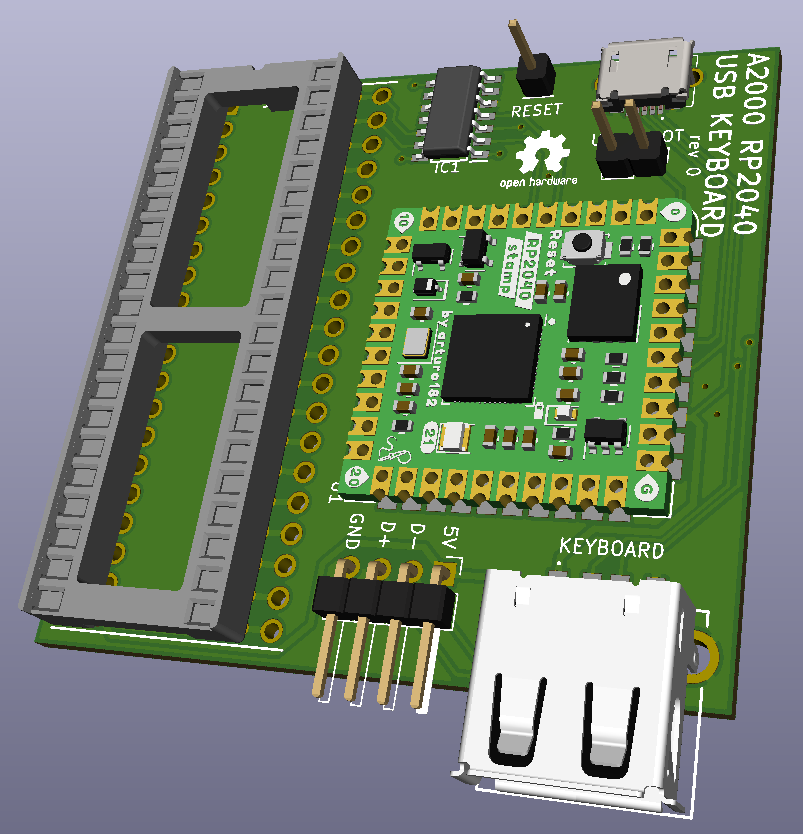
2 layers55.2 × 53 mmAmiga-2000-usb kb stamp, the printed circuit board in 3D

A USB keyboard adapter for the Amiga 2000 based on the Pi Stamp RP2040

Size
55.2 × 53 mm
Copper layers
2
Thickness
1.6 mm
Parts
14
Nets
80
Pads
206
Tracks, vias
139, 13
Pours
2
Routed
Yes
KiCad
KiCad 5 (file 20171130)
Created
8 Sep 2022
Updated
26 Jan 2024

Overview

Amiga-2000-usb kb stamp is an open-source printed circuit board by wiretap-retro, from the wiretap-retro/A2000-USB-Keyboard-Adapter-RP2040 repository on GitHub. It is a 2-layer board of 55.2 × 53 mm with 14 parts on 80 nets, routed with 139 tracks and 13 vias.

It is built around the TXS0104ED, USB1046-GF-0190-L-B-A and USB3075-30-A. Its parts include 7 connectors, 2 capacitors, 2 resistors and 2 ICs. It belongs with the retro computing and games boards and the RP2040 boards of this library.

Main components

3

README

README.md

A2000 USB Keyboard Adapter RP2040

A USB keyboard adapter for the Amiga 2000 based on the Pi Stamp RP2040

front-pcb

Intro

This is a USB keyboard adapter I designed a board for to use in the Amiga 2000. It is based on the amigahid-pico firmware by borb (nine), as well as my other A500 USB adapter. The KiCAD files, Gerbers, and BOM are in this repository. The completed board attaches to the CIA socket and provides a USB inputs for your interface device.

Parts

  • PCB: PCB's can be ordered from JLCPCB by uploading the Gerber files, but any PCB house should be able to make these since it is a simple/small design. (PCBway, OSH Park, AllPCB, etc.)
  • Pi Stamp RP2040: https://shop.pimoroni.com/products/rp2040-stamp
  • All other PCB mounted components were sourced at Mouser per the BOM. Other sources for the components could be Digikey, Farnell, RS, etc. depending on what is available in your location. Chip/component shortages may impact your ability to get everything all in one place. Substitutions may need to be made.
  • You will need to find a pin header to USB cable that suits your case needs, or a USB PCI bracket, possibly with an extension. (Amazon, Ebay, Aliexpress, etc.)

Building the Adapter

  • Solder the smallest SMD components first. (resistors, capacitors, logic level shifter, MicroUSB connector)
  • Solder the right angle pin connector. (USB header)
  • Solder the Pi Stamp RP2040 into place. You can solder directly onto the board, or optionally use the male and female headers to socket mount it. I recommend using the male and female pin headers so you can easily pull the RP2040 out if you need to use it again in the future on another project.
  • Solder the USB type-A connector.
  • Solder the vertical USB_BOOT header and reset pin into place. You can skip the reset pin if you're soldering a wire directly to the board instead.
  • Solder the two 20-pin machine pin headers to the bottom of the PCB.
  • Solder the 40-pin DIP socket.
  • I recommend checking all solder joints under magnification to ensure everything is connected with no shorts.

Flashing the Firmware

First off, a huge thank you to Nine for developing the amigahid-pico, as this design uses its firmware. Firmware is located at: https://github.com/borb/amigahid-pico/

  1. Build the firmware per the instructions at https://github.com/borb/amigahid-pico/blob/main/doc/installation.md
  2. Place a jumper on the USB_BOOT pin.
  3. Plug a MicroUSB cable to the PCB's MicroUSB port and plug the other end into the PC you just compiled the firmware on. It will then show up as a mass storage device.
  4. Remove the jumper from the USB_BOOT pin.
  5. Copy the amigahid-pico.uf2 file from the "build/src/" directory you compiled to the RP2040's mounted USB storage volume. It will then disconnect/reset.
  6. Disconnect the USB cable from the PC and keyboard adapter PCB.

Installation into the Amiga

  1. Gain access to your Amiga 2000 motherboard. This will require removing the top lid, as well as the PSU/3.5/5.25 mezzanine chassis.
  2. Remove the U300 CIA chip and install the keyboard adapter board into its place, paying attention to orientation.
  3. Plug the CIA chip into the DIP socket of the keyboard adapter, paying attention to orientation.
  4. Plug your USB cable into the pin header, or USB cable into the USB type-A port.
  5. Install the USB bracket into a spare ISA/Zorro slot.
  6. Connect a wire from the Reset pin on the keyboard adapter PCB to Gary chip Pin #5. I find that a small spring loaded test lead works best for easy install/removal.
  7. Plug the keyboard or wireless keyboard adapter into the newly installed USB port at the rear of the A2000.
  8. Boot the Amiga and test it out!

Optional Stuff

  • USB HID mouse support is included in Nine's firmware, but none of the mice I used would work with the A500 adapter which is nearly identical in terms of design. I use a DB9 connected OpenLaserMouse anyway, but maybe you'll have better luck testing various mice to see if one works. I know the firmware is still an in-progress project, or maybe I didn't do something right when I compiled the firmware.
  • Amiga keys are currently mapped to right and left windows keys. Before compiling the firmware, you can modify those keys if necessary at your own discretion.
  • Reset is initiated by Left Ctrl + Left Win + Right Win (CTRL + AMIGA + AMIGA)

Miscellaneous

This board is provided as-is and open source. This project is tested and working. It does not provide firmware and relies on a different project for the firmware as linked above. Review the design and build/test at your own risk. If you plan to sell this board, firmware is per the license at: https://github.com/borb/amigahid-pico/

Revisions

  • Rev 2 - Latest, fixed floating ground on the level shift logic.
  • Rev 1 - Adjust layout of chips and ports. Depreciated.
  • Rev 0 - Initial / Depreciated.

Parts

14
QtyValueFootprintReferences
2100nFCapacitor_SMD:C_0805_2012Metric_Pad1.15x1.40mm_HandSolderC1, C2
210kResistor_SMD:R_0805_2012Metric_Pad1.15x1.40mm_HandSolderR1, R4
1Amiga_ResetConnector_PinHeader_2.54mm:PinHeader_1x01_P2.54mm_VerticalJ7
1CIADIPS1544W70P254L5080H530Q40NJ3
1CIA-boardDIPS1544W70P254L5080H530Q40NJ4
1RP2040_StampSamacSys_Parts:RP2040_Stamp_THTU1
1TXS0104EDSOIC127P600X175-14NIC1
1USB1046-GF-0190-L-B-AUSB1046GF0190LBAJ8
1USB3075-30-AUSB307530AJ1
1USB_BOOTConnector_PinHeader_2.54mm:PinHeader_1x02_P2.54mm_VerticalJ9
1USB_HEADERConnector_PinHeader_2.54mm:PinHeader_1x04_P2.54mm_HorizontalJ2

The 13 most common of 14 parts.

Similar boards

  • 2 layers48.8 × 43.9 mmAmiga-500-usb kb stamp, the printed circuit board in 3D

    Amiga-500-usb kb stamp

    wiretap-retro/A500-USB-Keyboard-Adapter-RP2040

    A USB keyboard adapter for the Amiga 500 based on the Pi Stamp RP2040

    18 parts18
  • 6 layers90 × 153 mmBlackpants, the printed circuit board in 3D

    Blackpants

    o7-machinehum/Blackpants

    Open blackpants.kicadpro for the active A523 schematic and PCB. It replaces the A33 hierarchy and uses AXP717C + AXP323 with 2GB LPDDR4.

    300 parts189MIT
  • 2 layers38.5 × 34.3 mmEsp webcam, the printed circuit board in 3D

    Esp webcam

    pj-hoakari/esp-edge-device

    11 partsApache-2.0
  • 4 layers100 × 100 mmKvm switch, the printed circuit board in 3D

    Kvm switch

    Rithvik-Vadlamani/kvm-switch

    Four-layer HDMI/USB KVM design with STM32 firmware, supply supervision, and verification evidence

    170 parts
  • 2 layers124.5 × 68.6 mmOmnicontroller, the printed circuit board in 3D

    Omnicontroller

    rp958/omnicontroller

    OmniController is an all-in-one controller designed with retrogaming solutions in mind.

    53 partsCERN-OHL-S-2.0
  • 2 layers36 × 43 mmAsac fc rev a, the printed circuit board in 3D

    Asac fc rev a

    victorhook/asac-fc

    asac fc is an rp2040 based flight controller made for FPV drone flying

    119 parts52GPL-3.0
  • 4 layers33.8 × 46 mmOSW rakWisblock, the printed circuit board in 3D

    OSW rakWisblock

    a-allard/OSW_rakWisblock

    Derivative of the OSW using the RAK WisBlock

    70 parts2
  • 4 layers115 × 75 mmRF module, the printed circuit board in 3D

    RF module

    putsolardynamics/Telemetry-Module

    146 parts2MIT

Questions

How big is the Amiga-2000-usb kb stamp PCB?

It measures 55.2 × 53 mm and has 2 copper layers, 1.6 mm thick.

What parts does the Amiga-2000-usb kb stamp use?

14 parts, built around the TXS0104ED, USB1046-GF-0190-L-B-A and USB3075-30-A. The full list of its parts is on this page, with links to each part's symbol and footprint where PCBKit's library has them.

Where can I download the Amiga-2000-usb kb stamp KiCad files?

From the wiretap-retro/A2000-USB-Keyboard-Adapter-RP2040 repository on GitHub, at the commit this page was made from: the board is amiga-2000-usb-kb-stamp/amiga-2000-usb-kb-stamp.kicad_pcb. PCBKit opens the board in the browser, with nothing to install.

Can I use the Amiga-2000-usb kb stamp design in my own project?

Its repository states no licence, so its author keeps all rights: ask wiretap-retro before reusing the design.