 Patreon
 Ko-fi
2 layers75 × 75 mm

 rp958/omnicontroller
OmniController is an all-in-one controller designed with retrogaming solutions in mind.
Omnicontroller is an open-source printed circuit board by rp958, from the rp958/omnicontroller repository on GitHub, published under the CERN-OHL-S-2.0 licence. It is a 2-layer board of 124.5 × 68.6 mm with 53 parts on 54 nets, routed with 716 tracks and 198 vias.
It is built around the RP2040, W25Q128JVSIM and RKJXV122400R, with the ABM8-272-T3 and USB1046-GF-0190-L-B-A among its other parts. Its parts include 16 capacitors, 4 resistors, 3 ICs, 3 connectors and 1 crystal. It belongs with the RP2040 boards of this library.


OmniController is an Open Hardware / Open Source, all-in-one controller.
It was conceived with retrogaming solutions (such as emulators or FPGA) in mind but can accommodate to modern gaming as well. Its main goal is to cover original button layouts of most of the popular console controllers without having to remap buttons or use different controllers when playing games from different consoles libraries.
It uses the GP2040-CE firmware which is well known for its compatibility with most modern and retro platforms as well as its very low latency.
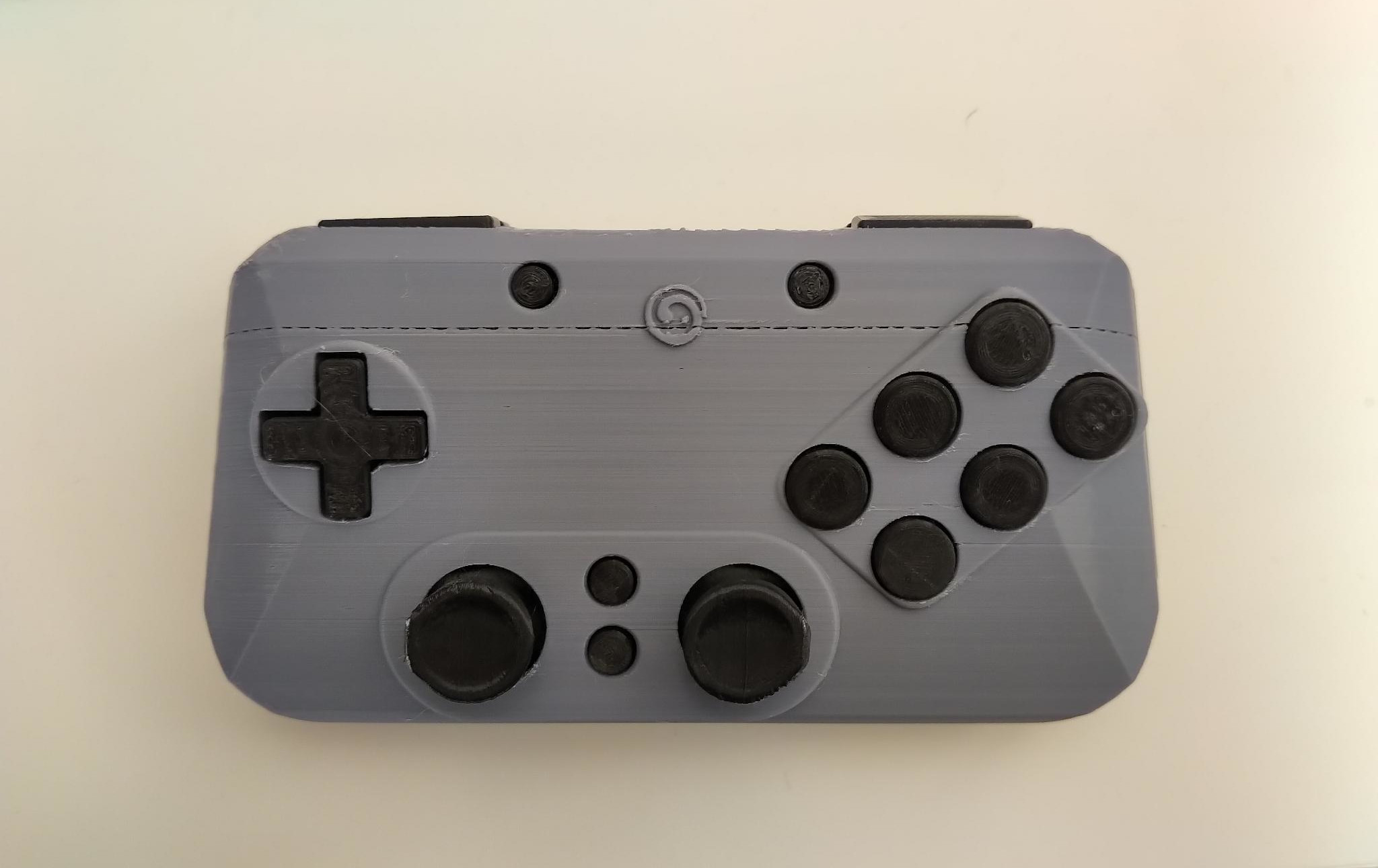
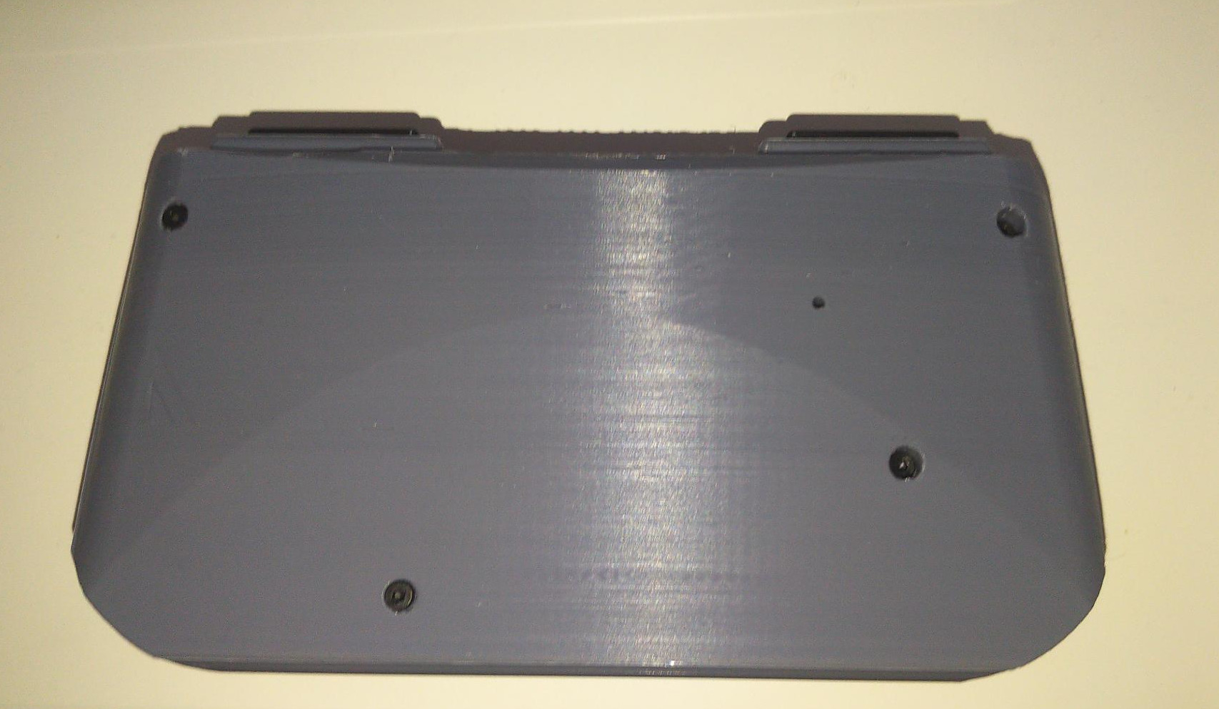
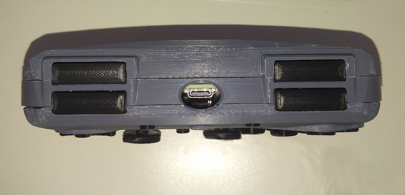
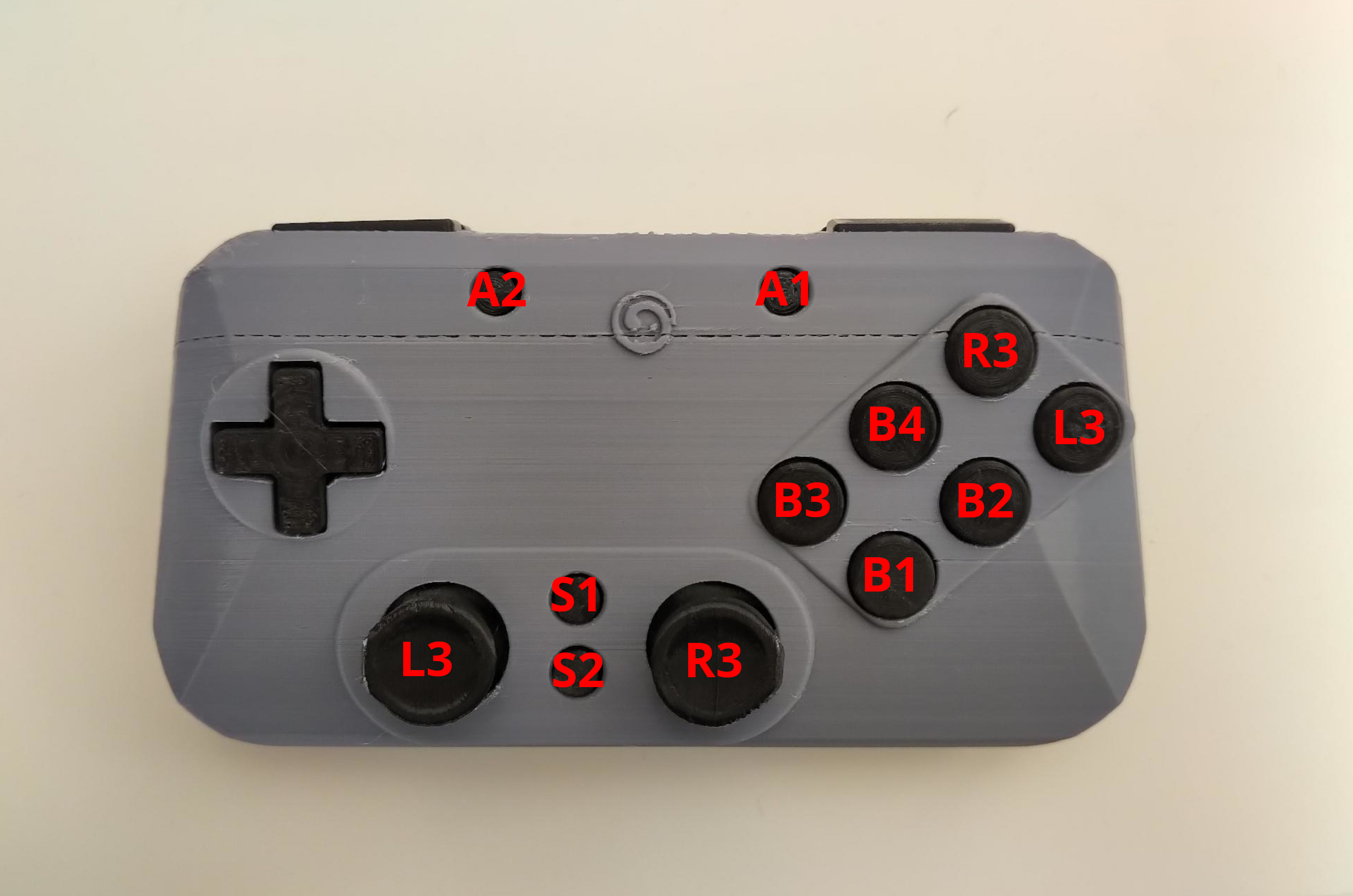
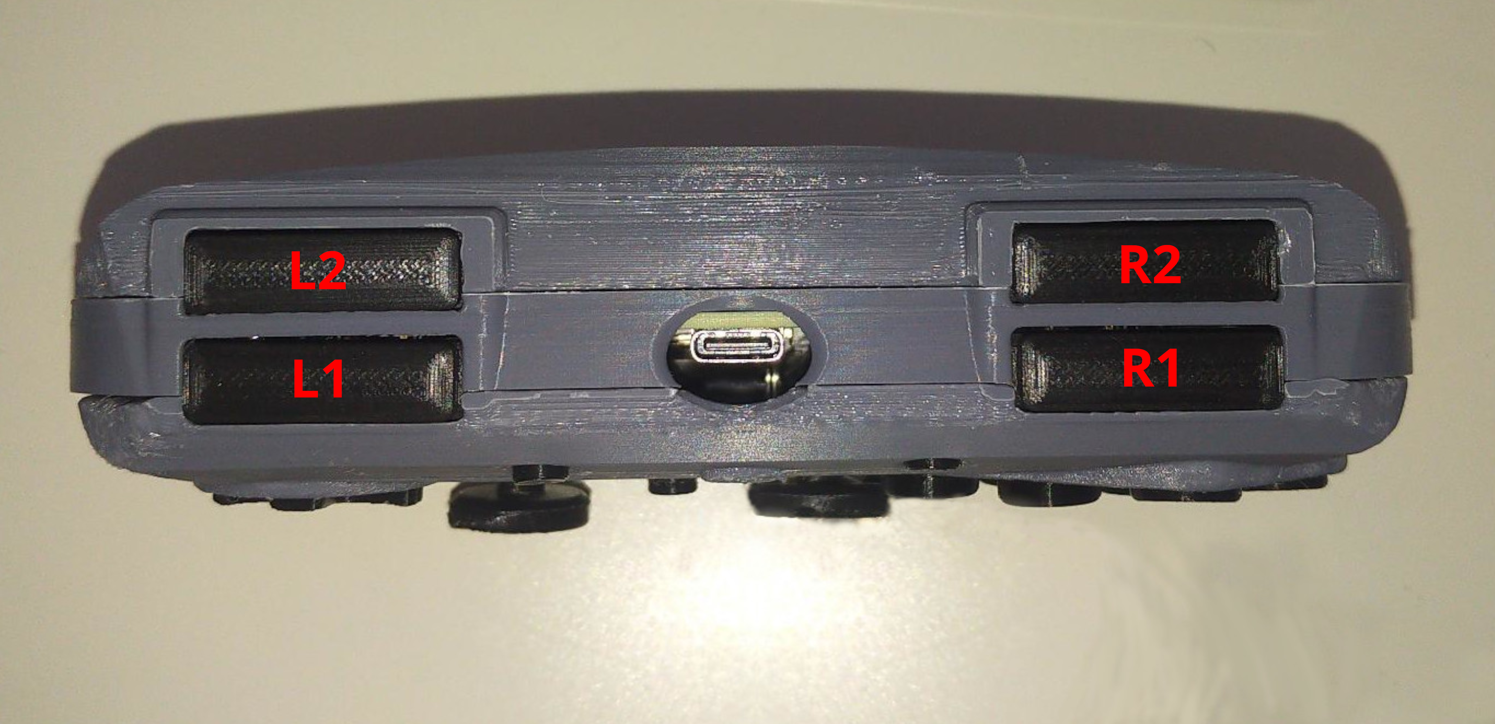
Please note that the double L3 and R3 buttons (the ones on the joysticks and the face buttons ones) are wired in hardware. That means that if you chose, for exemple, to remap L3 to a different button, both L3s will be remapped to that button. This is due to the fact that all GPIOs available in the firmware/microcontroller are already in use. It is unlikely that you will need to use both joysticks and 6 faces buttons at the same time.
Software:
Hardware:
Download and extract the latest OmniController release file.
All the necessary files for PCB fabrication are located in release/pcb/.
Bill of materials:
| Item# | Designation | Manufacturer | Part Number | Package | Value | Quantity |
|---|---|---|---|---|---|---|
| 1 | UP1, DOWN1, LEFT1, RIGHT1, Credit1, Menu1, SEL1, START1, A1, B1, bC1, X1, Y2, Z1, BOOT_SEL1 | Omron Electronics | B3FS-1000P | 15 | ||
| 2 | bR1, bR2, bL1, bL2 | Omron Electronics | B3F-3100 | 4 | ||
| 3 | C1, C2 | 0805 (2012 Metric) | 10u capacitor | 2 | ||
| 4 | C10, C11 | 0805 (2012 Metric) | 1u capacitor | 2 | ||
| 5 | C12, C13, C14, C3, C4, C5, C6, C7, C8, C9 | 0805 (2012 Metric) | 100n capacitor | 10 | ||
| 6 | C15, C16 | 0805 (2012 Metric) | 15p capacitor | 2 | ||
| 7 | LeftStick1, RightStick1 | Alps | RKJXV122400R | (THT) | 2 | |
| 8 | J1 | G-Switch | GT-USB-7010ASV | 1 | ||
| 9 | R1, R2 | 0805 (2012 Metric) | 27.4 ohms resistor | 2 | ||
| 10 | R3, R4 | 0805 (2012 Metric) | 1k resistor | 2 | ||
| 11 | U1 | Raspberry Pi | RP2040 | QFN-56 7×7mm | 1 | |
| 12 | U2 | Onsemi | NCP1117ST33T3G | SOT-223-3_TabPin2 | 1 | |
| 13 | U3 | Winbond | W25Q128JVSIM | SOIC 208-mil | 1 | |
| 14 | Y1 | Abracon | ABM8-272-T3 | Crystal SMD 3225 4Pin | 1 | |
| 15 | (Optionnal) J2 | GCT | USB1046-GF-0190-L-B-B | USB_A_Receptacle | 1 |
NOTE: J2 is only necessary for Host USB authentication mode. If not needed, can be left unpopulated.
NOTE: J3 is for development of and does not require populating.
You will need to print the following parts (all contained in release/case/).
Buttons:
Case:
For better printing results, it is recommended the following parts be sliced at an angle of 45 degrees and with supports:
All the other parts should be printed flat and do not require any support.
Please note that depending on the quality and precision of your print, you might have to sand some parts.
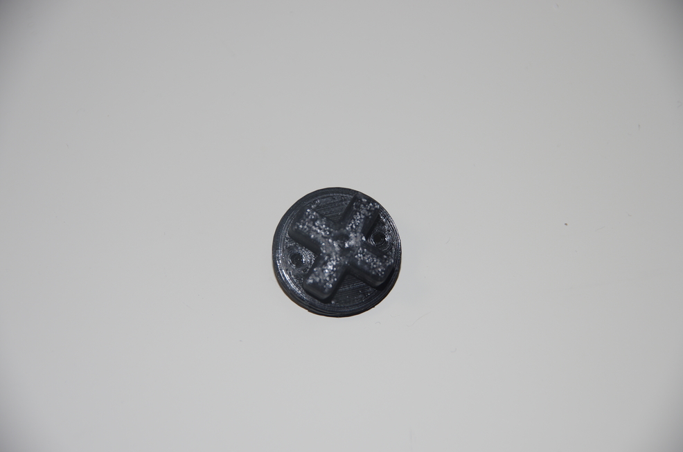
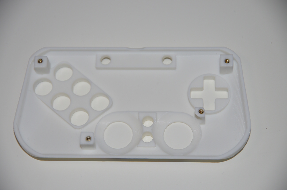
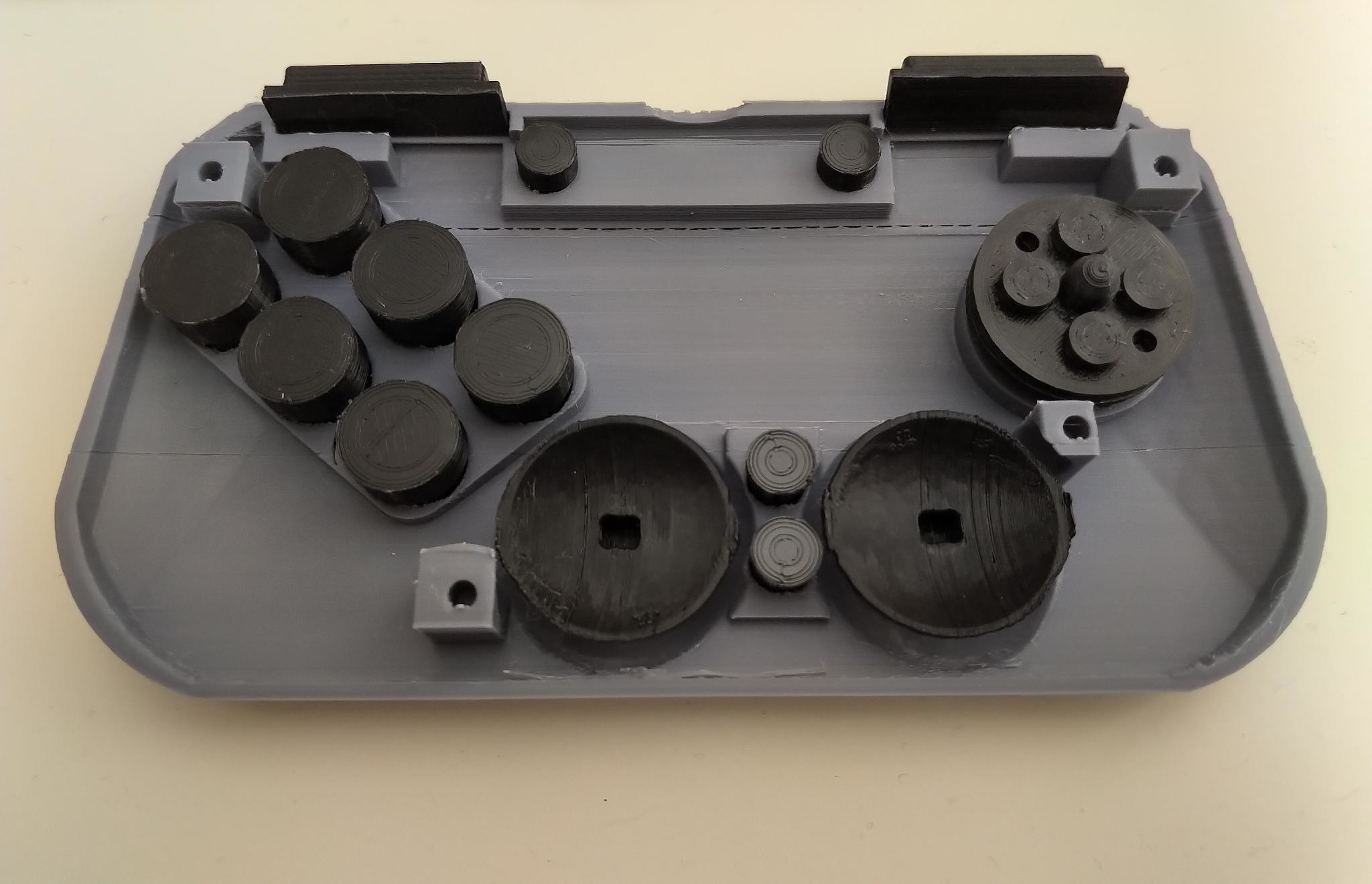
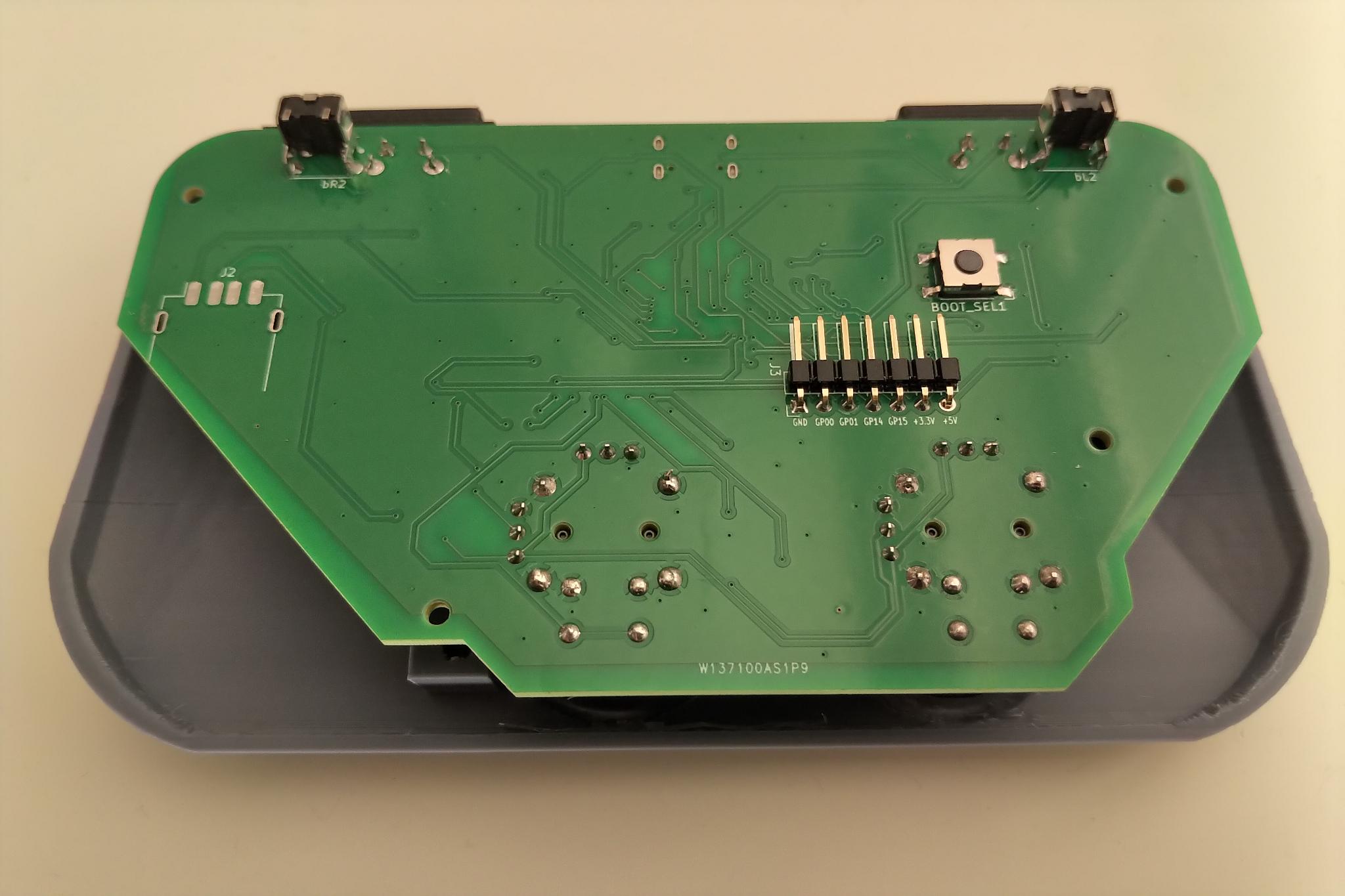
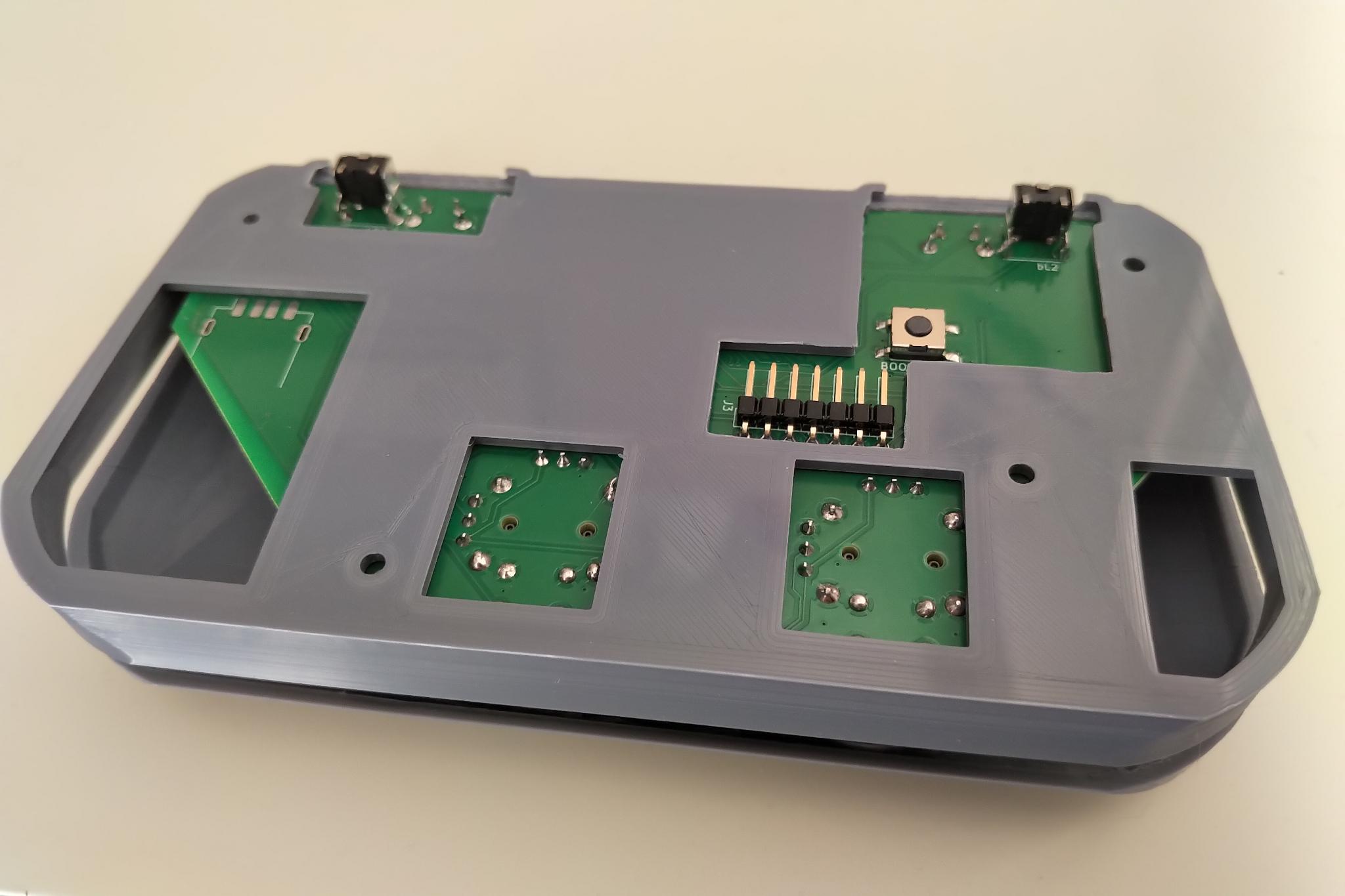
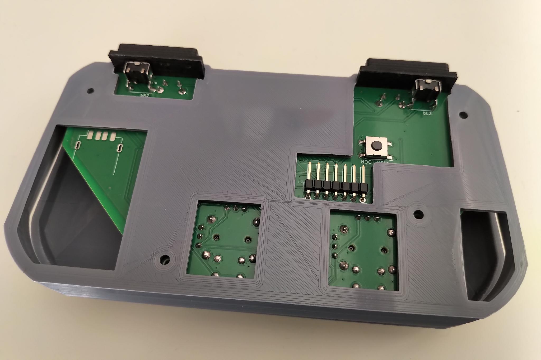
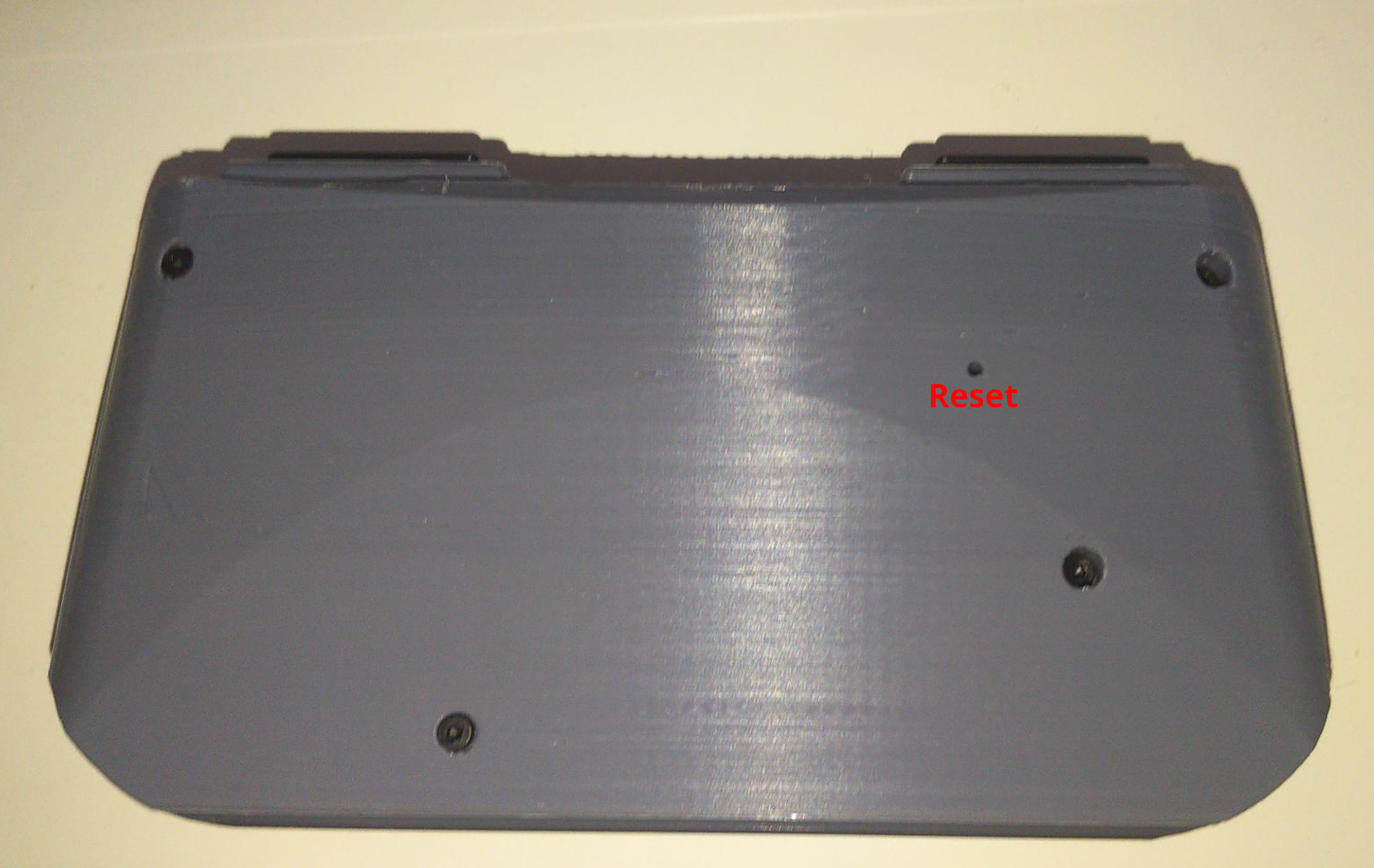
Please refer to the GP2040-CE installation documentation for more details.
Please refer to the GP2040-CE Web Configurator documentation for more details.
Please refer to the GP2040-CE usage documentation
In case of problems, you can use Hardware Tester's gamepad controller in order to make sure you controller is detected correctly and that all buttons are functioning.
Distributed under CERN-OHL-S version 2 or later. See licence text for more information.
Please e-mail me if you want to contribute, especially if you have experience in electronics engineering, CAD or manufacturing.
OmniController uses several KiCAD component footprints and models from the SnapEDA library.
Many thanks go to the GP2040-CE development team.
If you want to help funding this project, any contribution is greatly welcome. This can help me acquire some prototyping equipment and spend more time on the development. To do so, please use my:
Thank you.
| Qty | Value | Footprint | References |
|---|---|---|---|
| 14 | SW_Omron_B3FS-1000P | Button_Switch_SMD:SW_SPST_Omron_B3FS-100xP | A1, B1, bC1, BOOT_SEL1, Credit1, DOWN1, LEFT1, Menu1, RIGHT1, SEL1, UP1, X1, Y2, Z1 |
| 10 | 100n | Capacitor_SMD:C_0805_2012Metric | C3, C4, C5, C6, C7, C8, C9, C12, C13, C14 |
| 4 | SW_B3F-3100 | Buttons:SW_B3F-3100 | bL1, bL2, bR1, bR2 |
| 2 | 10u | Capacitor_SMD:C_0805_2012Metric | C1, C2 |
| 2 | 15p | Capacitor_SMD:C_0805_2012Metric | C15, C16 |
| 2 | 1k | Capacitor_SMD:C_0805_2012Metric | R3, R4 |
| 2 | 1u | Capacitor_SMD:C_0805_2012Metric | C10, C11 |
| 2 | 27.4 | Capacitor_SMD:C_0805_2012Metric | R1, R2 |
| 2 | RKJXV122400R | Controllers:SW_RKJXV122400R | LeftStick1, RightStick1 |
| 1 | ABM8-272-T3 | Crystal:Crystal_SMD_3225-4Pin_3.2x2.5mm | Y1 |
| 1 | Conn_01x07_Pin | Connector_PinHeader_2.54mm:PinHeader_1x07_P2.54mm_Horizontal | J3 |
| 1 | G-Switch GT-USB-7010ASV | Connector_USB:USB_C_Receptacle_G-Switch_GT-USB-7010ASV | J1 |
| 1 | LOGO | Logo:logo | G*** |
| 1 | NCP1117ST33T3G | Package_TO_SOT_SMD:SOT-223-3_TabPin2 | U2 |
| 1 | RP2040 | Package_DFN_QFN:QFN-56-1EP_7x7mm_P0.4mm_EP3.2x3.2mm | U1 |
| 1 | SW_Omron_B3FS-1000 | Button_Switch_SMD:SW_SPST_Omron_B3FS-100xP | START1 |
| 1 | USB1046-GF-0190-L-B | Connector_USB:USB_A_Receptacle_GCT_USB1046 | J2 |
| 1 | W25Q128JVSIM | Package_SO:SOIC-8_5.3x5.3mm_P1.27mm | U3 |
The 49 most common of 53 parts.

mrspieb/HW-FanControl
Everything required to build the PCB and case of the ventilation fan controller

PartialScience/Custom-RP2040-Dev-Board
First-PCB project: minimal RP2040 microcontroller dev board (W25Q128JV flash, 12 MHz crystal, NCP1117-3.3 LDO, micro-B USB). KiCad sources, BOM, and Inventor enclosure model.

o7-machinehum/Blackpants
Open blackpants.kicadpro for the active A523 schematic and PCB. It replaces the A33 hierarchy and uses AXP717C + AXP323 with 2GB LPDDR4.

wiretap-retro/A2000-USB-Keyboard-Adapter-RP2040
A USB keyboard adapter for the Amiga 2000 based on the Pi Stamp RP2040


Rithvik-Vadlamani/kvm-switch
Four-layer HDMI/USB KVM design with STM32 firmware, supply supervision, and verification evidence

It measures 124.5 × 68.6 mm and has 2 copper layers, 1.6 mm thick.
53 parts, built around the RP2040, W25Q128JVSIM, RKJXV122400R and ABM8-272-T3. The full list of its parts is on this page, with links to each part's symbol and footprint where PCBKit's library has them.
From the rp958/omnicontroller repository on GitHub, at the commit this page was made from: the board is src/pcb/omnicontroller.kicad_pcb and its schematic src/pcb/omnicontroller.kicad_sch. PCBKit opens the board in the browser, with nothing to install.
Its repository publishes it under the CERN-OHL-S-2.0 licence: you may reuse it on that licence's terms (keep the author's notice, and for a copyleft licence share your changes alike).