4 layers86.3 × 25 mm

 will127534/cf-mp3-player16
A simple MP3/WAV/FLAC player using CF card
Cf mp3-player is an open-source printed circuit board by will127534, from the will127534/cf-mp3-player repository on GitHub, published under the MIT licence. It is a 4-layer board of 62.8 × 61.7 mm with 119 parts on 126 nets, routed with 835 tracks and 322 vias.
It is built around the RP2354B, TPSM82821SILR and APS6404L-3SQR-SN, with the BQ24075RGT, ECS-2520MV-240-DN-TR and LP5912-3.3DRVR among its other parts. Its parts include 44 capacitors, 42 resistors, 8 ICs, 6 connectors and 6 switches. It belongs with the RP2350 boards of this library.


KiCad 8 design files for the rev3 CF MP3 Player board, the board the firmware
in this repository targets (BOARD_REV3=1, the default build). The
silkscreen reads "CF Card MP3 Player V2.1"; the firmware and docs call this
board rev3.
| Top | Bottom (seen from below) |
|---|---|
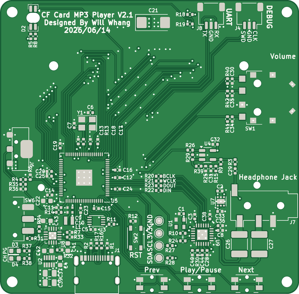 | 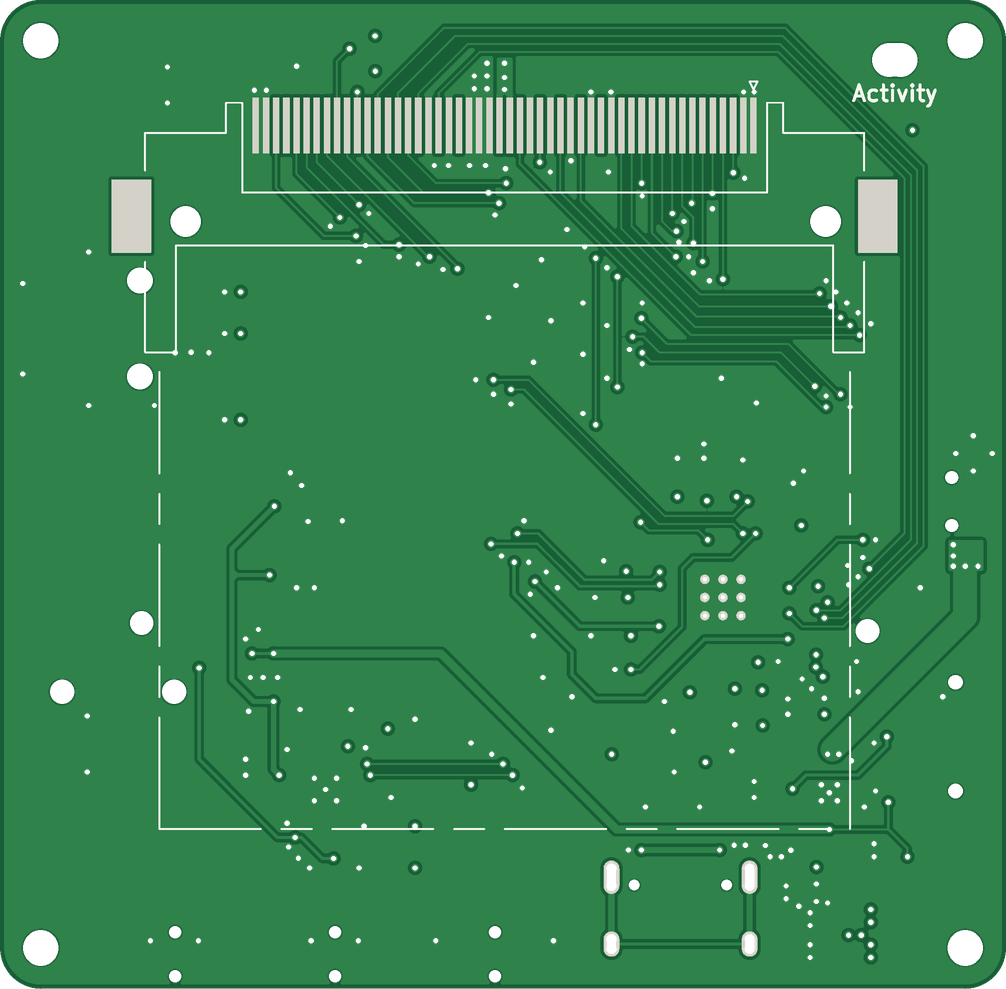 |
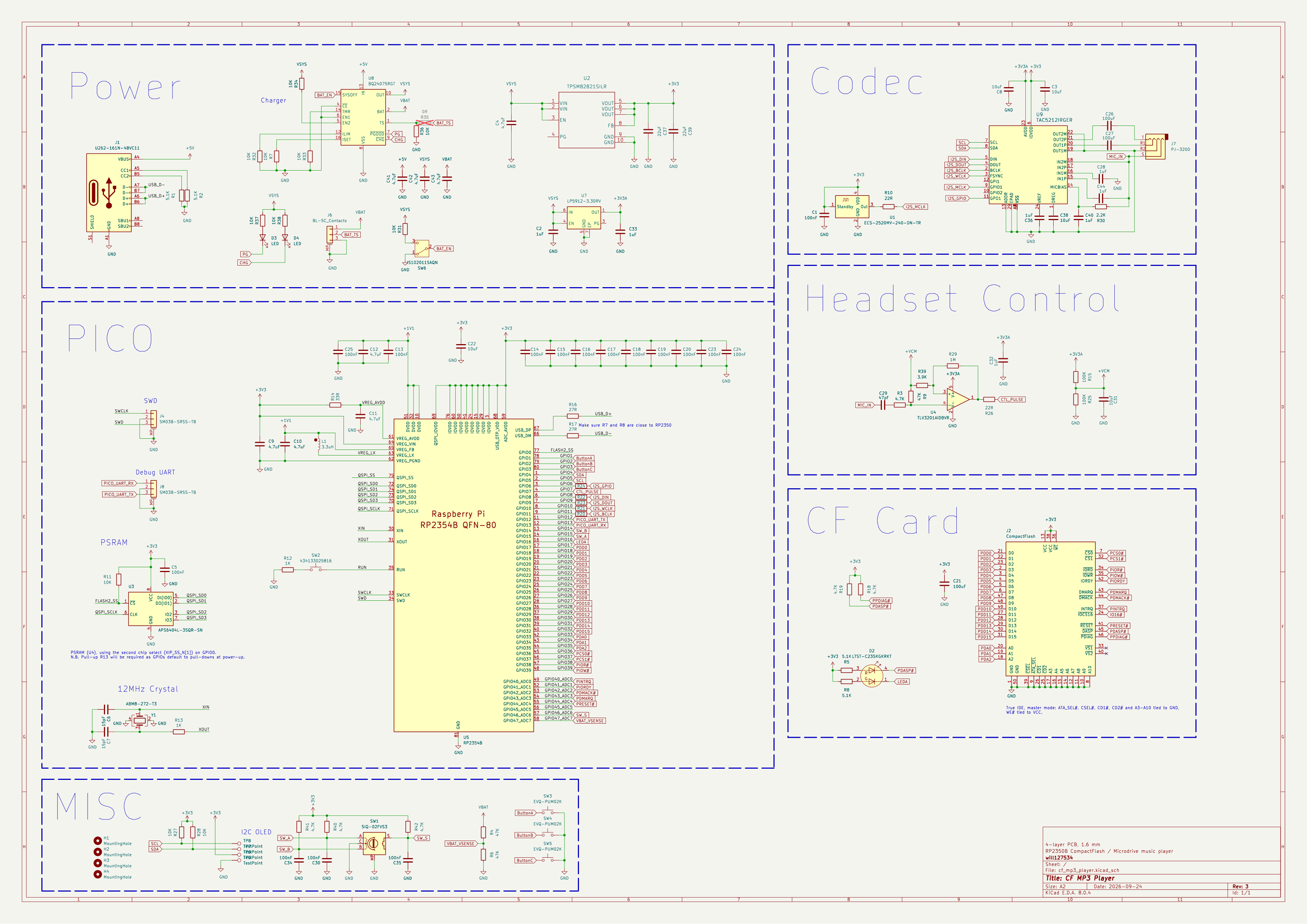
The schematic is also available as a PDF.
| File | Contents |
|---|---|
cf_mp3_player.kicad_pro, .kicad_sch, .kicad_pcb | KiCad 8 project: schematic and 4-layer PCB |
cf_mp3_player.kicad_sym, sym-lib-table | Project symbol library (CompactFlash True IDE connector J2, TAC5212 codec U9) |
cf_mp3_player_schematic.pdf | Schematic |
cf_mp3_player.step | 3D model of the assembled board |
bom/cf_mp3_player_bom.csv | Bill of materials, grouped by part |
bom/cf_mp3_player_ibom.html | Interactive BOM (open it in a browser) |
fabrication/cf_mp3_player_rev3_gerbers.zip | Gerber X2 and Excellon drill files |
fabrication/cf_mp3_player_rev3_pos.csv | Pick-and-place positions (DNP parts excluded) |
images/ | Board renders and schematic image |
export_outputs.py | Regenerates everything above except the STEP file |
The Gerbers match the fabricated rev3 boards. Compared with the set sent to fab on 2026-06-19, the only differences are the board's position on the sheet and one F.Cu copper-pour outline that moved by up to 0.12 mm when the zones were refilled. Tracks, pads, vias, mask, paste, silkscreen, outline and drill hits are unchanged.
Board: 62.8 x 61.7 mm, 4 layers, 1.6 mm, four M2 mounting holes.
Needs KiCad 8 (kicad-cli) and Python 3 with numpy, Pillow and PyMuPDF. The
interactive BOM also needs the
InteractiveHtmlBom
plugin; the script skips it if the plugin is not installed.
python hardware/export_outputs.pyManufacturer and MPN fields in the
schematic. Passives are listed by value and package only.${KIPRJMOD}/*.step) that
are not in this repository, so KiCad's 3D viewer leaves those parts out.
cf_mp3_player.step contains the complete assembly.Compared against the TAC5212 datasheet (SLASF23A, Figure 9-1 and the 9.4.2 layout example). The typical-application figure there is labelled "TAC5212 / TAC5112" because the two parts share a pinout.
| Pin | Datasheet | This board |
|---|---|---|
| AVDD (23) | 10 uF + 0.1 uF | C8 10 uF at the pin; C33 1 uF (LDO output) nearby. No 0.1 uF. |
| IOVDD (6) | 10 uF + 0.1 uF | C3 10 uF at the pin; C1 100 nF 3.6 mm away. |
| DREG (1) | 10 uF + 0.1 uF | C38 10 uF. No 0.1 uF. |
| VREF (24) | 1 uF minimum | C36 1 uF |
| MICBIAS (14) | 1 uF, low ESR | C40 1 uF |
| IN1P / IN1M (15/16) | AC coupling; quick-charge default assumes up to 1 uF | C44 / C28 1 uF, IN1M grounded after its capacitor (single-ended AC-coupled, Figure 7-17) |
The headset mic (jack sleeve, MIC_IN) is biased from MICBIAS through R30
(2.2K), AC-coupled into IN1P, and DC-coupled into IN2M so the firmware can
read the remote buttons with the incremental ADC. With the default 5 kohm
input impedance the 1 uF coupling capacitor puts the high-pass corner at
about 32 Hz. Use low-voltage-coefficient (X7R) capacitors for C44 and C28.
AVDD runs at 3.3 V: the firmware leaves AVDD_MODE at its 3.3 V setting and
programs VREF to 2.5 V, which the datasheet only allows with a 3.3 V AVDD.
U7 is therefore the LP5912-3.3.
For a future spin: add 0.1 uF capacitors next to AVDD and DREG.
All of these are in the design files:
Pin map and codec routing: docs/HARDWARE.md. Known board-level limitations (cold power-on click, Microdrive read coupling, VBAT reference): docs/HARDWARE.md.
| Qty | Value | Footprint | References |
|---|---|---|---|
| 16 | 100nF | Capacitor_SMD:C_0402_1005Metric | C1, C5, C13, C14, C15, C16, C17, C18, C19, C20, C23, C24, C25, C30, C34, C35 |
| 11 | 10K | Resistor_SMD:R_0402_1005Metric | R7, R11, R27, R28, R31, R32, R33, R34, R36, R37, R38 |
| 7 | 1uF | Capacitor_SMD:C_0402_1005Metric | C2, C28, C32, C33, C36, C40, C44 |
| 7 | 27R | Resistor_SMD:R_0402_1005Metric | R16, R17, R20, R21, R22, R23, R24 |
| 6 | 4.7K | Resistor_SMD:R_0402_1005Metric | R3, R18, R19, R40, R41, R42 |
| 4 | 10uF | Capacitor_SMD:C_0402_1005Metric | C3, C8, C31, C38 |
| 4 | 4.7uF | Capacitor_SMD:C_0603_1608Metric | C4, C41, C42, C43 |
| 4 | 5.1K | Resistor_SMD:R_0402_1005Metric | R1, R2, R5, R8 |
| 4 | MountingHole | MountingHole:MountingHole_2.2mm_M2 | H1, H2, H3, H4 |
| 4 | TestPoint | TestPoint:TestPoint_Pad_D1.5mm | TP5, TP6, TP7, TP8 |
| 3 | 47K | Resistor_SMD:R_0402_1005Metric | R4, R6, R9 |
| 3 | EVQ-PUM02K | Button_Switch_SMD:Panasonic_EVQPUM_EVQPUD | SW3, SW4, SW5 |
| 2 | 100K | Resistor_SMD:R_0402_1005Metric | R15, R25 |
| 2 | 100uF | Capacitor_SMD:C_1812_4532Metric | C26, C27 |
| 2 | 15pF | Capacitor_SMD:C_0402_1005Metric | C6, C7 |
| 2 | 1K | Resistor_SMD:R_0402_1005Metric | R12, R13 |
| 2 | 22R | Resistor_SMD:R_0402_1005Metric | R10, R26 |
| 2 | 22uF | Capacitor_SMD:C_0805_2012Metric | C37, C39 |
| 2 | 4.7uF | RP2350_80QFN_minimal:C_0402_1005Metric_small_pads | C9, C10 |
| 2 | 4.7uF | Capacitor_SMD:C_0402_1005Metric | C11, C12 |
| 2 | LED | LED_SMD:LED_0603_1608Metric | D3, D4 |
| 2 | SM03B-SRSS-TB | Connector_JST:JST_SH_SM03B-SRSS-TB_1x03-1MP_P1.00mm_Horizontal | J4, J8 |
| 1 | 0R | Resistor_SMD:R_0402_1005Metric | R35 |
| 1 | 100uF | Capacitor_Tantalum_SMD:CP_EIA-6032-20_AVX-F | C21 |
| 1 | 10uF | Capacitor_SMD:C_0603_1608Metric | C22 |
| 1 | 1M | Resistor_SMD:R_0402_1005Metric | R29 |
| 1 | 2.2K | Resistor_SMD:R_0402_1005Metric | R30 |
| 1 | 3.3uH | RP2350_80QFN_minimal:L_pol_2016 | L1 |
| 1 | 3.9K | Resistor_SMD:R_0402_1005Metric | R39 |
| 1 | 33R | Resistor_SMD:R_0402_1005Metric | R14 |
| 1 | 434133025816 | Button_Switch_SMD:SW_Push_1P1T_NO_Vertical_Wuerth_434133025816 | SW2 |
| 1 | 47pF | Capacitor_SMD:C_0402_1005Metric | C29 |
| 1 | ABM8-272-T3 | Crystal:Crystal_SMD_3225-4Pin_3.2x2.5mm | Y1 |
| 1 | APS6404L-3SQR-SN | Package_SON:Winbond_USON-8-1EP_3x2mm_P0.5mm_EP0.2x1.6mm | U3 |
| 1 | BL-5C_Contacts | BL-4C:bl-4C | J6 |
| 1 | BQ24075RGT | Package_DFN_QFN:VQFN-16-1EP_3x3mm_P0.5mm_EP1.6x1.6mm | U8 |
| 1 | CompactFlash | Connector_Card:CF-Card_3M_N7E50-A516xx-30 | J2 |
| 1 | ECS-2520MV-240-DN-TR | Oscillator:Oscillator_SMD_Abracon_ASDMB-4Pin_2.5x2.0mm | U1 |
| 1 | JS102011SAQN | Button_Switch_SMD:SW_SPDT_CK_JS102011SAQN | SW6 |
| 1 | LP5912-3.3DRV | Package_SON:WSON-6-1EP_2x2mm_P0.65mm_EP1x1.6mm_ThermalVias | U7 |
| 1 | LTST-C235KGKRKT | LED_SMD:LED_LiteOn_LTST-C235KGKRKT | D2 |
| 1 | PJ-320D | Connector_Audio:Jack_3.5mm_PJ320D_Horizontal | J7 |
| 1 | RP2354B | RP2350_80QFN_minimal:RP2350-QFN-80-1EP_10x10_P0.4mm_EP3.4x3.4mm_ThermalVias | U5 |
| 1 | SIQ-02FVS3 | footprints:SW_Mitsumi_SIQ-02FVS3_Encoder_Slide_SMD | SW1 |
| 1 | TAC5212IRGER | footprints:VQFN24_RGE_CORNERPADS_TEX | U9 |
| 1 | TLV3201AIDBVR | Package_TO_SOT_SMD:SOT-23-5 | U4 |
| 1 | TPSM82821SILR | footprints:TPSM82821SILR | U2 |
| 1 | U262-161N-4BVC11 | Connector_USB:USB_C_Receptacle_XKB_U262-16XN-4BVC11 | J1 |
It measures 62.8 × 61.7 mm and has 4 copper layers, 1.6 mm thick.
119 parts, built around the RP2354B, TPSM82821SILR, APS6404L-3SQR-SN and BQ24075RGT. The full list of its parts is on this page, with links to each part's symbol and footprint where PCBKit's library has them.
From the will127534/cf-mp3-player repository on GitHub, at the commit this page was made from: the board is hardware/cf_mp3_player.kicad_pcb and its schematic hardware/cf_mp3_player.kicad_sch. PCBKit opens the board in the browser, with nothing to install.
Its repository publishes it under the MIT licence: you may reuse it on that licence's terms (keep the author's notice, and for a copyleft licence share your changes alike).


OpenDrone-hw/OpenFC-Lite
Open-source Betaflight flight controller. RP2354B, 30.5x30.5 mm, 6-layer, 3-8S, CERN-OHL-S-2.0.


renzbagaporo/metalclaw-pico-rp2
An RP2354B board for testing firmware on a Raspberry Pi Pico or Pico 2. Metalclaw firmware provides Python-controlled peripheral emulation and a USB debug probe.


