4 layers159 × 132.3 mm

 Ajstros/hdmi-snake
Hardware design for playing snake over HDMI.
Hdmi snake is an open-source printed circuit board by Ajstros, from the Ajstros/hdmi-snake repository on GitHub. It is a 4-layer board of 86.3 × 25 mm with 62 parts on 71 nets, routed with 696 tracks and 81 vias.
It is built around the ESP32-C3-WROOM-02-N4, FT231XS-U and TPSM82821SILR, with the TLV75801PDBVR-MS, TPD4E02B04DQAR and 150060BS75000 among its other parts. Its parts include 23 resistors, 12 capacitors, 8 diodes, 5 ICs and 5 connectors. It belongs with the interfaces and adapters boards and the ESP32 and RISC-V boards of this library.


This board was designed to facilitate Bluetooth control of an HDMI video device to display simple pixel graphics for playing the game snake. The design allows 3-bit color, one for each of RGB, due to constraints of the ESP32-C3 microcontroller's available GPIO pins. Differential impedances are considered for the USB data lines and the HDMI TMDS lines, and length matching is considered for the R, G, B, and IDCLK lines driving the HDMI transmitter. The board is meant to be powered from a USB 2.0 port. A DigiKey list of parts is available here. The block design is shown below and a PDF of the schematic is available in the repo under kicad/hdmi_snake.pdf.
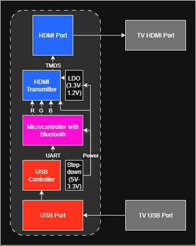
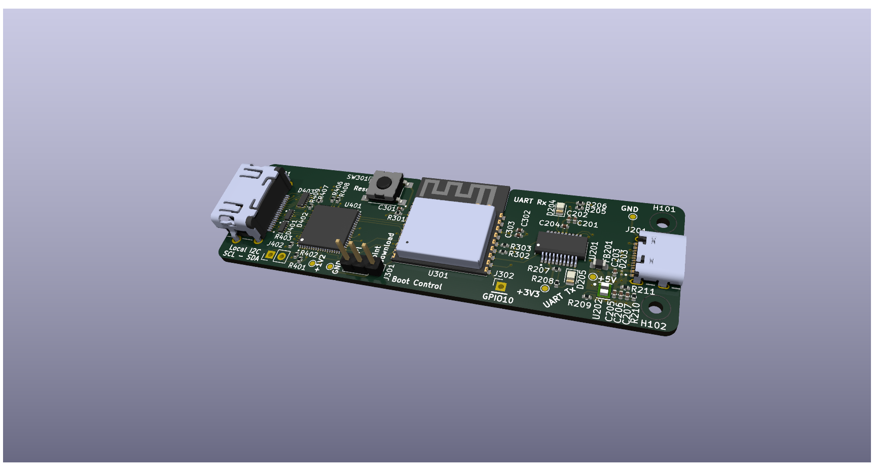
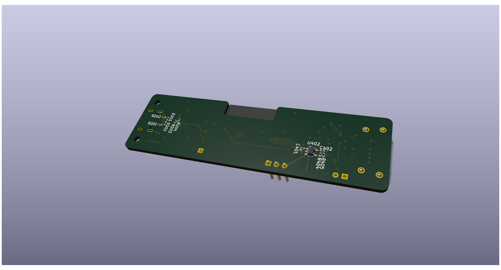
This repo includes the block design and full KiCAD design with local symbols, footprints, datasheets, and 3D models. Images of the board model are shown below.
PCB design final project for ETLS 684 at the University of St. Thomas MSEE program.
| Qty | Value | Footprint | References |
|---|---|---|---|
| 4 | 0 | Resistor_SMD:R_0402_1005Metric | R203, R204, R302, R303 |
| 4 | 24 | Resistor_SMD:R_0402_1005Metric | R205, R206, R207, R208 |
| 4 | 4.7u | Capacitor_SMD:C_0402_1005Metric | C202, C204, C401, C402 |
| 3 | 10u | Capacitor_SMD:C_0402_1005Metric | C205, C206, C302 |
| 3 | 4.7k | Resistor_SMD:R_0402_1005Metric | R401, R402, R403 |
| 2 | 100k | Resistor_SMD:R_0402_1005Metric | R209, R211 |
| 2 | 10k | Resistor_SMD:R_0402_1005Metric | R301, R407 |
| 2 | 2.2k | Resistor_SMD:R_0402_1005Metric | R406, R408 |
| 2 | 5.1k | Resistor_SMD:R_0402_1005Metric | R201, R202 |
| 2 | ESD321 | Diode_SMD:D_0402_1005Metric | D201, D202 |
| 2 | GND | TestPoint:TestPoint_Pad_D1.0mm | TP104, TP105 |
| 2 | MountingHole | MountingHole:MountingHole_2.2mm_M2 | H101, H102 |
| 2 | TPD4E02B04DQAR | hdmi_snake_footprint_library:DIO_TPD4E02B04DQAR | D401, D402 |
| 1 | +1V2 | TestPoint:TestPoint_Pad_D1.0mm | TP103 |
| 1 | +3V3 | TestPoint:TestPoint_Pad_D1.0mm | TP102 |
| 1 | +5V | TestPoint:TestPoint_Pad_D1.0mm | TP101 |
| 1 | 0.1u | Capacitor_SMD:C_0402_1005Metric | C303 |
| 1 | 100n | Capacitor_SMD:C_0402_1005Metric | C201 |
| 1 | 10n | Capacitor_SMD:C_0402_1005Metric | C203 |
| 1 | 120p | Capacitor_SMD:C_0402_1005Metric | C207 |
| 1 | 150060BS75000 | LED_SMD:LED_0805_2012Metric | D204 |
| 1 | 150060RS75000 | LED_SMD:LED_0805_2012Metric | D205 |
| 1 | 1u | Capacitor_SMD:C_0402_1005Metric | C301 |
| 1 | 4.3k | Resistor_SMD:R_0402_1005Metric | R409 |
| 1 | 450k | Resistor_SMD:R_0402_1005Metric | R210 |
| 1 | 500k | Resistor_SMD:R_0402_1005Metric | R404 |
| 1 | 590k | Resistor_SMD:R_0402_1005Metric | R405 |
| 1 | Boot Control | Connector_PinHeader_2.54mm:PinHeader_1x03_P2.54mm_Vertical | J301 |
| 1 | ESD441 | Diode_SMD:D_0201_0603Metric | D203 |
| 1 | ESP32-C3-WROOM-02-N4 | hdmi_snake_footprint_library:MODULE_ESP32-C3-WROOM-02-H4 | U301 |
| 1 | FT231XS-U | hdmi_snake_footprint_library:SOP63P600X175-20N | U201 |
| 1 | GPIO10 | Connector_PinHeader_2.54mm:PinHeader_1x01_P2.54mm_Vertical | J302 |
| 1 | Local I2C | Connector_PinHeader_2.54mm:PinHeader_1x02_P2.54mm_Vertical | J402 |
| 1 | MI0805K400R-10 | Inductor_SMD:L_0805_2012Metric | FB201 |
| 1 | Reset | Button_Switch_SMD:SW_SPST_Omron_B3FS-100xP | SW301 |
| 1 | SII9022 | hdmi_snake_footprint_library:QFN50P1000X1000X90-73N | U401 |
| 1 | SS-53000-001 | hdmi_snake_footprint_library:STEWART_SS-53000-001 | J401 |
| 1 | TLV75801PDBVR | hdmi_snake_footprint_library:SOT95P280X145-5N | U402 |
| 1 | TPD6E05U06RVZR | hdmi_snake_footprint_library:TPD6E05U06RVZR | D403 |
| 1 | TPSM82821SILR | hdmi_snake_footprint_library:SIL0010D-MFG | U202 |
| 1 | USB4105-GF-A | hdmi_snake_footprint_library:GCT_USB4105-GF-A | J201 |
It measures 86.3 × 25 mm and has 4 copper layers, 1.58 mm thick.
62 parts, built around the ESP32-C3-WROOM-02-N4, FT231XS-U, TPSM82821SILR and TLV75801PDBVR-MS. The full list of its parts is on this page, with links to each part's symbol and footprint where PCBKit's library has them.
From the Ajstros/hdmi-snake repository on GitHub, at the commit this page was made from: the board is kicad/hdmi_snake/hdmi_snake.kicad_pcb and its schematic kicad/hdmi_snake/HDMI.kicad_sch. PCBKit opens the board in the browser, with nothing to install.
Its repository states no licence, so its author keeps all rights: ask Ajstros before reusing the design.


ut-ras/robomaster_hardware
Welcome! Please read the Wiki page for information on how to set up your computer and an overview of the projects in this repository.

ad4363/LuX-ray-PCBs
A repository containing KiCad schematic and pcb files for a wireless radiation detector testing interface

KaitoTLex/RoboRyo
This is team1280's replacement for the Robo Rio for more redundant and less annoying controls.

DanielCusi/MoonJelly-robotics-PCB
Robotics PCB designed for Eurobot used by Wolvineers.