Skip to the content
2 layers160 × 24 mmJu touch, the printed circuit board in 3D

Jubeat Style Controller

Size
160 × 24 mm
Copper layers
2
Thickness
1.6 mm
Parts
20
Nets
70
Pads
180
Tracks, vias
208, 30
Pours
32
Routed
Yes
KiCad
KiCad 8.0 (file 20240108)
Created
23 Oct 2024
Updated
29 Apr 2026

Overview

Ju touch is an open-source printed circuit board by whowechina, from the whowechina/ju_pico repository on GitHub. It is a 2-layer board of 160 × 24 mm with 20 parts on 70 nets, routed with 208 tracks and 30 vias.

It is built around the U262-161N-4BVC11. Its parts include 4 diodes, 3 capacitors, 3 resistors and 3 ICs.
Main components

1

README

README.md

Ju Pico - Jubeat Style Mini Controller

点这里可以切换到中文版

Features:

  • There're two versions. Ju Pico is designed for 15.6" portable monitor, Ju Pico+ is designed for 21.5" monitor.
  • It's small but closely replicates the feel of the arcade.
  • Can be placed in 4 different orientations (rotations).
  • Command line for configurations.
  • All source files open.

Thanks to many respectful guys/companies who made their tools or materials free or open source (KiCad, OnShape, InkScape, Raspberry things).

Special thanks to community projects and developers. And also these projects:

My Other Projects

You can check out my other cool projects.

Disclaimer

I made this project in my personal time with no financial benefit or sponsorship. I will continue to improve the project. I have done my best to ensure that everything is accurate and functional, there's always a chance that mistakes may occur. I cannot be held responsible for any loss of your time or money that may result from using this open source project. Thank you for your understanding.

About the License

It's CC-NC. So DIY for yourself and for your friend, don't make money from it. And plagiarism that doesn’t even dare to mention the original author is not acceptable. Please note that pooling orders and group buying for raw materials is acceptable. Selling off any leftover components without profit is also acceptable.

If you're interested in buying from me, or for commercial use, please contact me (Discord, QQ group, Wechat group or leave your contact in issue section).

My Discord Invitation

https://discord.gg/M8f2PPQFEA

HOW TO BUILD JU PICO

PCB and Components

  • Go JLCPCB and make order with the gerber zip files (latest Production\PCB\ju_io_xxx.zip and Production\PCB\ju_button_xxx.zip), regular FR-4 board, black color, 1.6mm thickness. For Ju Pico+, please use button215 version.
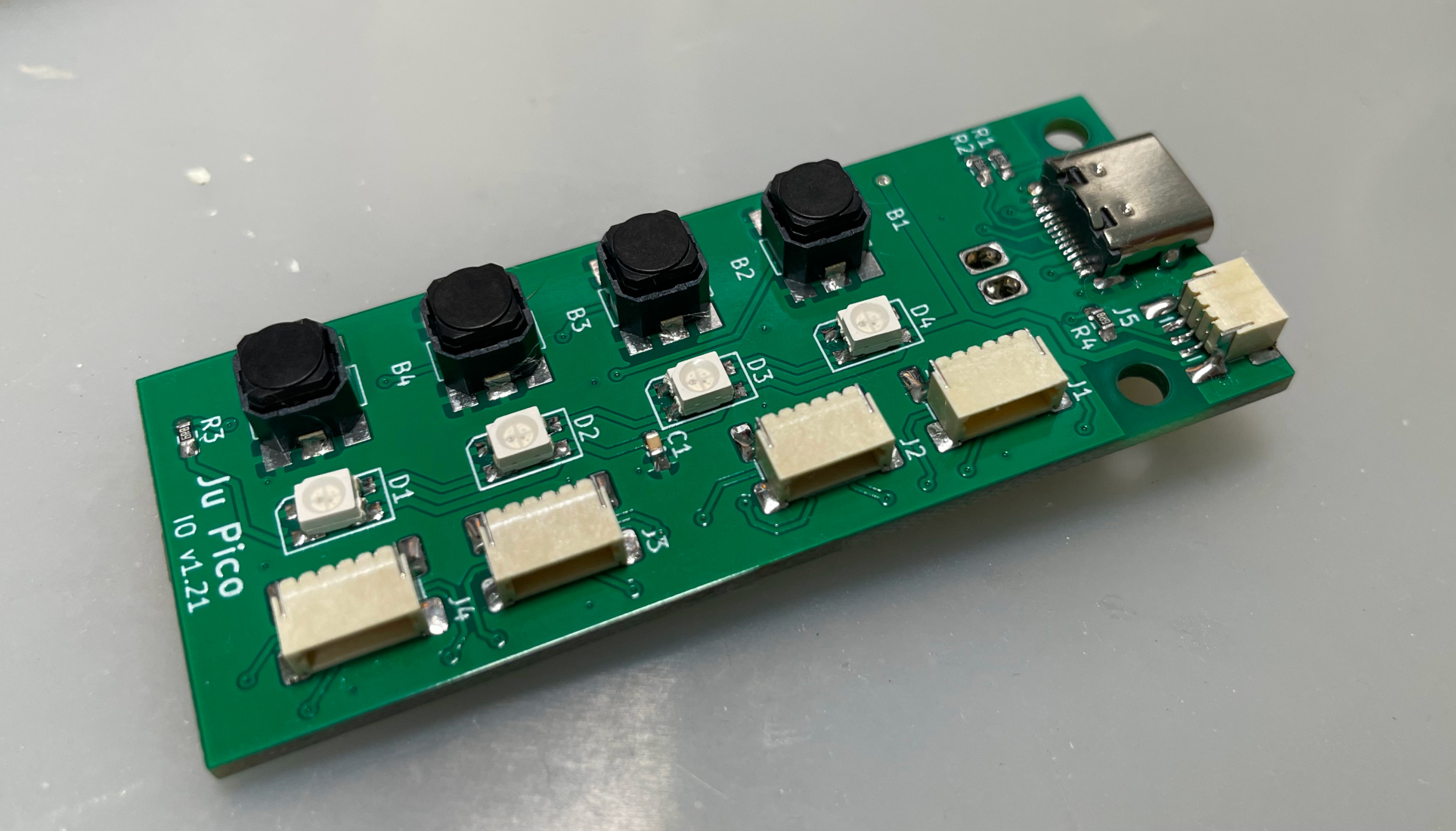
  • 1x Raspberry Pico Pi Pico or pin-to-pin compatible clones (U1).
    https://www.raspberrypi.com/products/raspberry-pi-pico
  • 1x USB Type-C socket (918-418K2023S40001 or KH-TYPE-C-16P)
  • 4x WS2812B-3528 RGB LEDs.
  • 4x Alps SKPMAPE010 6.0×5.9mm tactile switch in black, Panasonic EVQP1K05M works too, but it only comes in a white version.
    https://tech.alpsalpine.com/e/products/detail/SKPMAPE010/
  • 1x 0603 0.1uF (0.1~1uF all fine) capacitor (C1).
  • 2x 0603 5.1kohm resistors (R1, R2) for the USB.
  • 8x JST-SH1.0 5-pin SMD connectors (J1 to J4 on IO PCB, and 4 others on button PCBs).
  • 1x JST-SH1.0 3-pin SMD connector (J5), optional for future HID light expansion.
  • 4x JST-SH1.0 dual-end 5-pin cables (pin 1 to pin 1 mapping): 2 cables of 20cm length, and 2 cables of 30cm length.
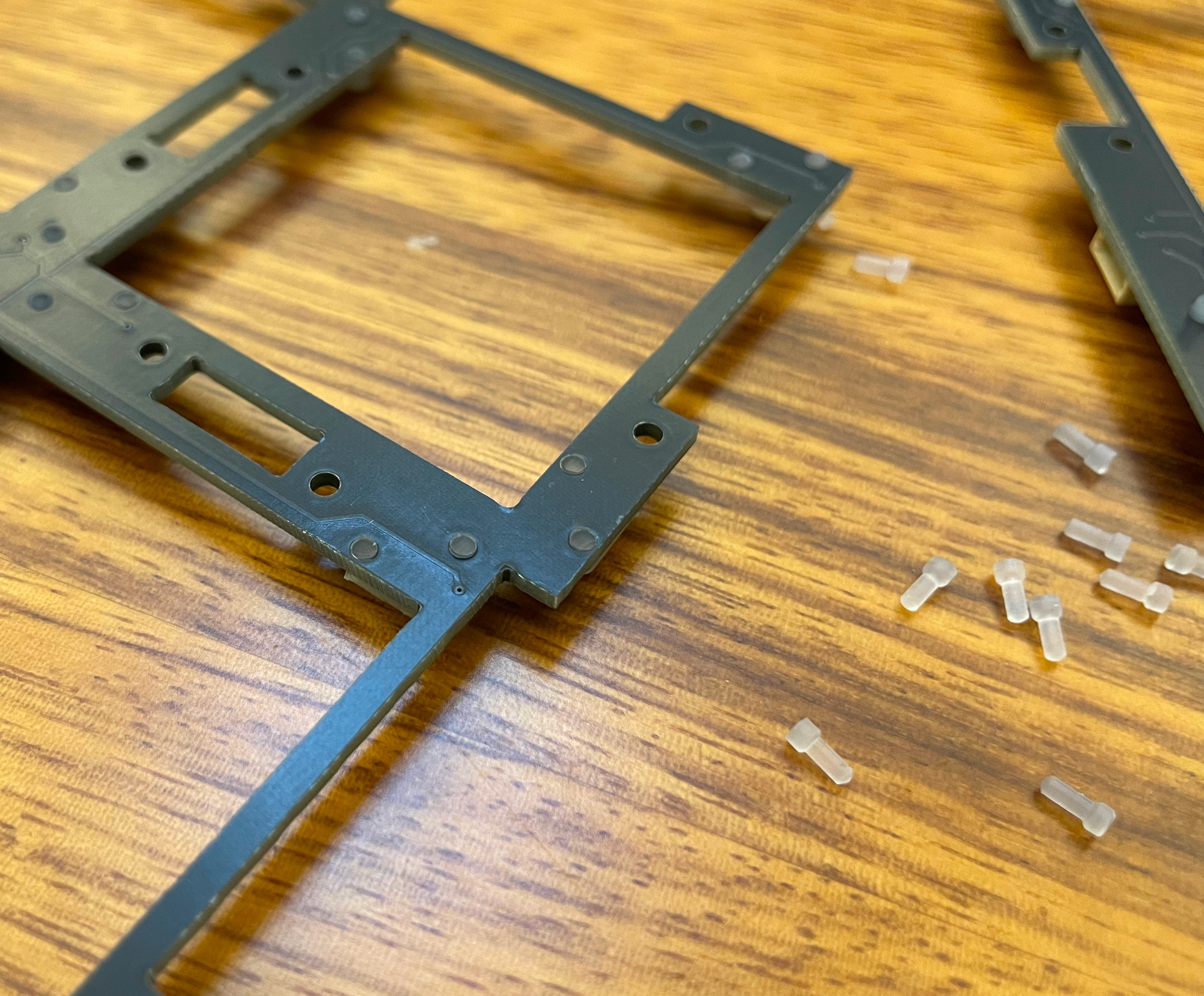
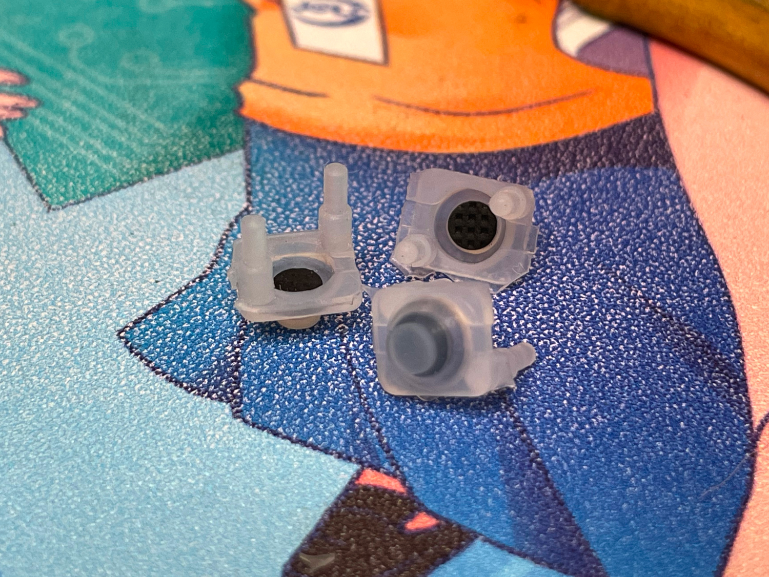
  • 64x Silicone rubber buttons, 6mm*7mm, 4mm height, with 2 legs. Buy soft (lower actuation force) ones if possible. It looks like this:
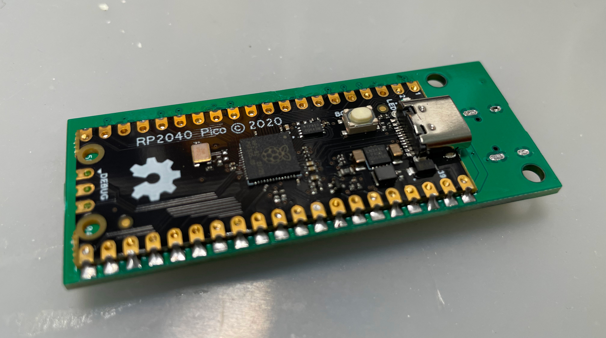
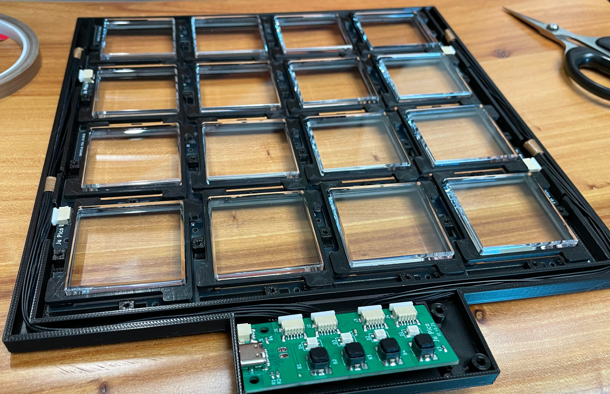
  • This is how the I/O board looks after soldering.

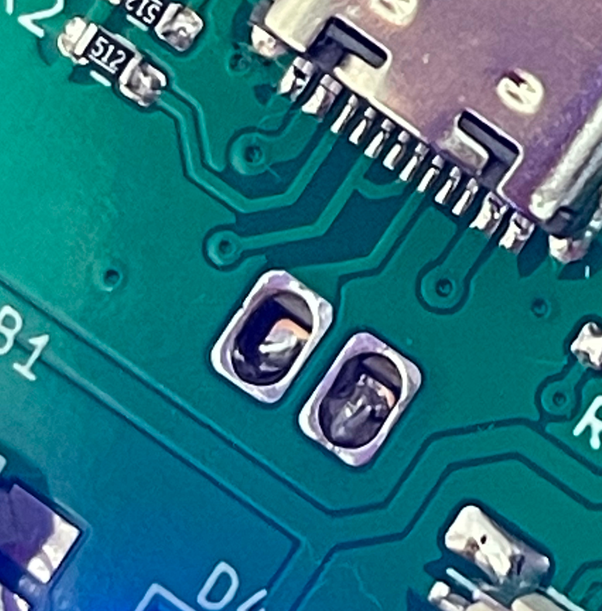
  • Becareful of 2 pin holes. It's a common oversight to either forget to solder them or to leave air bubbles during the process. To avoid this, solder slowly from one side of the hole, using minimal solder wire and a generous amount of flux.

Test the IO PCB

  • You can test the PCB now, put the firmware in IO PCB.
  • All 4 RGB LEDs should light up in a rainbow pattern.
  • LEDs responds to the the leftmost button, indicating current orientation.
  • Ju Pico should be recognized as a USB HID device, here's the test page.
    https://greggman.github.io/html5-gamepad-test/
  • Connect the 4 button PCBs to the IO PCB, and use one rubber button to test the button contacts on the PCB, you'll see the status change in said HID test page.

Button Cap

Ju Pico has 16 buttons, so you need to order 16 button caps.

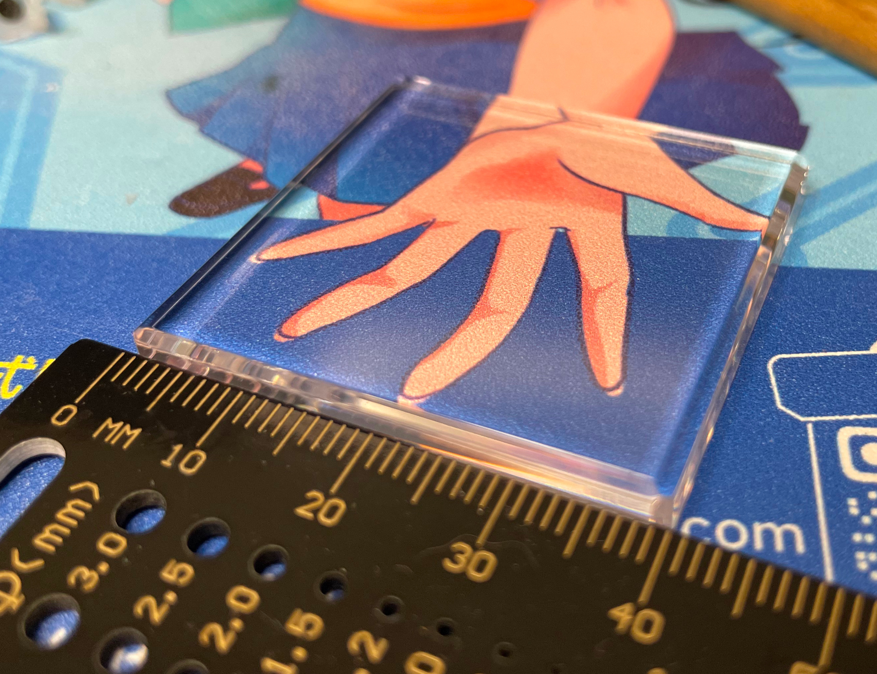
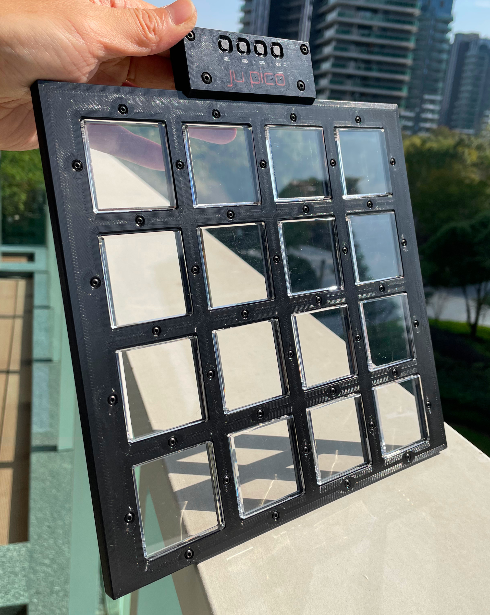
They are made of clear acrylic, measuring 40mm x 40mm with a corner radius of 1-1.5mm and a thickness of 5mm. All these parameters are IMPORTANT and should be followed closely. A polished bevel of 1.5-2mm on top edges gives a better feel.

Here's what it looks like.
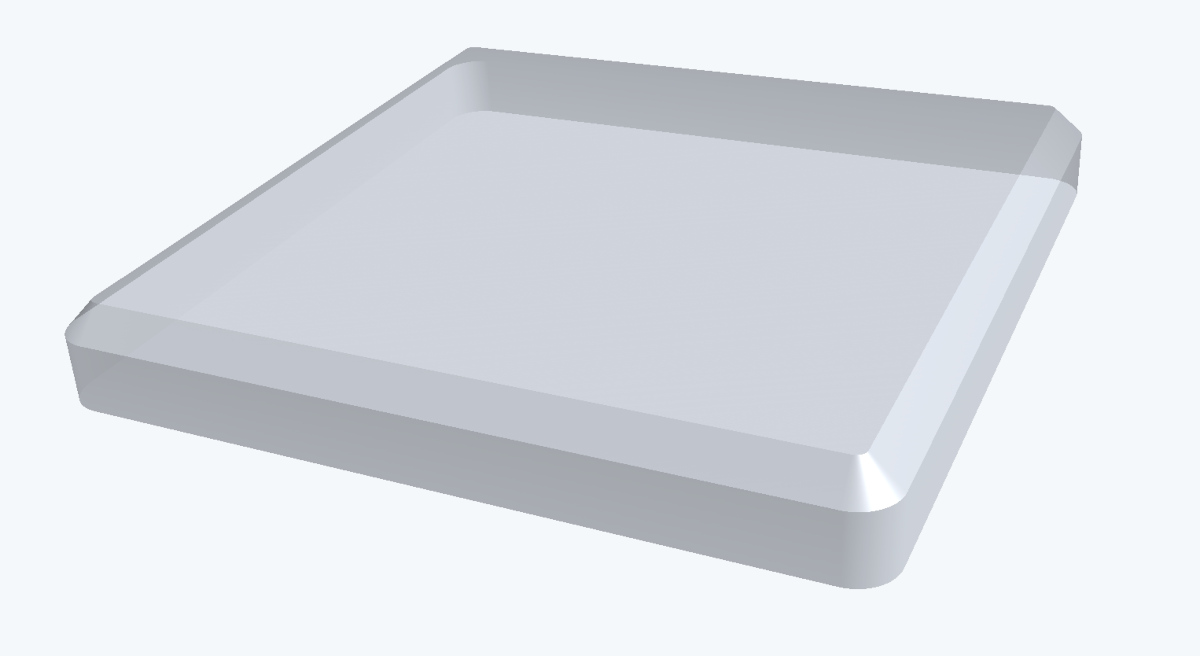
3D Printing

Printing parameters
  • PLA (recommended) or PETG.
  • Layer height: 0.2mm.
  • Walls: 5.
  • Infill: >=80%.
  • Support: Yes, better with special support material.
  • Glue on bed: Yes, it prevents corner warping.
  • Files are always in millimeter unit, not inch.
Parts
  • Note: if you want to build Ju Pico+, please use the files with "+" in the filename.
  • You have 3 options for the Frame part, heatset insert version is recommended.
    • Screws are threaded into heatset inserts: Production\3DPrint\ju_pico_frame_inserts.stl, black. Please install the heat-set inserts first.
    • Screws are directly threaded into the printed material: Production\3DPrint\ju_pico_frame.stl, black. Assembly is easier but the screws may wear out the material over time.
    • Screws are threaded into the hex nuts: Production\3DPrint\ju_pico_frame_hexnut.stl, black. Assembly is a bit more complicated but the screws won't wear out the material.
  • Panel: Production\3DPrint\ju_pico_panel.stl, black, print up-side-down with support (use special support material if possible).
  • Banner: Production\3DPrint\ju_pico_banner.3mf, multi-color, print up-side-down, mainbody is black, LED windows are transparent, logos are red or orange, use special support material if possible.
  • 16x Button Seats: Production\3DPrint\ju_pico_button_seat_*.stl, black, print up-side-down to avoid overhanging. Choose the one that fits your button cap.
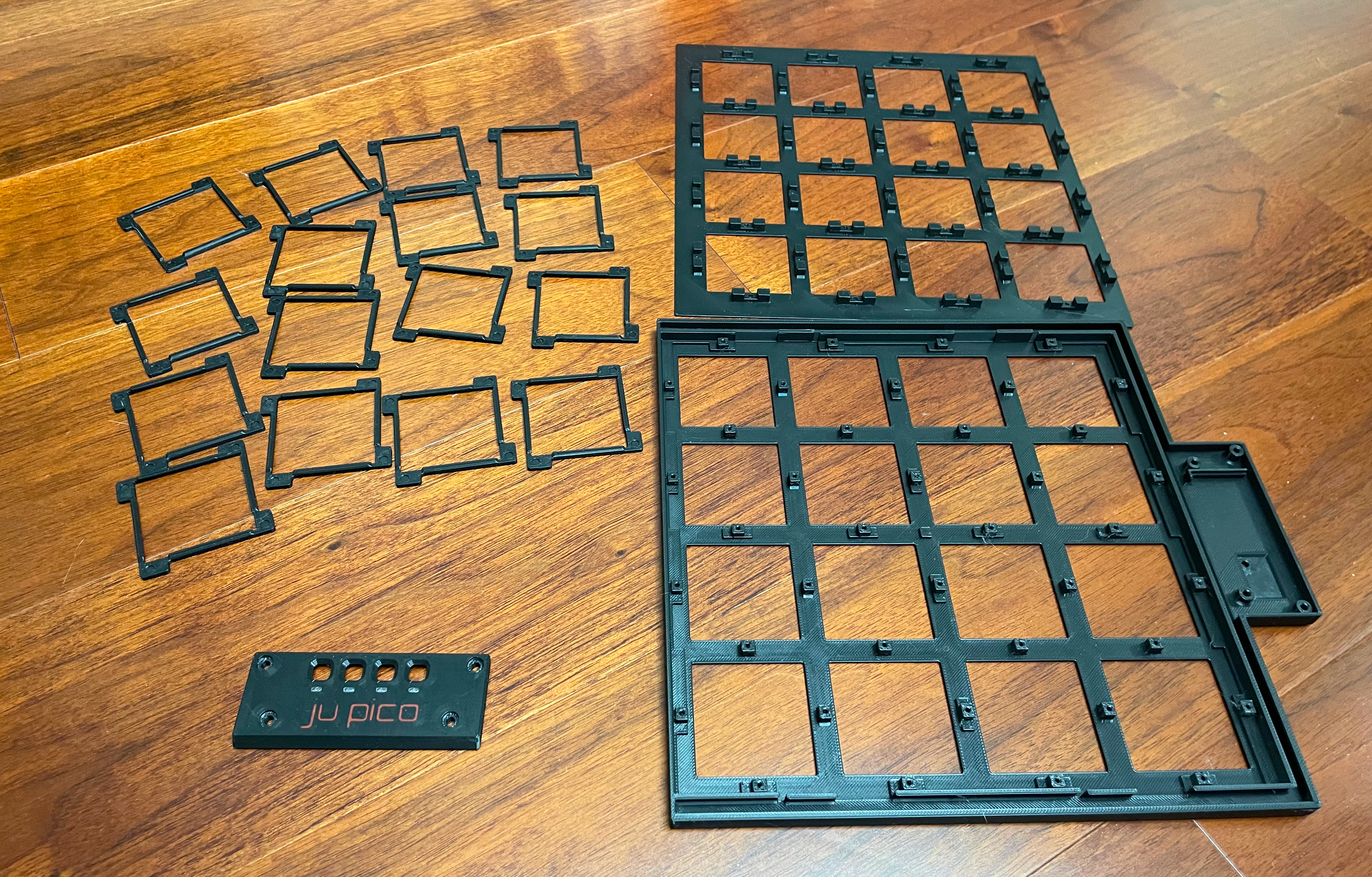
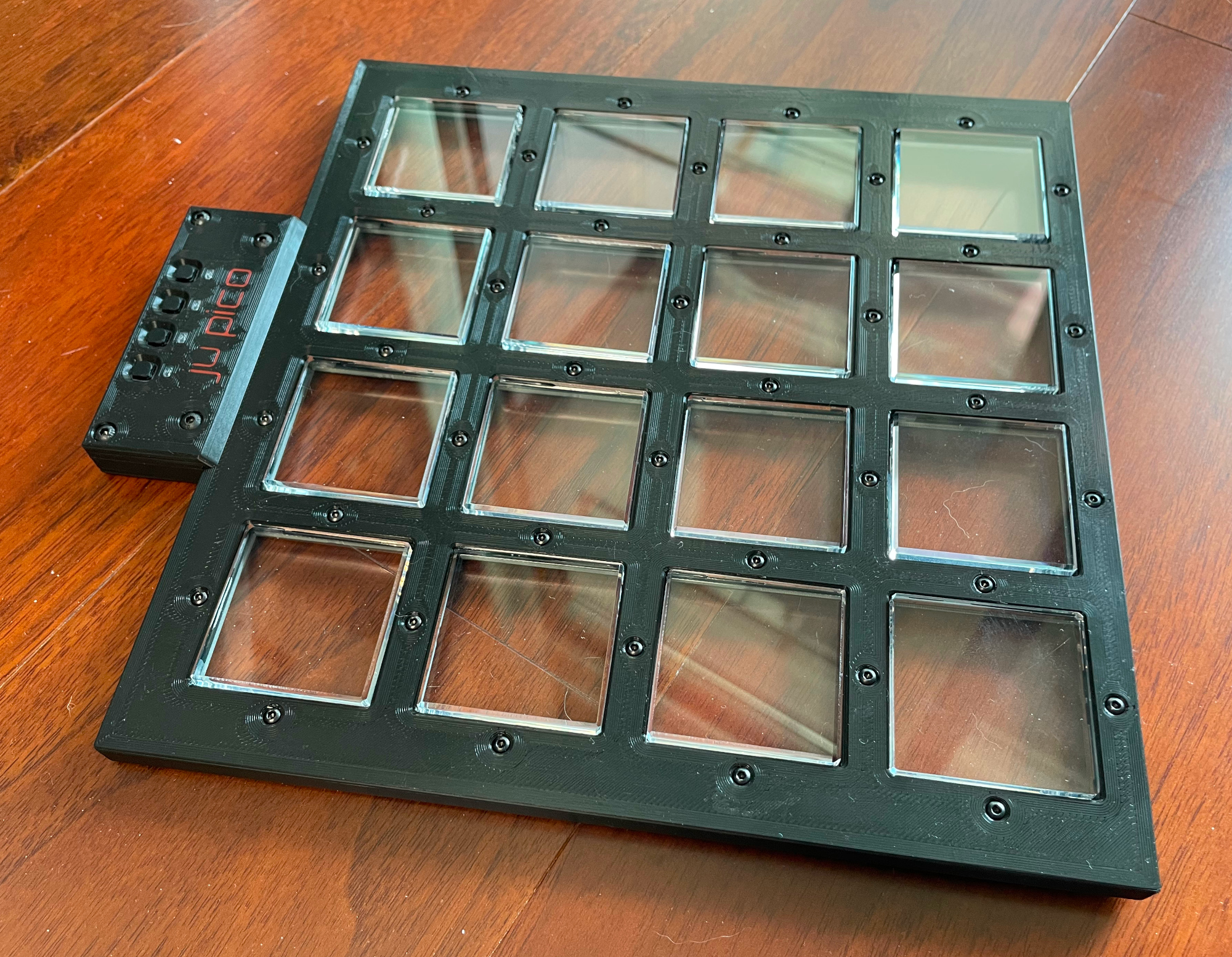
  • All together, they look like these.
  • Note: Files with "bambu" in the name are project files prepared for Bambu Studio.
  • CAUTION: Do not mix use files before and after December 2024, as I made some incompatible changes in early December 2024.

CNC Aluminum Processing (Optional, only available for Ju Pico)

  • If you're into that sleek metal look and don't mind splurging a bit, you can get the frame, panel, and banner parts CNC machined from aluminum.
  • Sandblasting and anodizing can be chosen to make it look even better.
  • The STEP files are in Production\CNC folder, the 2D DWG file is the thread tapping drawing for the frame part.
  • You need to 3D print Production\3DPrint\ju_pico_led_diffuser_for_cnc.stl for LED diffusion, use transparent material.
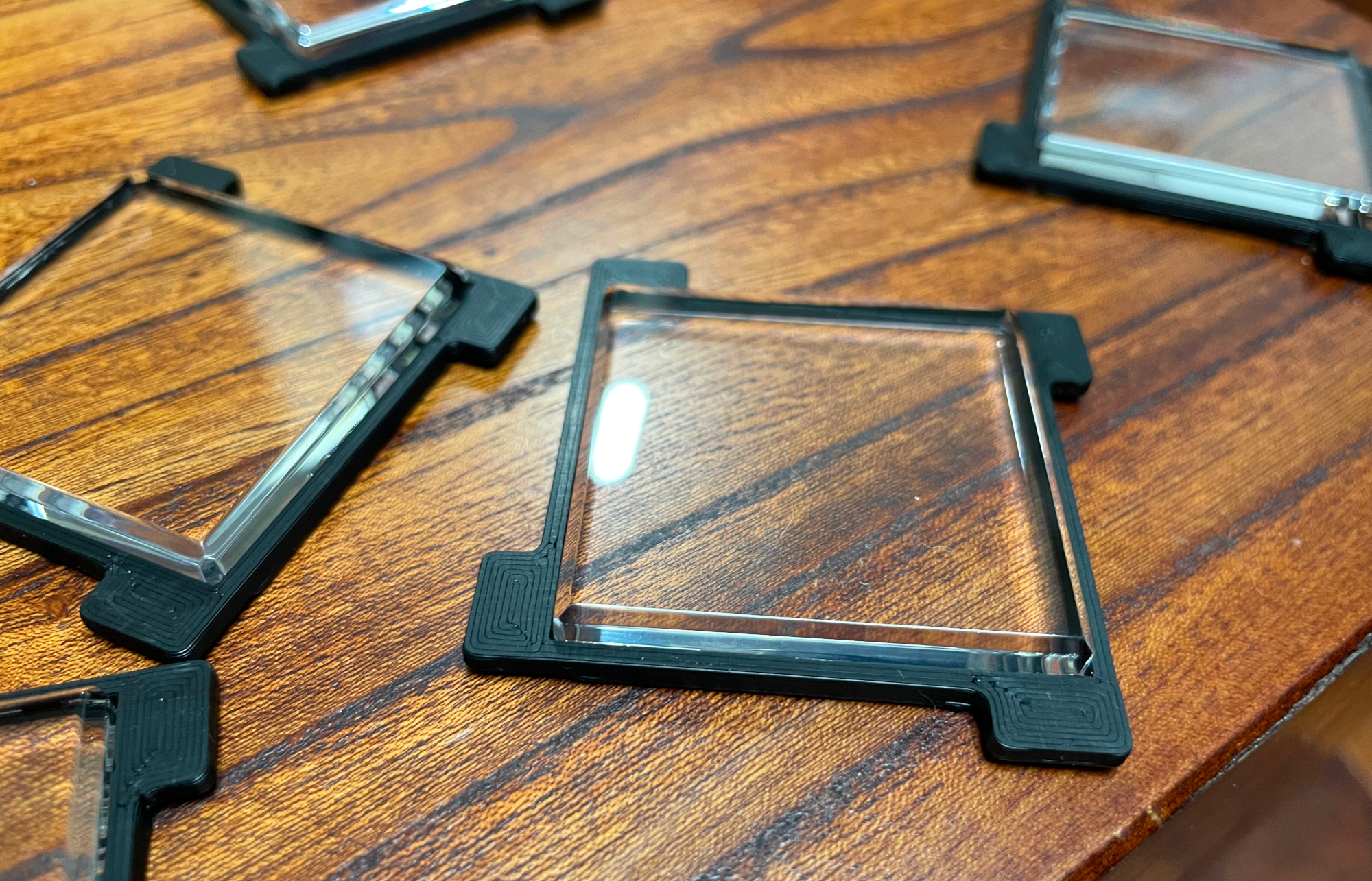
Assembly

Other Materials Needed
  1. Clear soft/flexible glue or UV curing glue. WARNING: Avoid using any cyanoacrylate-based glue, such as 502. Any glue with a similar smell should also be avoided, as they will leave white smoke marks on the acrylic.
  2. 40x M2*6mm (for regular frame) or M2*7mm (for hex nut frame or heatset insert frame) screws, black, for the panel.
  3. 4x M3*8mm screws, black, for the banner.
  4. 40x M2 hex nuts (only for hex nut frame version).
  5. 40x M2*3mm*3mm heat-set inserts (only for heatset insert frame version).

Step by Step

  1. Glue the button bodies to the button seats. Be careful don't let the glue ruin the acrylic. See the "Caution" section below for more details.
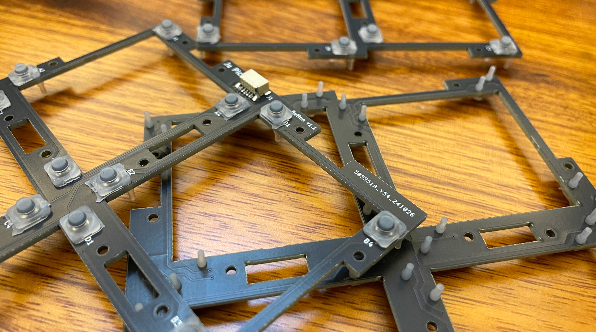
  2. Insert the silicone rubber buttons into the button PCBs. Ensure to pull the legs so that the button sits perfectly flush against the PCB.
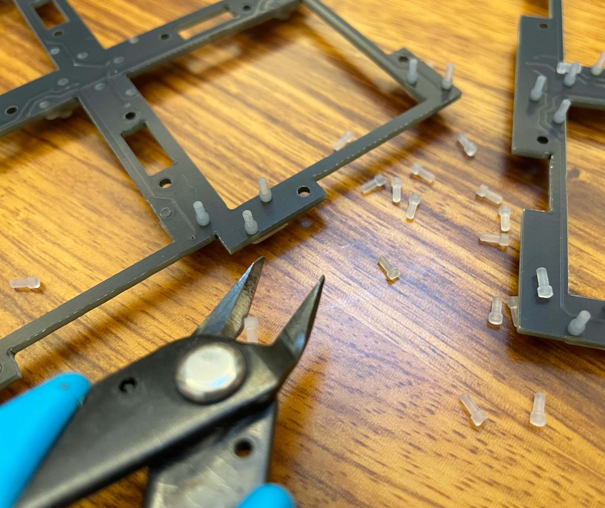
  3. Use a sharp side cutter to trim the legs of the rubber buttons so that they are flush with the PCB, leaving no protruding parts.
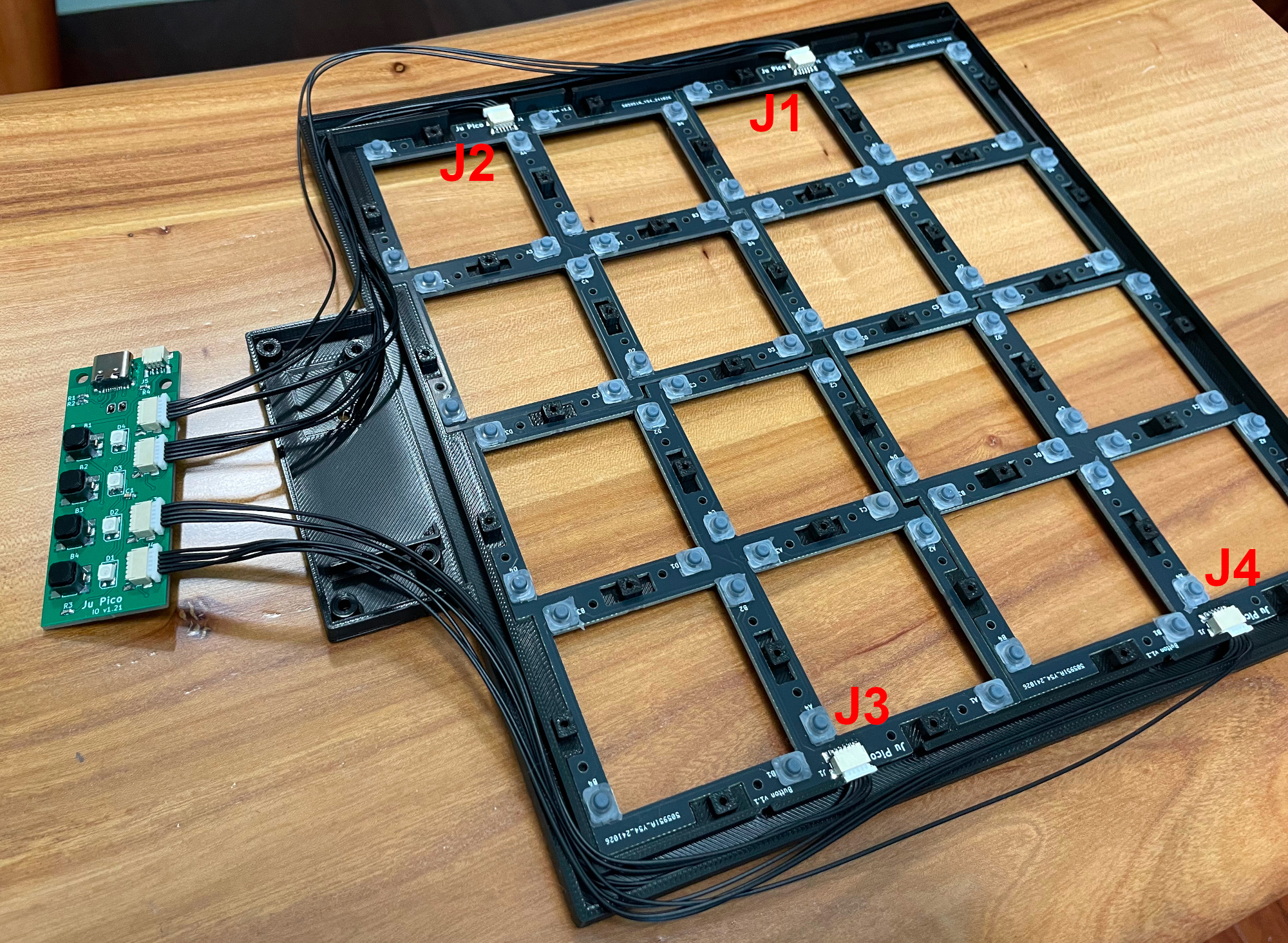
  4. Put button PCBs into the frame part and use the cables to connect them to the IO PCB.
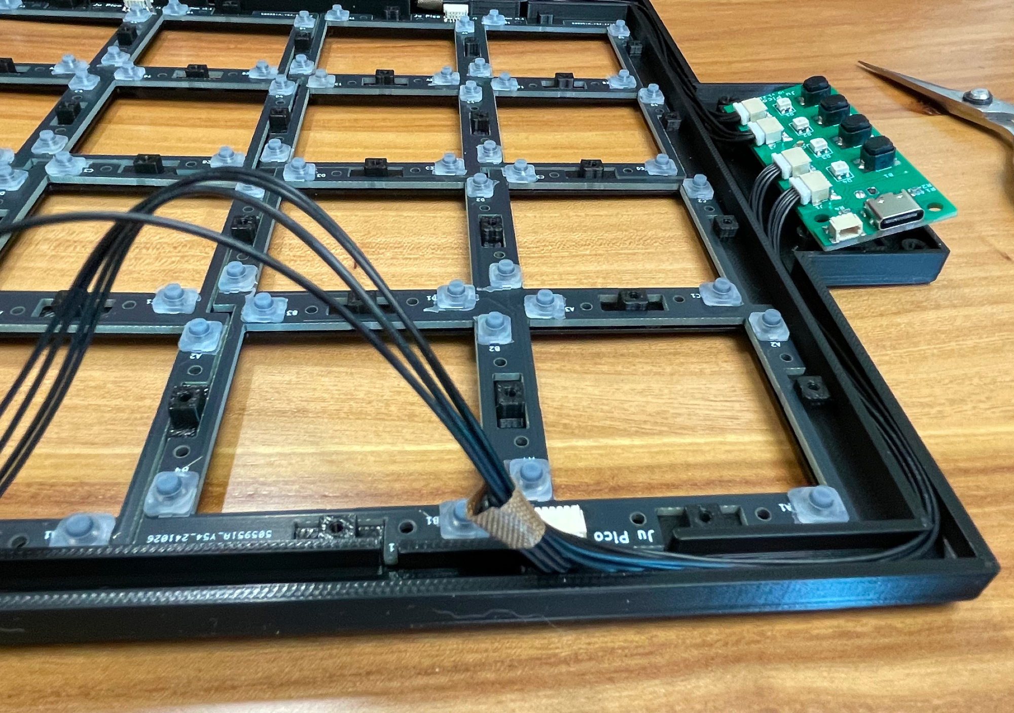
  5. Arrange the cables and make them fit in the cable slots.
  6. If you arrange them well, it will look very neat.
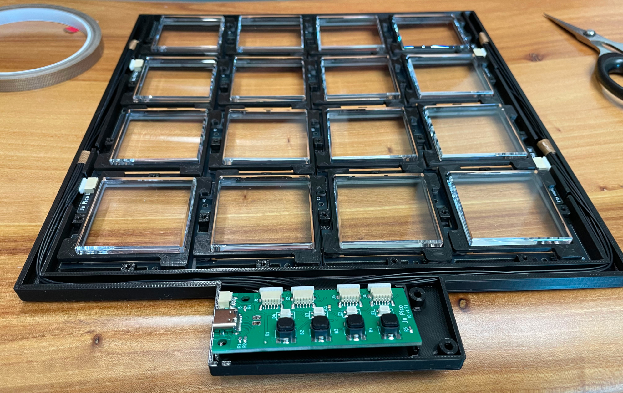
  7. Gently put the finished buttons onto the button PCBs.
  8. Attach the panel part and secure it with (a lot) M2 screws. Be very careful, 3D print materials are fragile and sensitive to heat. So screw slowly, especially when using a power screwdriver, as the threads in the plastic can easily strip. Lastly put on the banner part and use M3 screws to fix it. And there you go!
Caution

Each 3D printer and filament has its own tolerance, as does the acrylic cutting service. Therefore, I've created multiple versions of the button seat. You can try them and select the one that fits your acrylic button cap perfectly.

Firmware

  • UF2 file is in Production\Firmware folder.
  • For the new build, hold the BOOTSEL button while connect the USB to a PC, there will be a disk named "RPI-RP2" showed up. Drag the UF2 firmware binary file into it. That's it. There's a small hole at the bottom side of the Ju Pico, it is facing right to the BOOTSEL button.
  • If it's already running Ju Pico firmware, you can either use "update" in command line or hold down at least 4 buttons while connecting to USB to enter update mode.
  • To access the command line, you can use this Web Serial Terminal to connect to the USB serial port of the Ju Pico. (Note: "?" is for help)
    https://googlechromelabs.github.io/serial-terminal/

Usage

  • Attach the Ju Pico to a 15.6-inch portable monitor (or Ju Pico+ to a 21.5-inch monitor) using VHB residue-free adhesive tape. Use 3 to 4 small pieces on the monitor's frame, but avoid placing any on the screen. Position it in the orientation that best suits your needs.
  • Press the auxiliary button closest to letter 'j" of the logo "Ju Pico" together with the top left main button in the actual placement to set button order that matches your orientation. Analog joystick position in HID report indicates which side the logo should be. You can use the following website to see the joystick status.
    https://greggman.github.io/html5-gamepad-test/

CAD Source File

I'm using OnShape free subscription. It's powerful but it can't archive original designs to local, so I can only share the link here. STL/DXF/DWG files are exported from this online document.
https://cad.onshape.com/documents/c70fd7c4cb933fd28c4678b3/w/277dab41d8d592c817e9419a/e/e9cf38ee55134a09b2deb5d6

Parts

20
QtyValueFootprintReferences
4SW_SPSTju_touch:EVQP1K05MB1, B2, B3, B4
4WS2812B_Unifiedju_touch:WS2812B-2835D1, D2, D3, D4
30.1uFCapacitor_SMD:C_0603_1608Metric_Pad1.08x0.95mm_HandSolderC1, C2, C3
25K1Resistor_SMD:R_0603_1608Metric_Pad0.98x0.95mm_HandSolderR1, R2
2Conn_01x08_Socketju_touch:JuTouch_Conn8ITO1, ITO2
2MPR121QR2_BOARDju_touch:MPR121_BOARDU2, U3
110Resistor_SMD:R_0603_1608Metric_Pad0.98x0.95mm_HandSolderR3
1PiPico_No_SWDju_touch:RPi_Pico_SMD_Pins_No_SWD_No_TextU1
1U262-161N-4BVC11Type-C:HRO-TYPE-C-31-M-12-AssemblyUSB1

More from whowechina/ju_pico

2
  • 2 layers26 × 65 mmJu io, the printed circuit board in 3D

    Ju io

    whowechina/ju_pico

    Jubeat Style Controller

    18 parts23
  • 2 layers103.2 × 105.2 mmJu button, the printed circuit board in 3D

    Ju button

    whowechina/ju_pico

    Jubeat Style Controller

    17 parts23

Similar boards

  • 4 layers52 × 52 mmMoto gps rev a1, the printed circuit board in 3D

    Moto gps rev a1

    mx3353672833-debug/moto-gps-waveshare

    MOTO GPS · Waveshare ESP32-S3 1.75C 圆屏导航 + iPhone App | Author: Maler X | Noncommercial, attribution required | Experimental

    112 parts529
  • 2 layers98 × 80 mmMai io, the printed circuit board in 3D

    Mai io

    whowechina/mai_pico

    Pico controller for Maimai

    42 parts475
  • 2 layers294 × 100 mmChu main, the printed circuit board in 3D

    Chu main

    whowechina/chu_pico

    Pico controller for Chunithm-type rhythm game

    113 parts196
  • 2 layers35 × 40 mmFemto tester v1, the printed circuit board in 3D

    Femto tester v1

    mfolejewski/FEMTO

    FEMTO - RP2040 12x12mm PCB module

    78 parts159
  • 2 layers180 × 160 mmIidx pico, the printed circuit board in 3D

    Iidx pico

    whowechina/iidx_pico

    Pico beatmania IIDX controller

    94 parts125
  • 4 layers38.4 × 128.5 mmPlantpal, the printed circuit board in 3D

    Plantpal

    teapotlaboratories/plantpal

    Your pal in plant care

    121 parts98MIT
  • 2 layers70 × 20 mmPicoBerry V1.0, the printed circuit board in 3D

    PicoBerry V1.0

    mfolejewski/PicoBerry

    PicoBerry - small CM4 carrier board with full 40-pin GPIO header

    36 parts63
  • 2 layers297 × 95 mmPop pico2, the printed circuit board in 3D

    Pop pico2

    whowechina/popn_pico

    Pop'n Music Pico Controller

    57 parts57

Questions

How big is the Ju touch PCB?

It measures 160 × 24 mm and has 2 copper layers, 1.6 mm thick.

What parts does the Ju touch use?

20 parts, built around the U262-161N-4BVC11. The full list of its parts is on this page, with links to each part's symbol and footprint where PCBKit's library has them.

Where can I download the Ju touch KiCad files?

From the whowechina/ju_pico repository on GitHub, at the commit this page was made from: the board is PCB/Touch/ju_touch.kicad_pcb and its schematic PCB/Button/ju_button.kicad_sch. PCBKit opens the board in the browser, with nothing to install.

Can I use the Ju touch design in my own project?

Its repository states no licence, so its author keeps all rights: ask whowechina before reusing the design.