2 layers60 × 40 mm
 wgbowley/OpenLSM11
Low-Cost Linear Synchronous Permanent-Magnet Motor
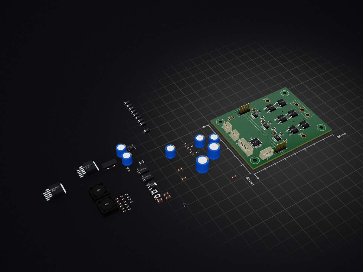
01 main is an open-source printed circuit board by wgbowley, from the wgbowley/OpenLSM repository on GitHub, published under the MIT licence. It is a 4-layer board of 80 × 60 mm with 99 parts on 82 nets, routed with 64 tracks and 7 vias.
It is built around the CME0303S3C, CME0512S3C and MAX3485ED, with the IRS2104PBF, AMC1311DWV and LM2596S-12 among its other parts. Its parts include 28 capacitors, 21 resistors, 16 ICs, 12 diodes and 6 transistors. It belongs with the robots and motor control boards and the STM32 boards of this library.



Low-Cost Linear Synchronous Permanent-Magnet Motor
OpenLSM is an open-source project to design low-cost linear motors for 3D printers and related Cartesian motion systems.
The project intends to require only limited tooling, specifically a lathe (and supporting tools), soldering equipment, a 3D printer, and a lot of patience.
Ultimately, the project will conclude by establishing a reference design that is intended to be extended upon by the community.
- [x] Support voltage bus ranges of `12 V_dc` and `24 V_dc`.
- [x] Validate the TeensySFOC, armature board and encoder board for linear motor applications.
- [x] Total BOM cost for the motor (armature + stator) under $100 AUS.
- [/] Achieve a target force per amp of `3.0-15 N/A_rms` and positional accuracy of `1.96-50 µm`.
- [/] Reach an asymptote temperature of `60°C` under constant `5-10 N` static loading.
- [/] Validate motor performance (100h+) and generate performance curves for each voltage range.
- [/] Scope a `Prototype Gamma` as an entry point for contributors to extend beyond OpenLSM.
(Note).
[/]In progress.[x]Complete.
(Ordered). The radial heat-sink, potting material, and interface PCB have been ordered.
An ironless tubular linear motor featuring a passive radial 6061 anodized heat sink potted around the enameled copper slots. Due to the low electrical frequency of ~65 Hz at a linear velocity of 650 mm/s, eddy currents are a second-order effect compared to removing heat from the slots. The armature has 18 slots of 0.3 mm diameter enamelled wire, with 6 slots in series per phase. The stator is a carbon fibre tube with 10 mm × 10 mm N52 poles arranged as (N-S|S-N). The motor is intended to be used with 12–24 V supplies.
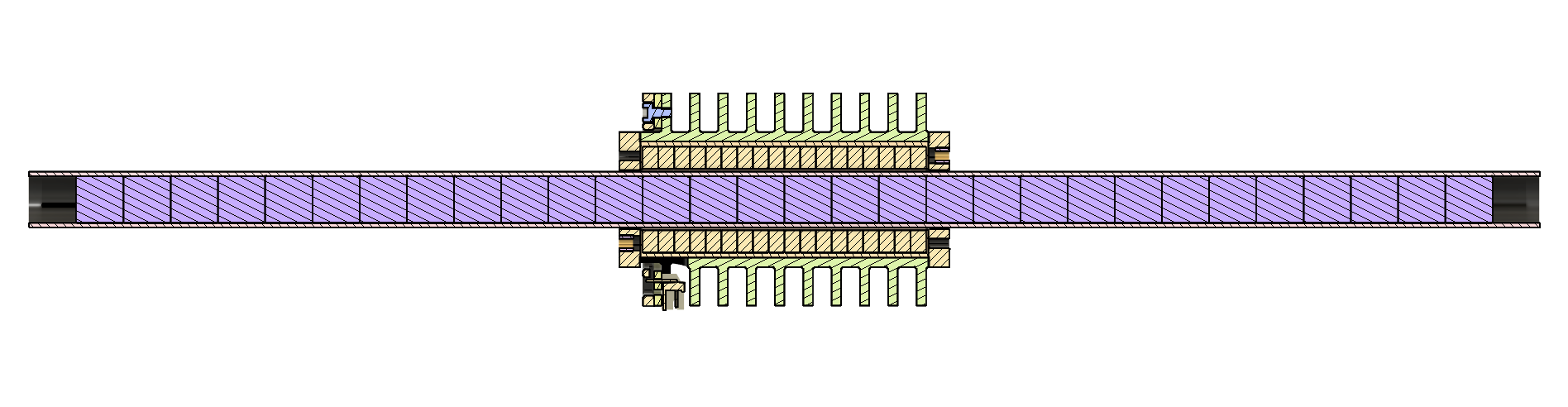
Cross-sectional analysis of armature & stator (Click image for fusion 360 webview.)
See design notes for more details.
This analytical model uses control currents (id, iq) and then a three-phase transform to compute the phase current based on position,
then uses 1D field approximations to compute the magnetic co-energy, and finally uses its spatial derivative over the z-axis to compute force.
This is then repeated across the stator to produce a force vs position graph.
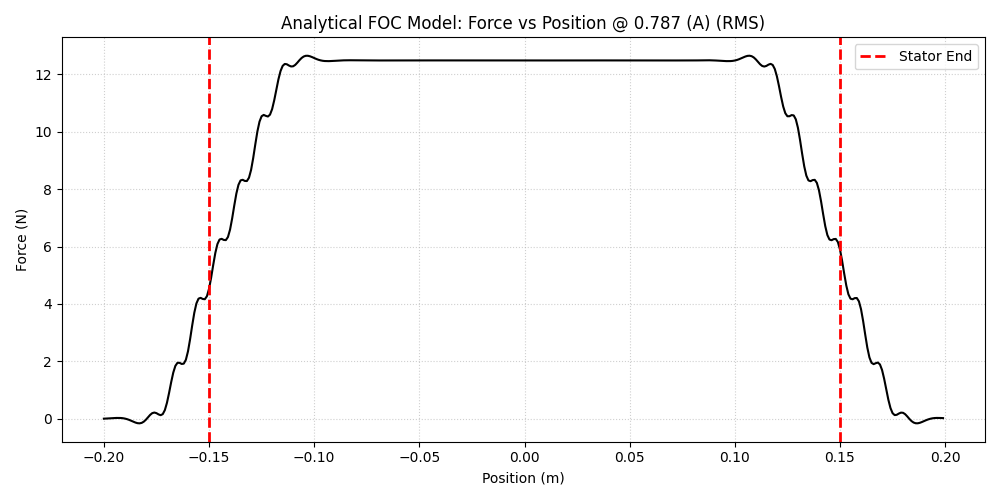
1D field approximation and FOC showing position (linear) vs force (linear).
See ../00_magnetic for more details.
This analytical model uses heat conduction to model the temperature drop across the potting material and heat sink base. It then uses the surface temperature of the exposed heat sink to calculate the conductive, convective and radiate heat dissipation of a specific geometry. It then repeats this across a grid of fin spacing and radial fin sizes to produce a thermal performance graph.
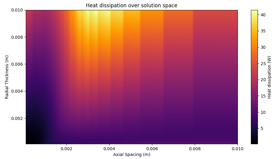
Grid search over fin axial spacing and outer diameter.
See ../01_thermal for more details.
The integrated sensor boards are a platform for measuring the motor's position, acceleration, and thermal profile T(z, t).
The system consists of two boards: an encoder board with a resolution of 1.96 µm and estimated accuracy of 10–20 µm,
and a sensor board featuring a thermistor array, 3-axis SPI accelerometer, encoder interface, and RS-485/RS-422 output,
all collected via an STM32.
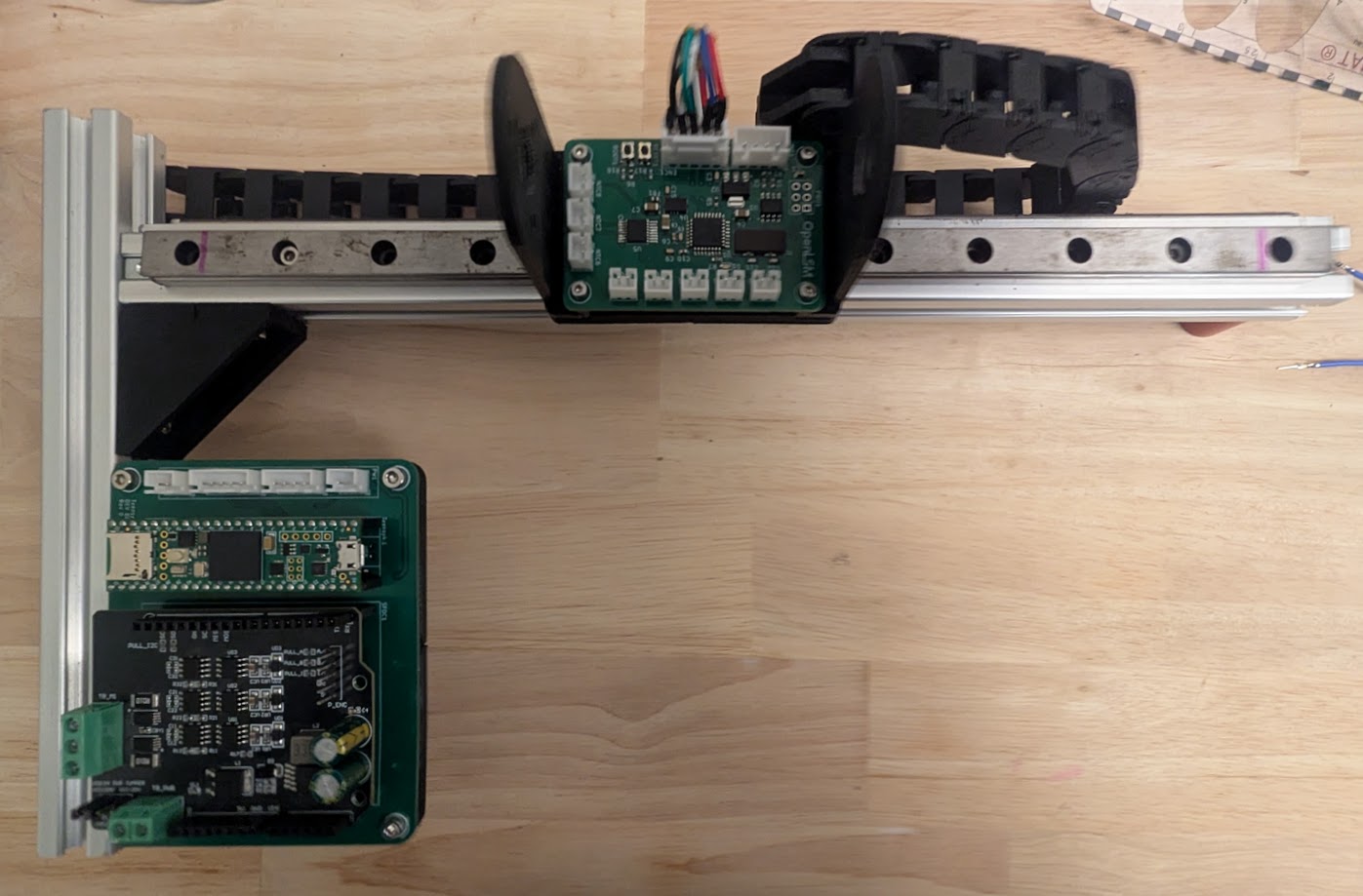
Validation stand with populated encoder and armature board.
The TeensySFOC board is a breakout board for the Teensy 4.1 and SimpleFOC Arduino shield with step/dir input.
It is a development board that is not intended for long-term usage.
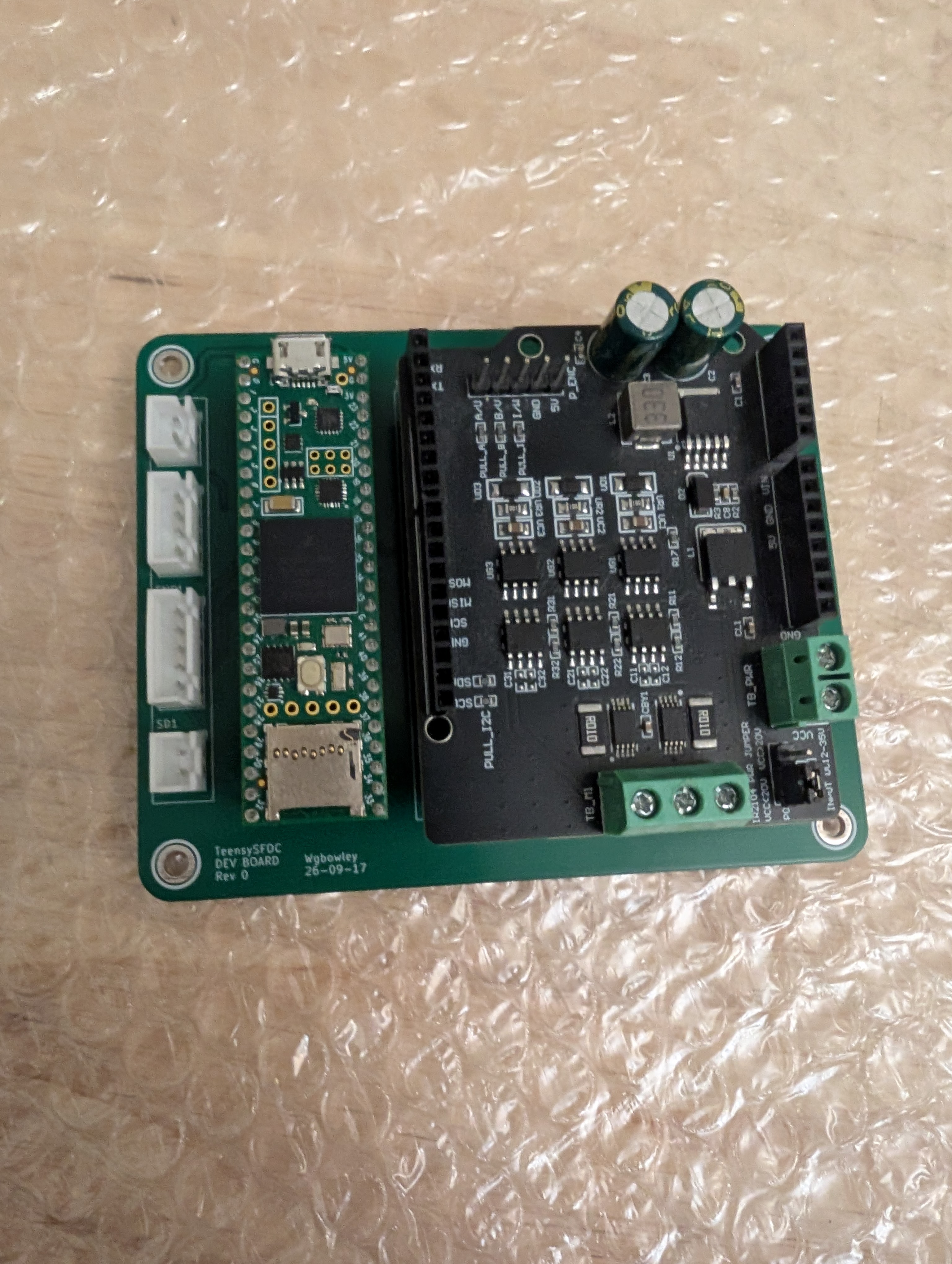
Populated TeensySFOC PCB.
For boards, see 03_boards.
For fixtures, see 04_fixtures.
An ironless planar linear motor with a polylactic acid (PLA) armature featuring 6 slots, hand wound using 0.2 mm diameter enameled copper wire and 5 mm wide Kapton tape, with 2 slots in-series per phase (WYE). The stator, similar to the armature, was printed in PLA and had 4 pole pairs per armature length and 10 pole pairs total. The motor produced measurable force, although the force output was not quantified before the PLA coil forms deformed due to thermal stress.
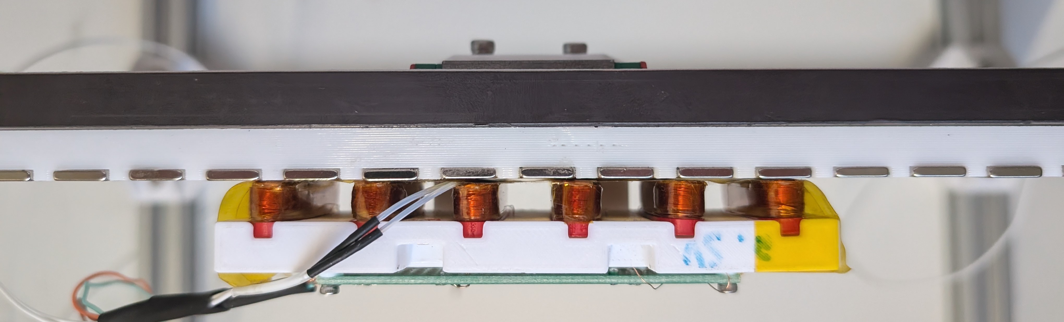
The main conclusion from Prototype Alpha is that planar linear motors likely require laminated silicon steel armatures to produce force efficiently. In response, Prototype Beta shifts to an ironless tubular topology with the goal of quantifying force output and thermal performance.
See the alpha notes for more details.
Each section of the repo is self-documenting.
For internal documentation, credits, and contributors, refer to 00_docs.
This folder contains items that were attempted but dropped, as they were determined to not serve the critical path of the project.
00 - 96 V, 30 A triple half-bridge driver.
01 - Hybrid model between FEMM and Biot–Savart
See 06_dropped for more details.
@misc{openLSM_2026,
  author = {William Bowley},
  title = {openLSM: Low-Cost Linear Synchronous Permanent-Magnet Motor},
  url = {https://github.com/wgbowley/openLSM},
  year = {2026},
  note = {GitHub repository},
  license = {MIT}
}| Qty | Value | Footprint | References |
|---|---|---|---|
| 9 | ES1D | ES1D:DIOM4325X250N | D1, D4, D5, D6, D9, D10, D11, D14, D15 |
| 6 | 47 | Resistor_SMD:R_1206_3216Metric | R2, R3, R5, R6, R8, R9 |
| 6 | SUD90330E | sud90330e:TO-252-2 | Q1, Q2, Q3, Q4, Q5, Q6 |
| 5 | 1uF | Capacitor_SMD:C_0603_1608Metric | C1, C4, C7, C10, C11 |
| 5 | 220uF | Capacitor_THT:CP_Radial_D8.0mm_P3.50mm | C3, C5, C8, C23, C25 |
| 4 | 100nf | Capacitor_SMD:C_0603_1608Metric | C14, C15, C17, C21 |
| 4 | 10uF | Capacitor_SMD:C_1206_3216Metric | C2, C6, C9, C28 |
| 3 | 220 | Resistor_SMD:R_0603_1608Metric | R14, R15, R18 |
| 3 | 5 | Resistor_SMD:R_0603_1608Metric | R1, R4, R7 |
| 3 | 5mOhm | Resistor_SMD:R_2512_6332Metric | R19, R20, R21 |
| 3 | IRS2104 | Package_SO:SOIC-8_3.9x4.9mm_P1.27mm | U1, U2, U3 |
| 2 | 01x02 | Connector_JST:JST_PH_B2B-PH-K_1x02_P2.00mm_Vertical | CAN1, STEP1 |
| 2 | 10 | Resistor_SMD:R_0603_1608Metric | R12, R13 |
| 2 | 10K | Resistor_SMD:R_0603_1608Metric | R16, R17 |
| 2 | 1N5824 | Diode_SMD:D_SMC | D17, D18 |
| 2 | 30pf | Capacitor_SMD:C_0603_1608Metric | C12, C13 |
| 2 | 680uF | Capacitor_THT:CP_Radial_D10.0mm_P5.00mm | C22, C24 |
| 2 | AMC1311 | AMC1311DWVR:DWV0008A | U12, U13 |
| 2 | Conn_01x01 | Connector_Wire:SolderWire-2.5sqmm_1x01_D2.4mm_OD3.6mm | PGND1, PVCC1 |
| 2 | INA241A2xD | Package_SO:SOIC-8_3.9x4.9mm_P1.27mm | U11, U16 |
| 2 | SW_Push | Button_Switch_SMD:SW_Push_1P1T_NO_CK_KMR2 | SW1, SW2 |
| 1 | 0.68uF | Capacitor_SMD:C_1206_3216Metric | C26 |
| 1 | 01x02 | Connector_Wire:SolderWire-0.5sqmm_1x02_P4.6mm_D0.9mm_OD2.1mm | VCC1 |
| 1 | 01x03 | Connector_Wire:SolderWire-2.5sqmm_1x03_P7.2mm_D2.4mm_OD3.6mm | PH1 |
| 1 | 01x04 | Connector_JST:JST_PH_B4B-PH-K_1x04_P2.00mm_Vertical | INT1 |
| 1 | 01x06 | Connector_JST:JST_PH_B6B-PH-K_1x06_P2.00mm_Vertical | PRO1 |
| 1 | 10uf | Capacitor_SMD:C_1206_3216Metric | C19 |
| 1 | 10uf | Capacitor_SMD:C_0603_1608Metric | C16 |
| 1 | 120 | Resistor_SMD:R_0603_1608Metric | R11 |
| 1 | 1uf | Capacitor_SMD:C_0603_1608Metric | C18 |
| 1 | 22uf | Capacitor_SMD:C_1206_3216Metric | C20 |
| 1 | 33uH | Inductor_SMD:L_Bourns_SRR1260 | L1 |
| 1 | 4.7k | Resistor_SMD:R_0603_1608Metric | R10 |
| 1 | 4.7uF | Capacitor_SMD:C_1206_3216Metric | C27 |
| 1 | 68uH | Inductor_SMD:L_Bourns_SRR1260 | L2 |
| 1 | 82103C | 82103C:IND_8200_MUR | L4 |
| 1 | 82683C | 82683C:FUSE_MF-USMFLAB | L3 |
| 1 | BLM18AG601SN1D | BLM18AG601SN1D:BEADC1608X95N | FB1 |
| 1 | CME0303S3C | CME0512S3C:CME_SC_MUR | U15 |
| 1 | CME0512S3C | CME0512S3C:CME_SC_MUR | U14 |
| 1 | ECS-80-20-18-TR | ECS-80-18-23B-JTN-TR:XTAL_ECS-80-20-18-TR | Y1 |
| 1 | ISO7740DWR | ISO7740DWR:SOIC127P1030X265-16N | U4 |
| 1 | LD1117V33 | Package_TO_SOT_SMD:SOT-223 | U7 |
| 1 | LED | LED_SMD:LED_0603_1608Metric_Pad1.05x0.95mm_HandSolder | D16 |
| 1 | LM2596S-12 | Package_TO_SOT_SMD:TO-263-5_TabPin3 | U9 |
| 1 | LM2596S-5 | Package_TO_SOT_SMD:TO-263-5_TabPin3 | U8 |
| 1 | MAX3485 | Package_SO:SOIC-8_3.9x4.9mm_P1.27mm | U6 |
| 1 | REF3020 | Package_TO_SOT_SMD:SOT-23 | U10 |
| 1 | STM32G431K8Tx | Package_QFP:LQFP-32_7x7mm_P0.8mm | U5 |


rhysyim/Electronic-Speed-Controller
Electronic Speed Controller of Brushless DC Motor

btanqy/LLC-GaN-Protoboard
This board will be a prototype GaN based LLC converter, with a target rating of 80W with 24V input to 400V output, ideally for renewable power conversion and high voltage applications in plasma generation.


mitmedialab/generic-pan-tilt-pcb
Generic Pan Tilt PCB sources

Thinkpad4by3/chibitron
Electrostatic CRT driver designed from the ground up for performance, versatility and ease-of-manufacturability

antmicro/cm4-baseboard-lvds-adapter
Adapter board converting MIPI DSI into LVDS with additional circuitry for integrating custom displays

atomspring/Moto-Turn-signals
Enhances old motorcycle visibility by running turn signals at low current until needed. LED & Incandescent compatible.

It measures 80 × 60 mm and has 4 copper layers, 1.6 mm thick.
99 parts, built around the CME0303S3C, CME0512S3C, MAX3485ED and IRS2104PBF. The full list of its parts is on this page, with links to each part's symbol and footprint where PCBKit's library has them.
From the wgbowley/OpenLSM repository on GitHub, at the commit this page was made from: the board is 06_dropped/00_bridge_driver/03_kicad/01_main/main.kicad_pcb and its schematic 02_motors/01_prototype_beta/rev_3/04_electrical/03_kicad/main.kicad_sch. PCBKit opens the board in the browser, with nothing to install.
Its repository publishes it under the MIT licence: you may reuse it on that licence's terms (keep the author's notice, and for a copyleft licence share your changes alike).