4 layers24 × 44 mm

 visionspacetec/VST104-Foxtrot5
VST104 Flat-Sat board - referred as element_foxtrot
Element foxtrot is an open-source printed circuit board by visionspacetec, from the visionspacetec/VST104-Foxtrot repository on GitHub. It is a 4-layer board of 202.5 × 307.5 mm with 147 parts on 221 nets, routed with 2,698 tracks and 697 vias.
It is built around the L7985, USBLC6-4 and TL432AIDBZR-TP, with the SQD40061EL_GE3, 2N7002BK and DDZ15CSF among its other parts. Its parts include 31 resistors, 22 capacitors, 18 diodes, 10 transistors and 9 connectors.


This repository contains the KiCad project and other documents created during the development of Element Foxtrot under VST104 project. This FlatSat board is capable of hosting four PC104 format modules with LibreCube PC104 header pinout.
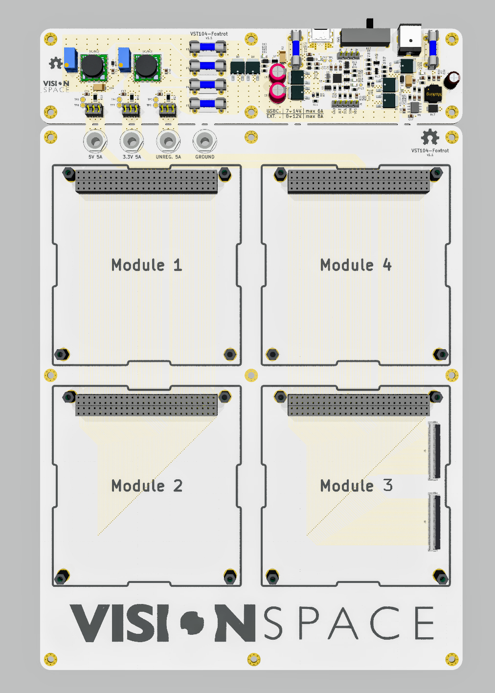
Fig 1. Element Foxtrot 3D visualisation.
modules: This flatsat board can accommodate up to four PC104 modules. The position and orientation of these slots are marked with silkscreen contours. Headers of the separate slots are connected in between each other concerning individual pins. Tracing of power lines is strengthened, and the ground is shared with the rest of the board.power circuitry: Upper part of the board carries power distribution circuitry. Power outputs of this part are connected to corresponding powerlines of PC104 slots. The usual setup is: 3.3[V], 5[V] and unregulated - individually rated to deliver up to 5[A] (depends on power source) to these power lines. Although different voltages in the regulated powerlines can be set by trimmers.power modes: A user can power this flatsat in two different modes. External power supply with standard 2[mm] JACK or USB-C charger. A three-position slide switch (on/off/on) placed between these two connectors is used to select one or none of them. Both of the modes are rated for input voltage in range 7-14[V] and input current up to 8[A] for JACK mode and 6[A] for USB-C mode.disconnection terminal: A set of removable jumpers is used to temporarily separate the power distribution circuitry from the rest of the flatsat. This is practical if a user needs to power the board from a different source or do not power it at all but is keen on not separating the power delivery circuitry by braking.4[mm] banana: After the disconnection terminal, just on the slots beginning, powerlines are placed a set of laboratory 2[mm] banana jacks. A user can use these jacks after disconnecting the corresponding terminals to point to any power or measuring device.
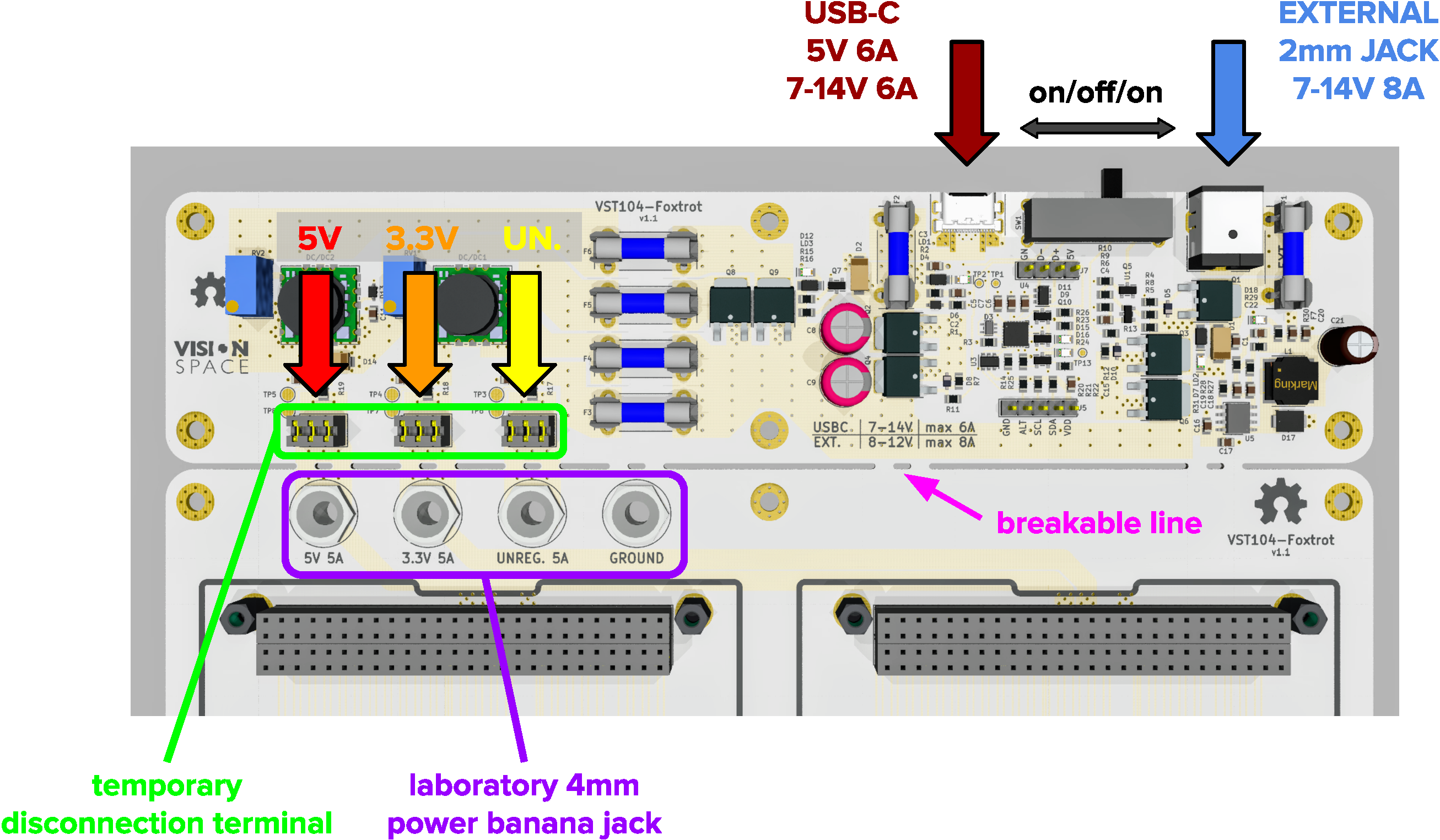
Fig 1. Graphical interpretation of segments described in "basic specifications" section.
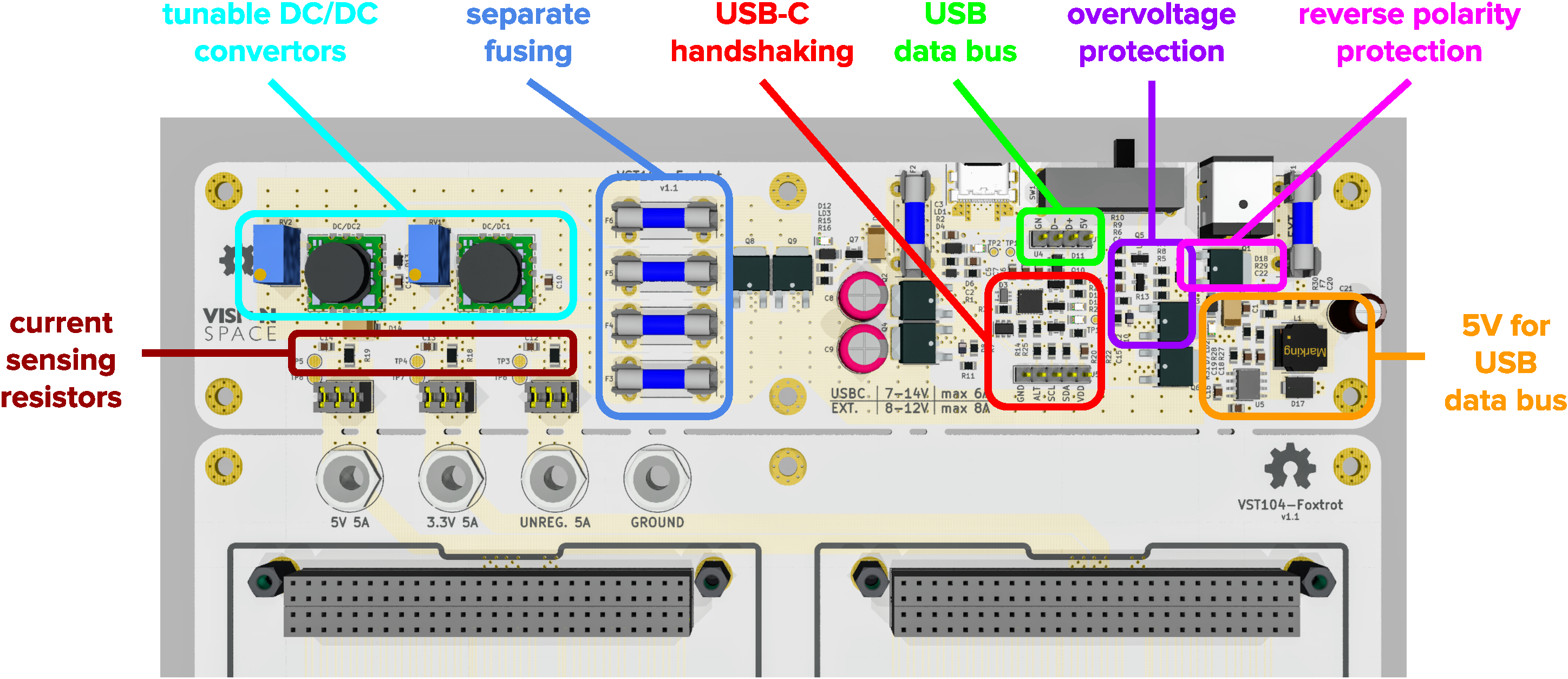
Fig 1. Graphical interpretation of segments described in "features" section.
| Qty | Value | Footprint | References |
|---|---|---|---|
| 15 | MountingHole_Pad | VST104_footprints:MountingHole_3.2mm_M3_Pad_Via | H1, H2, H3, H4, H5, H6, H7, H8, H9, H10, H11, H12, H13, H14, H15 |
| 9 | 100k | VST104_footprints:R_SMD_0805 | R3, R7, R9, R10, R12, R15, R16, R24, R25 |
| 7 | SQD40061EL | VST104_footprints:TO-252AA_6.5x6.1mm | Q1, Q2, Q3, Q4, Q6, Q8, Q9 |
| 6 | TestPoint_Alt | VST104_footprints:scope_PAD_2mm | TP3, TP4, TP5, TP6, TP7, TP8 |
| 5 | 10u | VST104_footprints:C_SMD_0805 | C12, C13, C14, C16, C20 |
| 5 | 1u | VST104_footprints:C_SMD_0805 | C2, C5, C6, C7, C15 |
| 4 | 10k | VST104_footprints:R_SMD_0805 | R4, R20, R21, R22 |
| 4 | 5A | VST104_footprints:FUSE_2AG_01110501Z | F3, F4, F5, F6 |
| 4 | PC104_module | VST104_footprints:PC104_footprint | Module_1, Module_2, Module_3, Module_4 |
| 4 | TestPoint_Alt | VST104_footprints:KSE_PN6095 | TP9, TP10, TP11, TP12 |
| 3 | 0 | VST104_footprints:R_SMD_1206 | R17, R18, R19 |
| 3 | 1k | VST104_footprints:R_SMD_0805 | R1, R14, R27 |
| 3 | 2N7002BK | VST104_footprints:SOT-23-3_2.9x1.3mm | Q5, Q7, Q10 |
| 3 | AL5809 | VST104_footprints:Power-DI-123_2.8x1.8x1mm | LD1, LD2, LD3 |
| 3 | DDZ15CSF | VST104_footprints:D_SOD-323-F_1.25x1.7mm | D5, D8, D10 |
| 3 | TestPoint | VST104_footprints:scope_PAD_1mm | TP1, TP2, TP13 |
| 3 | Val** | VST104_footprints:TSW-103-07-x-D | J2, J3, J4 |
| 2 | 100 | VST104_footprints:R_SMD_0805 | R26, R28 |
| 2 | 10A | VST104_footprints:FUSE_2AG_01110501Z | F1, F2 |
| 2 | 150 | VST104_footprints:R_SMD_0805 | R23, R30 |
| 2 | 1n | VST104_footprints:C_SMD_0805 | C4, C19 |
| 2 | 22k | VST104_footprints:R_SMD_0805 | R11, R13 |
| 2 | 22u | VST104_footprints:C_SMD_0805 | C10, C11 |
| 2 | 3k3 | VST104_footprints:trimer_3296W_10.0x9.5x10.0 | RV1, RV2 |
| 2 | 470u | VST104_footprints:CP_Radial_D8.0mm_P3.50mm_L11.5mm | C8, C9 |
| 2 | BAV199 | VST104_footprints:SOT-23-3_2.9x1.3mm | D9, D11 |
| 2 | Conn_01x45 | VST104_footprints:conn_FPC_45x0.5_505110-4591 | J6, J8 |
| 2 | SMAJ15CA | VST104_footprints:D_SMA_DO-214AC_4.3x2.6mm | D1, D2 |
| 2 | USBLC6-4 | VST104_footprints:SOT-23-6L_2.9x1.6mm | U3, U4 |
| 2 | Val** | VST104_footprints:OKL-T6-W12 | DC/DC1, DC/DC2 |
| 2 | green | VST104_footprints:D_SMD_0805_LED | D12, D18 |
| 2 | red | VST104_footprints:D_SMD_0805_LED | D6, D7 |
| 1 | 100p | VST104_footprints:C_SMD_0805 | C1 |
| 1 | 20k | VST104_footprints:R_SMD_0805 | R8 |
| 1 | 220n | VST104_footprints:C_SMD_0805 | C17 |
| 1 | 220u | VST104_footprints:CP_Radial_D6.3mm_P2.50mm_L11.2mm | C21 |
| 1 | 22n | VST104_footprints:C_SMD_0805 | C18 |
| 1 | 22u | VST104_footprints:L_SMD_8040_8.0x8.0x4.2mm | L1 |
| 1 | 2A1 | VST104_footprints:C_SMD_0805 | F7 |
| 1 | 2n2 | VST104_footprints:C_SMD_0805 | C22 |
| 1 | 470 | VST104_footprints:R_SMD_0805 | R2 |
| 1 | 47k | VST104_footprints:R_SMD_0805 | R5 |
| 1 | 4u7 | VST104_footprints:C_SMD_0805 | C3 |
| 1 | 5k1 | VST104_footprints:R_SMD_0805 | R29 |
| 1 | 5k23 | VST104_footprints:R_SMD_0805 | R6 |
| 1 | 698 | VST104_footprints:R_SMD_0805 | R31 |
| 1 | BAT54JFILM | VST104_footprints:D_SOD-323_1.65x1.28mm | D4 |
| 1 | EG4319A | VST104_footprints:EG4319 | SW1 |
| 1 | ESDA25W5 | VST104_footprints:SOT-323-5L_2.0x1.25mm | D3 |
| 1 | Ext_Power | VST104_footprints:PJ-063AH | J1 |
| 1 | FM4004W | VST104_footprints:D_SMA_DO-214AC_4.3x2.6mm | D14 |
| 1 | L7985 | VST104_footprints:HSOP8_3.9x4.9mm_EP | U5 |
| 1 | LOGO | VST104_logos:OSH_logo_9mm | G*** |
| 1 | LOGO | VST104_logos:VST_logo_vertical_12.5mm | G*** |
| 1 | LOGO | VST104_logos:VST_logo_vertical_174.5mm | G*** |
| 1 | LOGO | VST104_logos:OSH_logo_7mm | G*** |
| 1 | NSR0320MW2T1G | VST104_footprints:D_SOD-323_1.65x1.28mm | D13 |
| 1 | Program | VST104_footprints:TSW-105-07-x-S | J5 |
| 1 | STPS3L60UFN | VST104_footprints:D_SMB-FN_DO-214AA-FN | D17 |
| 1 | STUSB4500QTR | VST104_footprints:QFN-24_4.0x4.0mm_EP | U2 |
| 1 | TL432AIDBZR | VST104_footprints:SOT-23-3_2.9x1.3mm | U1 |
| 1 | USB | VST104_footprints:TSW-104-07-x-S | J7 |
| 1 | Val** | VST104_footprints:CX90M-16P | P1 |
| 1 | blue | VST104_footprints:D_SMD_0805_LED | D16 |
| 1 | yellow | VST104_footprints:D_SMD_0805_LED | D15 |

CF209/kicad
This repository is for backing up and sharing my PCB designs done in KICAD

ruckusmattster/xtm-led-driver
A HDR LED driver with ESPHome integration focused on driving a 36V 1.4A LED


green-lion-racing/glr-bspd
BSPD for Formula Student. This PCB is used to check for implausibility between the delivered motor power aswell as the brake inputs.

chadaustin/wired-sculpt-pcb
KiCad design files for the Wired Sculpt conversion mod

daniestevez/ADF4158_PCB
ADF4158 + HMC391 PCB for 10 GHz FMCW radar LO

lunakiller/project_tamiya
Custom open-source RC car system based on STM32 MCUs
It measures 202.5 × 307.5 mm and has 4 copper layers, 1.6 mm thick.
147 parts, built around the L7985, USBLC6-4, TL432AIDBZR-TP and SQD40061EL_GE3. The full list of its parts is on this page, with links to each part's symbol and footprint where PCBKit's library has them.
From the visionspacetec/VST104-Foxtrot repository on GitHub, at the commit this page was made from: the board is element_foxtrot.kicad_pcb. PCBKit opens the board in the browser, with nothing to install.
Its repository states no licence, so its author keeps all rights: ask visionspacetec before reusing the design.