4 layers78.5 × 80 mm

 victorhook/F1C200S-Dev-board2
Custom PCB with the Allwinner F1C200S SoC, built to learn more about embedded Linux!
F1C200S Dev board is an open-source printed circuit board by victorhook, from the victorhook/F1C200S-Dev-board repository on GitHub. It is a 2-layer board of 45 × 45 mm with 93 parts on 91 nets, routed with 1,249 tracks and 215 vias.
It is built around the F1C200S, AMS1117-3.3 and GT-USB-7010AN, with the XC6206P122MR and XC6206P252MR among its other parts. Its parts include 40 capacitors, 23 resistors, 5 ICs, 5 diodes and 5 connectors. It belongs with the microcontroller boards boards of this library.


Custom PCB with the Allwinner F1C200S SoC, built to learn more about embedded Linux!
The F1C200S is an ARM9 (ARM926EJ-S) processor with 64MB DDR1 RAM built into the package. No external memory needed -- a 2-layer PCB is all it takes to run Linux.
The board exposes most of the SoC's peripherals via pin headers:
Schematic and board files are in F1C200S-Dev-board/.
The br2-external/ tree has everything needed to build a bootable SD card image with Buildroot:
licheepi_nano defconfig + custom DTS)sunxi-fel over USBmake # clone buildroot + build everything
make kernel # safe kernel rebuild after DTS / linux patch / fragment changes
make uboot # safe U-Boot rebuild after U-Boot DTS / patch / config changes
make menuconfig # tweak buildroot configOutput: buildroot/output/images/sdcard.img
Use these as the default rules of thumb:
| If you changed... | Rebuild with... | Deploy with... |
|---|---|---|
src/** userspace tools/apps | make deploy-apps | included in make deploy-apps |
br2-external/board/f1c200s-devboard/dts/** | make kernel | make deploy-kernel |
br2-external/board/f1c200s-devboard/linux-patches/** | make kernel | make deploy-kernel |
br2-external/board/f1c200s-devboard/linux.fragment | make kernel | make deploy-kernel |
kernel config via make linux-menuconfig | make kernel | make deploy-kernel |
br2-external/board/f1c200s-devboard/u-boot* or U-Boot DTS/patches | make uboot | no network deploy target; reflash boot media |
| Buildroot defconfig / package selection | make defconfig && make | depends on what changed |
Notes:
make deploy-kernel only installs zImage and suniv-f1c200s-devboard.dtb
to the boot partition on the running board.make deploy-apps rebuilds and copies the userspace binaries under src/
plus selected target tools like yavta.make image target anymore. It was too fragile for
kernel patch stack changes.Rev A -- initial prototype
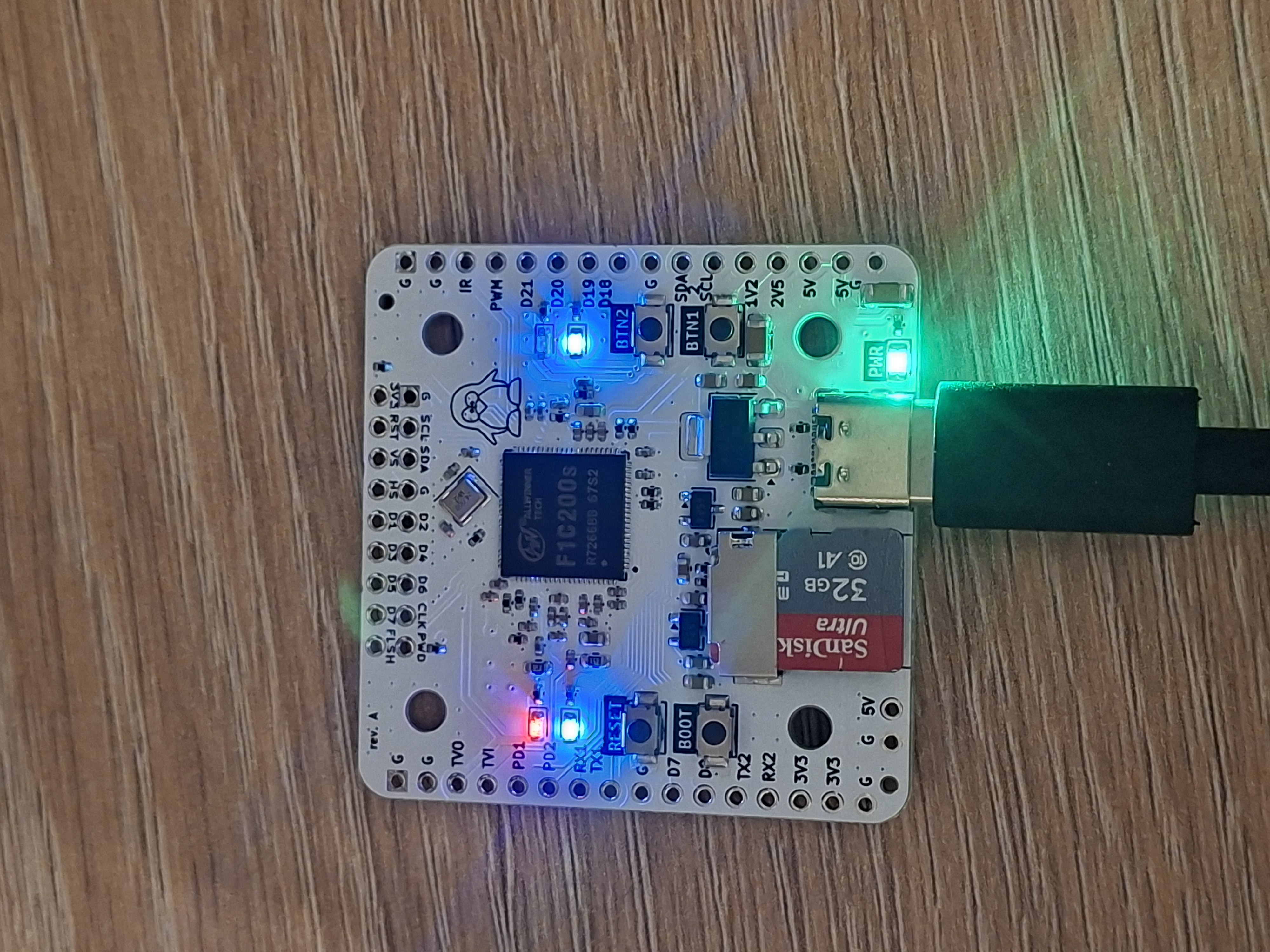
2026-04-20: First Linux boot! Rev A boards arrived and reached a busybox root shell
on UART0. The core path (USB-C power, DDR1, 24MHz PLL, MMC, pinctrl, UART, GPIO LEDs,
SPI) is all verified working under Linux 6.19.11. Later the same day, USB composite
gadget (CDC ECM ethernet + CDC ACM serial) came up — one USB-C cable now carries
power, a shell on /dev/ttyACM0, and a network link on usb0 (192.168.100.1).
Buttons work via the input subsystem (/dev/input/event0) after a kernel patch
that aligns suniv's pinctrl strict-mode behaviour with other sunxi SoCs.
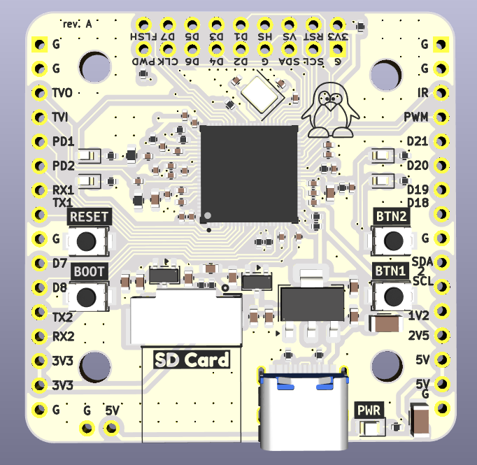
| Qty | Value | Footprint | References |
|---|---|---|---|
| 22 | 100nF | Capacitor_SMD:C_0402_1005Metric | C10, C11, C12, C13, C14, C15, C16, C17, C18, C20, C21, C32, C34, C36, C38, C39 +6 |
| 5 | 10k | Resistor_SMD:R_0402_1005Metric | R3, R9, R10, R18, R19 |
| 5 | 1k | Resistor_SMD:R_0402_1005Metric | R1, R2, R13, R14, R20 |
| 4 | 1uF | Capacitor_SMD:C_0603_1608Metric | C28, C29, C30, C31 |
| 4 | 22uF | Capacitor_SMD:C_0603_1608Metric | C22, C23, C26, C27 |
| 4 | 4.7k | Resistor_SMD:R_0402_1005Metric | R16, R17, R21, R22 |
| 4 | SW_SPST | easyeda2kicad:SW-SMD_L3.9-W3.0-P4.45 | SW1, SW2, SW3, SW4 |
| 3 | 10uF | Capacitor_SMD:C_0603_1608Metric | C1, C24, C25 |
| 2 | 100uF | Capacitor_SMD:C_1206_3216Metric | C33, C35 |
| 2 | 18pF | Capacitor_SMD:C_0402_1005Metric | C2, C3 |
| 2 | 1uF | Capacitor_SMD:C_0402_1005Metric | C19, C40 |
| 2 | 2.2k | Resistor_SMD:R_0402_1005Metric | R6, R8 |
| 2 | 22 | Resistor_SMD:R_0402_1005Metric | R4, R5 |
| 2 | 5.1k | Resistor_SMD:R_0402_1005Metric | R7, R11 |
| 2 | 75 | Resistor_SMD:R_0603_1608Metric | R15, R24 |
| 2 | RED | LED_SMD:LED_0603_1608Metric | D3, D4 |
| 2 | YELLOW | LED_SMD:LED_0603_1608Metric | D1, D2 |
| 1 | 10uF | Capacitor_SMD:C_0402_1005Metric | C37 |
| 1 | 24 MHz | Crystal:Crystal_SMD_3225-4Pin_3.2x2.5mm | Y1 |
| 1 | 33 | Resistor_SMD:R_0402_1005Metric | R12 |
| 1 | AMS1117-3.3 | Package_TO_SOT_SMD:SOT-223-3_TabPin2 | U3 |
| 1 | Camera | Connector_PinSocket_2.54mm:PinSocket_2x09_P2.54mm_Vertical | J4 |
| 1 | F1C200S | easyeda2kicad:QFN-88_L10.0-W10.0-P0.40-BL-EP6.75 | U1 |
| 1 | G*** | kibuzzard-69D20BF5 | kibuzzard-69D20BF5 |
| 1 | G*** | kibuzzard-69D21F31 | kibuzzard-69D21F31 |
| 1 | G*** | kibuzzard-69D21F51 | kibuzzard-69D21F51 |
| 1 | G*** | kibuzzard-69D21EBA | kibuzzard-69D21EBA |
| 1 | G*** | kibuzzard-67EE0EFE | kibuzzard-67EE0EFE |
| 1 | G*** | kibuzzard-69D21EC5 | kibuzzard-69D21EC5 |
| 1 | GREEN | LED_SMD:LED_0805_2012Metric | D5 |
| 1 | GT-USB-7010AN | SkyCircuitry_Lib:USB-SMD_GT-USB-7010AN | U9 |
| 1 | Left | Connector_PinSocket_2.54mm:PinSocket_1x16_P2.54mm_Vertical | J7 |
| 1 | Micro_SD_Card | easyeda2kicad:TF-SMD_TF-021B-H265 | J1 |
| 1 | Power | Connector_PinSocket_2.54mm:PinSocket_1x02_P2.54mm_Vertical | J2 |
| 1 | Right | Connector_PinSocket_2.54mm:PinSocket_1x16_P2.54mm_Vertical | J6 |
| 1 | XC6206P122MR | Package_TO_SOT_SMD:SOT-23-3 | U5 |
| 1 | XC6206P252MR | Package_TO_SOT_SMD:SOT-23-3 | U4 |
The 89 most common of 93 parts.


Alan-GIRAUDON/ESPCameleon
ESPCameleon is an ESP32 Camera PCB. It takes most of its design from the AI Thinker ESP32-Cam and adapt it to use the ESP32-S2-MINI-2-N4R2. This board allow video capture and streaming through WiFi or USB.

Alan-GIRAUDON/ESPCameleonV2
ESPCameleonV2 is an ESP32 Camera PCB. It resolve the biggest issues of its first version, ESP32Cameleon. This board allow video capture and streaming through WiFi or USB.

Nieko27/Frame-Workshop
A repo for all things steam frame hardware.

victorhook/f8-fc
f8 fc is a fully open source AIO flight controller with 8 motor drives

It measures 45 × 45 mm and has 2 copper layers, 1.6 mm thick.
93 parts, built around the F1C200S, AMS1117-3.3, GT-USB-7010AN and XC6206P122MR. The full list of its parts is on this page, with links to each part's symbol and footprint where PCBKit's library has them.
From the victorhook/F1C200S-Dev-board repository on GitHub, at the commit this page was made from: the board is F1C200S-Dev-board/F1C200S-Dev-board.kicad_pcb and its schematic F1C200S-Dev-board/F1C200S-Dev-board.kicad_sch. PCBKit opens the board in the browser, with nothing to install.
Its repository states no licence, so its author keeps all rights: ask victorhook before reusing the design.