
2 layers91 × 77 mm
Vga driverandaudioi2s driver
vatsgoyal27/pico_cyberdeck
attempting to buil a fucntioning cyberdeck with only rpi picos
41 parts1

 vatsgoyal27/pico_cyberdeck1
attempting to buil a fucntioning cyberdeck with only rpi picos
Custom split keyboard mouse is an open-source printed circuit board by vatsgoyal27, from the vatsgoyal27/pico_cyberdeck repository on GitHub. It is a 2-layer board of 344.4 × 104.3 mm with 104 parts on 93 nets, routed with 515 tracks and 59 vias.
It is built around the WS2812B. Its parts include 49 diodes, 44 switches, 3 connectors and 1 IC. It belongs with the keyboards and input boards and the RP2040 boards of this library.
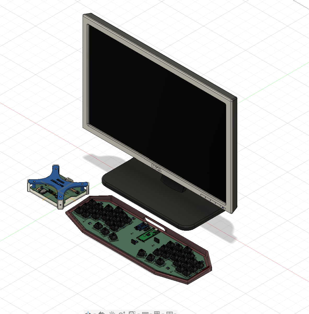 A custom cyberdeck built entirely around Raspberry Pi Pico 2 W boards instead of a traditional single-board computer (e.g. Raspberry Pi 4/5). Rather than one processor running the whole device, the deck is split into independent modules — each powered by its own Pico 2 W — handling a specific subsystem: display/audio, input (keyboard + joystick), Spotify display, UI, and network scanning.
Most cyberdecks are built around a full Linux-capable SBC (Raspberry Pi, Odroid, etc.) running a conventional OS with a desktop environment, shell, and multitasking kernel. This project takes a different approach:
This makes the build process, inter-module communication, and system architecture fundamentally different from a typical Pi-based cyberdeck, closer to a distributed embedded system than a general-purpose computer.
| Module | Role | Status |
|---|---|---|
| Display + Audio Driver | Drives VGA output and mono audio | ✅ Complete |
| Input Handler — Keyboard + Joystick | Custom mechanical keyboard with integrated analog joystick | ✅ Complete |
| Spotify Pico Display | LCD + TFT display module with joystick control | ✅ Complete |
| UI Controller | Renders menus/interface, coordinates modules | 🚧 In progress |
| Network Scanner | Wi-Fi/network scanning and analysis | 🚧 In progress |
Inter-module communication method (e.g. I2C/SPI/UART bus, or Wi-Fi between Pico 2 W boards) — TBD, document once finalized.
The first completed module. A Raspberry Pi Pico generates analog VGA video output and drives a mono audio amplifier.
| Component | Details |
|---|---|
| MCU | Raspberry Pi Pico (2 W) |
| Video Output | DE-15 (VGA) connector, resistor DAC for RGB |
| Audio | MAX98357A I2S mono Class D amplifier |
| Storage | MicroSD card slot |
| Mounting | 4x mounting holes |
Schematic and PCB design complete (KiCad, rev. 2026-06-01). Firmware for video timing generation and audio playback: document current state here.
A custom mechanical keyboard with an integrated analog joystick, serving as the cyberdeck's primary input module. Powered by its own Raspberry Pi Pico (RP2040).
This module is a fully custom keyboard PCB featuring an analog joystick for cursor/pointer control alongside the key matrix. It's built around a Raspberry Pi Pico, with onboard Li-Po battery charging for wireless/portable use.
| Component | Details |
|---|---|
| MCU | Raspberry Pi Pico |
| Switches | ~44x mechanical key switches (SW1–SW44) |
| Diodes | Per-key diodes (1N4148 or similar) for matrix scanning |
| Charging | TP4056 Micro-USB/USB-C Li-Po charger |
| Input | Analog joystick module |
| Connectors | 2x05 and 2x10 pin sockets (peripheral connections) |
| Battery | Li-Po (connector on board) |
Hardware and firmware complete.
A display module combining a character LCD and a TFT screen with joystick input, driven by a Raspberry Pi Pico 2 W. Displays Spotify playback info (album art, track data) on the cyberdeck.
MCU: Raspberry Pi Pico 2 W
LCD (LiquidCrystal — 4-bit mode)
| Function | GPIO |
|---|---|
| RS | 2 |
| EN | 3 |
| D4 | 4 |
| D5 | 5 |
| D6 | 6 |
| D7 | 7 |
Joystick (Analog)
| Function | GPIO | Notes |
|---|---|---|
| X | 26 | ADC0 |
| Y | 27 | ADC1 |
| SW | 22 | INPUT_PULLUP |
TFT Display (ST7735 — SPI)
| Function | GPIO |
|---|---|
| CS | 17 |
| DC | 20 |
| RST | 21 |
| SCK | 18 |
| MOSI | 19 |
| MISO | 16 |
The temporary GIF display is implemented using image_to_c.
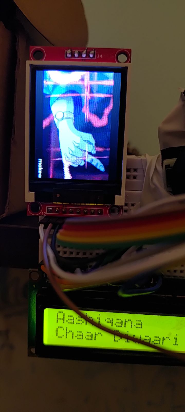
Hardware and firmware complete.
Each module runs independently on its own Pico / Pico 2 W. Firmware approach (MicroPython / CircuitPython / C SDK) — to be finalized per module.
🚧 Work in progress — Display + Audio, Input Handler, and Spotify Pico Display modules complete; UI and Network Scanner modules in development.
| Qty | Value | Footprint | References |
|---|---|---|---|
| 42 | D | Diode_THT:D_DO-35_SOD27_P7.62mm_Horizontal | D1, D2, D10, D11, D12, D13, D14, D15, D16, D17, D18, D19, D20, D21, D22, D23 +26 |
| 42 | SW_Push | custom_shit:SW_MX1A-11NN-keyboardmech | SW1, SW2, SW10, SW11, SW12, SW13, SW14, SW15, SW16, SW17, SW18, SW19, SW20, SW21, SW22, SW23 +26 |
| 7 | WS2812B | LED_SMD:LED_WS2812B_PLCC4_5.0x5.0mm_P3.2mm | D43, D44, D45, D46, D47, D48, D49 |
| 6 | MountingHole | MountingHole:MountingHole_3mm | H2, H3, H6, H8, H9, H12 |
| 2 | SW_Push | Button_Switch_THT:SW_PUSH_6mm | SW43, SW44 |
| 1 | Conn_01x02_Pin | Connector_PinHeader_2.54mm:PinHeader_1x02_P2.54mm_Vertical | J3 |
| 1 | Conn_01x04_Socket | Connector_PinSocket_2.54mm:PinSocket_1x04_P2.54mm_Vertical | J1 |
| 1 | Conn_01x05_Socket | Connector_PinSocket_2.54mm:PinSocket_1x05_P2.54mm_Vertical | J2 |
| 1 | RaspberryPi_Pico | Module:RaspberryPi_Pico_Common_Unspecified | A1 |
| 1 | TP4056_MICRO-USB_CHARGER_-_1A | custom_shit:MODULE_TP4056_MICRO-USB_CHARGER_-_1A | U1 |
vatsgoyal27/pico_cyberdeck
attempting to buil a fucntioning cyberdeck with only rpi picos

fossasia/pslab-hardware
PSLab Hardware Design and Schematics https://pslab.io

FrameworkComputer/ExpansionCards
Reference designs and documentation to create Expansion Cards for the Framework Laptop


PrintersForAnts/Micron
If you want to purchase full kits there are 3 available (Kits are slowly updating to R1 hardware just make sure to double check the included hardware in your kit and if you have any questions reach out in the discord)


It measures 344.4 × 104.3 mm and has 2 copper layers, 1.6 mm thick.
104 parts, built around the WS2812B. The full list of its parts is on this page, with links to each part's symbol and footprint where PCBKit's library has them.
From the vatsgoyal27/pico_cyberdeck repository on GitHub, at the commit this page was made from: the board is custom_split_keyboard_mouse/custom_split_keyboard_mouse.kicad_pcb and its schematic custom_split_keyboard_mouse/custom_split_keyboard_mouse.kicad_sch. PCBKit opens the board in the browser, with nothing to install.
Its repository states no licence, so its author keeps all rights: ask vatsgoyal27 before reusing the design.