

2 layers96.5 × 53.3 mm

 VasilKalchev/LEDDs2
PCB and enclosure design of a trailing edge light bulbs dimmer
LEDDs is an open-source printed circuit board by VasilKalchev, from the VasilKalchev/LEDDs repository on GitHub, published under the MIT licence. It is a 2-layer board of 95 × 46 mm with 91 parts on 59 nets, routed with 460 tracks and 92 vias.
It is built around the HLK-PM03, AP2112K-3.3 and ESP32-C3-12F, with the H11L1SR2M, 1N4148W and MMBT3904 among its other parts. Its parts include 31 resistors, 16 capacitors, 13 diodes, 6 transistors and 5 ICs. It belongs with the home automation and IoT boards and the ESP32 and RISC-V boards of this library.


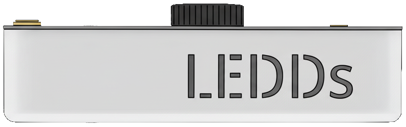
trailing-edge dimmer for LED bulbs


LEDDs is an open-source hardware, DIY, smart dimmer for 230 V LED bulbs. It is built around the ESP32-C3-12F and is designed to sit on a desk or table, replacing standard inline cord switches.
The project consists of a PCB, a 3D-printable chassis, and a top plate designed as a PCB. It runs ESPHome for integration with Home Assistant and features a rotary encoder so it can be controlled easily or used as a standalone device.

[!CAUTION] MAINS VOLTAGE: This device operates at 230 VAC. Touching live components can result in serious injury or death.
- Only build if you have relevant experience with high-voltage electronics.
- Always unplug before opening!
- While the design includes safety features (fuse, MOVs), it is not a certified design and should be treated with caution.
This project is suitable if you:
This project is NOT suitable if you:
Most dimmers use leading-edge (TRIAC) dimming (designed for incandescent bulbs). They modulate power to the load by cutting the beginning of the AC half cycle. This creates a voltage spike that can cause buzzing and reduced lifespan in the capacitive power supplies found in LED bulbs.
LEDDs uses trailing-edge dimming. By using MOSFETs to cut the waveform at the end of the AC cycle, there isn't a positive voltage spike. This results in:
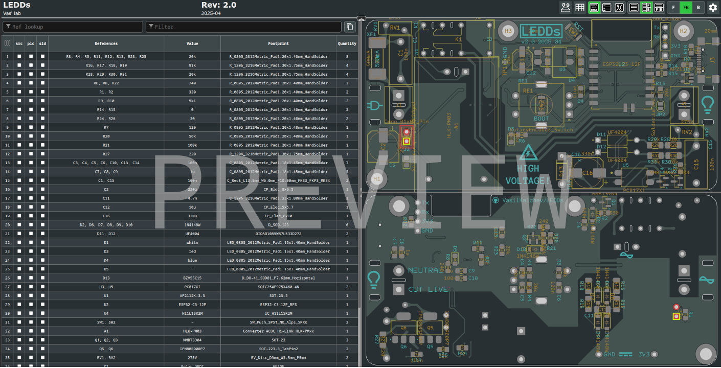
The schematic and PCB can be viewed in KiCanvas.
| Parameter | Value |
|---|---|
| Input voltage | 230 VAC |
| Maximum output power | 100 W |
| Idle power draw | ~0.3 W |
| Protections | fuse and MOVs |
| Microcontroller module | ESP32-C3-12F 1 |
| Dimensions | 100 × 51 × 25 mm (W × D × H) |
| Connectivity | Wi-Fi, USB-C (programming) |
[!IMPORTANT] Designed for 230 VAC at 50 Hz.
Usage with 120 VAC at 60 Hz will probably require adjusting the component values of the zero-cross and the voltage regulator circuits.
Status: Verified working. The fabricated board from this release is fully functional. Minor issues may exist but do not affect operation: /doc/releaselog.md v2.0.
:memo: Recommended for fabrication.


├── hw/                       # main PCB design (KiCad project)
│   ├── lib/                  # symbols and footprints
│   ├── assets/               # fonts and graphics
│   └── export/               # scripts for exporting gerbers, BOM and schematics/PCB PDFs
├── fw/                       # ESPHome YAML configurations and firmware binaries
├── doc/                      # additional documentation
│   ├── releaselog.md         # main PCB release log
│   ├── changelog.md          # main PCB change log
├── enclosure/
│   ├── chassis/              # 3D printable chassis
│   │   ├── releaselog.md     # chassis release log
│   │   ├── changelog.md      # chassis change log
│   │   ├── vX.Y-variant_a/
│   │   └── vX.Y-variant_b/
│   └── top_plate/            # top plate design (KiCad project)
│       ├── releaselog.md     # top plate release log
│       ├── changelog.md      # top plate change log
│       ├── vX.Y-variant_a/
│       └── vX.Y-variant_b/
└── img/ # photos and rendersCheck out the BOM provided in the release bundle for complete components list.
Building LEDDs consists of four main steps:
Download the release bundle.
[!TIP] Use the provided interactive BOM ("ibom.html") as a soldering guide.
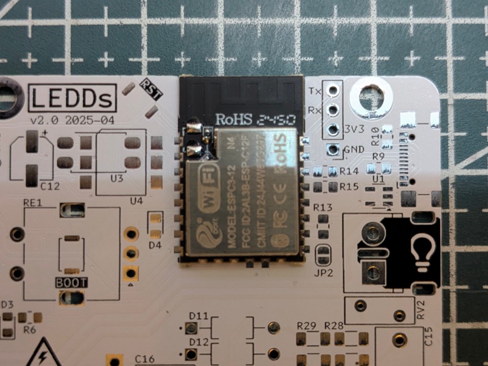
ESP32-C3-12F (recommended)
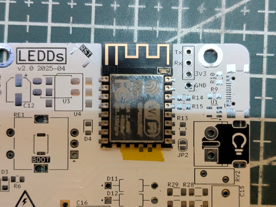
ESP8266 doesn't support native USB and requires an external USB to serial adapter for programming.
The PCB has footprints for a choice between 2 optoisolators that connect the zero-cross signal to the MCU.
H11L1SR2M
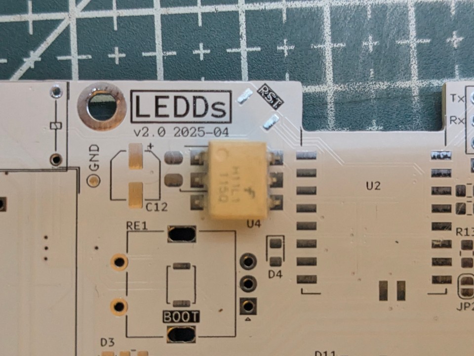
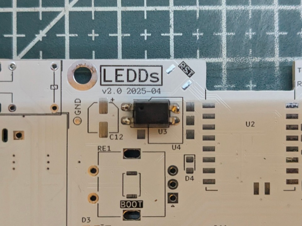
This optoisolator is the same as the one used for controlling the MOSFET's gate, but didn't work well for the zero-cross circuit.
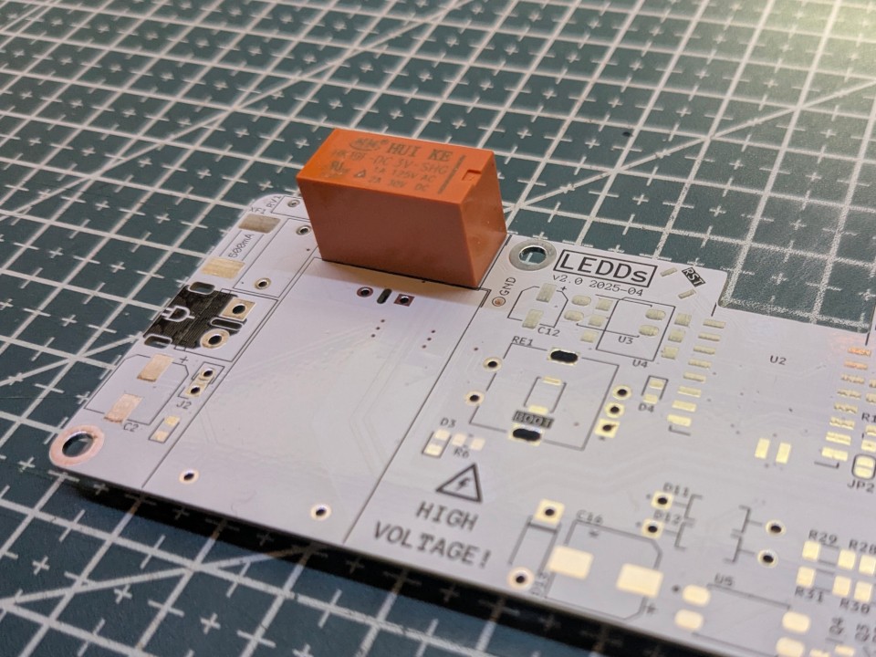
The relay is used to power off the mains part of the circuit when the load is turned off. This is intended as a peace of mind feature and can be omitted.
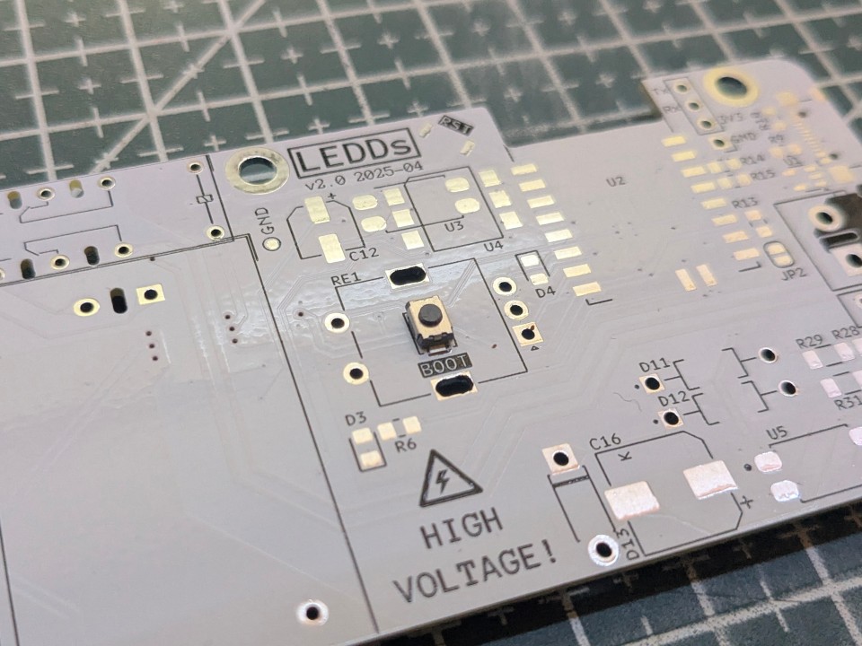
If the rotary encoder is not required - solder a push button (SW2) so boot mode can be entered manually.
A modified top plate (without a hole in the middle) is recommended for safety reasons (not currently available).
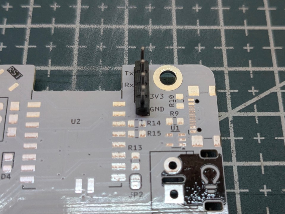
Use a USB to serial adapter.
[!TIP] The YAML configurations of the provided binaries are available under /fw/esphome/yaml/.
Directly (possible with all firmware variants):
Home Assistant (included in hass.bin):
Integrating the device in Home Assistant: https://esphome.io/guides/getting_started_hassio/#connecting-your-device-to-home-assistant.
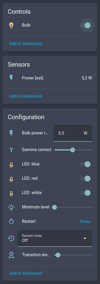
The "Configuration" section allows customization of the device:
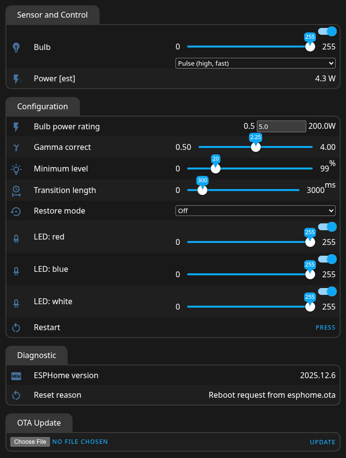
Web server (included in web_server.bin):
This is useful if you don't have Home Assistant, but want to control the device remotely.
There are three LEDs on the board:
Light effects can be cycled with the rotary encoder or chosen directly from a UI.
Each fabrication run results in a GitHub release.
Every type of contribution is welcome, like improvements or corrections to the:
Contributions can be made as improvements or as variants (e.g. different enclosure design, ESPHome configuration, etc.).
gitGraph
    commit tag: "v1.0"
    branch improve_x
    checkout improve_x
    commit id: "Improve x"
    commit id: "Re-generate exports"
    commit id: "Update board documentation"
    checkout main
    merge improve_x tag: "v1.1"
    branch replace_y
    checkout replace_y
    commit id: "Replace y"
    commit id: "Generate exports"
    commit id: "Compile binaries"
    commit id: "Update all documentation"
    checkout main
    merge replace_y tag: "v2.0"
You're welcome to post your builds in Discussions: Show and tell.
This project is licensed under the MIT License.
Disclaimer: This project involves mains voltage electricity. The author assumes no liability for injury, damage, or regulatory violations. Build and use at your own risk. Ensure compliance with local electrical codes and regulations.
| Qty | Value | Footprint | References |
|---|---|---|---|
| 8 | 20k | Resistor_SMD:R_0805_2012Metric_Pad1.20x1.40mm_HandSolder | R3, R4, R5, R11, R12, R13, R23, R25 |
| 7 | 100n | Capacitor_SMD:C_0805_2012Metric_Pad1.18x1.45mm_HandSolder | C3, C4, C5, C6, C10, C13, C14 |
| 6 | 1N4148W | Diode_SMD:D_SOD-123 | D2, D6, D7, D8, D9, D10 |
| 4 | 20k | Resistor_SMD:R_1206_3216Metric_Pad1.30x1.75mm_HandSolder | R28, R29, R30, R31 |
| 4 | 91k | Resistor_SMD:R_1206_3216Metric_Pad1.30x1.75mm_HandSolder | R16, R17, R18, R19 |
| 3 | 1u | Capacitor_SMD:C_0805_2012Metric_Pad1.18x1.45mm_HandSolder | C7, C8, C9 |
| 3 | 20mm | MountingHole:MountingHole_3.2mm_M3_DIN965_Pad_TopBottom | H1, H2, H3 |
| 3 | 240 | Resistor_SMD:R_0805_2012Metric_Pad1.20x1.40mm_HandSolder | R6, R8, R22 |
| 3 | MMBT3904 | Package_TO_SOT_SMD:SOT-23 | Q1, Q2, Q3 |
| 2 | 0 | Resistor_SMD:R_0805_2012Metric_Pad1.20x1.40mm_HandSolder | R14, R15 |
| 2 | 100n | Capacitor_THT:C_Rect_L13.0mm_W6.0mm_P10.00mm_FKS3_FKP3_MKS4 | C1, C15 |
| 2 | 275V | Varistor:RV_Disc_D9mm_W3.5mm_P5mm | RV1, RV2 |
| 2 | 30 | Resistor_SMD:R_0805_2012Metric_Pad1.20x1.40mm_HandSolder | R24, R26 |
| 2 | 330 | Resistor_SMD:R_0805_2012Metric_Pad1.20x1.40mm_HandSolder | R1, R2 |
| 2 | 5k1 | Resistor_SMD:R_0805_2012Metric_Pad1.20x1.40mm_HandSolder | R9, R10 |
| 2 | IPN80R900P7 | Package_TO_SOT_SMD:SOT-223-3_TabPin2 | Q5, Q6 |
| 2 | PC817XI | PC817XI:SOIC254P975X460-4N | U3, U5 |
| 2 | Screw_Terminal_01x02 | TerminalBlock:TerminalBlock_bornier-2_P5.08mm | J1, J5 |
| 2 | UF4004 | UF4004:DIOAD1055W87L533D272 | D11, D12 |
| 2 | ~ | Button_Switch_SMD:SW_Push_SPST_NO_Alps_SKRK | SW1, SW2 |
| 1 | 100k | Resistor_SMD:R_0805_2012Metric_Pad1.20x1.40mm_HandSolder | R21 |
| 1 | 10u | Capacitor_SMD:CP_Elec_5x5.7 | C12 |
| 1 | 120 | Resistor_SMD:R_0805_2012Metric_Pad1.20x1.40mm_HandSolder | R7 |
| 1 | 220 | Resistor_SMD:R_1206_3216Metric_Pad1.30x1.75mm_HandSolder | R27 |
| 1 | 220u | Capacitor_SMD:CP_Elec_8x6.5 | C2 |
| 1 | 330u | Capacitor_SMD:CP_Elec_8x10 | C16 |
| 1 | 4.7n | Capacitor_SMD:C_1206_3216Metric_Pad1.33x1.80mm_HandSolder | C11 |
| 1 | 500mA | Fuse:Fuse_Schurter_UMZ250 | XF1 |
| 1 | 56k | Resistor_SMD:R_0805_2012Metric_Pad1.20x1.40mm_HandSolder | R20 |
| 1 | AP2112K-3.3 | Package_TO_SOT_SMD:SOT-23-5 | U1 |
| 1 | BZV55C15 | Diode_THT:D_DO-41_SOD81_P7.62mm_Horizontal | D13 |
| 1 | Conn_01x02_Pin | Connector_PinSocket_2.54mm:PinSocket_1x02_P2.54mm_Vertical | J2 |
| 1 | Conn_01x06 | Connector_PinHeader_2.54mm:PinHeader_1x04_P2.54mm_Vertical | J4 |
| 1 | ESP32-C3-12F | ESP32-C3-12F:ESP32-C3-12F_RFS | U2 |
| 1 | GNDD | TestPoint:TestPoint_Pad_D1.0mm | TP1 |
| 1 | H11L1SR2M | H11L1SR2M:IC_H11L1SR2M | U4 |
| 1 | HLK-PM03 | Converter_ACDC:Converter_ACDC_Hi-Link_HLK-PMxx | A1 |
| 1 | MMBT3906 | Package_TO_SOT_SMD:SOT-23 | Q4 |
| 1 | Relay_DPDT | Relay:HK19F | K1 |
| 1 | RotaryEncoder_Switch | Rotary_Encoder:RotaryEncoder_Alps_EC11E-Switch_Vertical_H20mm | RE1 |
| 1 | SolderJumper_2_Bridged | Jumper:SolderJumper-2_P1.3mm_Bridged_RoundedPad1.0x1.5mm | JP1 |
| 1 | SolderJumper_2_Open | Jumper:SolderJumper-2_P1.3mm_Open_RoundedPad1.0x1.5mm | JP2 |
| 1 | USB_C_Receptacle_USB2.0_14P | Connector_USB:USB_C_Receptacle_GCT_USB4110 | J3 |
| 1 | blue | LED_SMD:LED_0805_2012Metric_Pad1.15x1.40mm_HandSolder | D4 |
| 1 | high voltage sign | LOGO | SS1 |
| 1 | red | LED_SMD:LED_0805_2012Metric_Pad1.15x1.40mm_HandSolder | D3 |
| 1 | white | LED_SMD:LED_0805_2012Metric_Pad1.15x1.40mm_HandSolder | D1 |
| 1 | ~ | LED_SMD:LED_0805_2012Metric_Pad1.15x1.40mm_HandSolder | D5 |
It measures 95 × 46 mm and has 2 copper layers, 1.1 mm thick.
91 parts, built around the HLK-PM03, AP2112K-3.3, ESP32-C3-12F and H11L1SR2M. The full list of its parts is on this page, with links to each part's symbol and footprint where PCBKit's library has them.
From the VasilKalchev/LEDDs repository on GitHub, at the commit this page was made from: the board is hw/LEDDs.kicad_pcb and its schematic enclosure/top_plate/v2.0-bicycle/hw/top_plate.kicad_sch. PCBKit opens the board in the browser, with nothing to install.
Its repository publishes it under the MIT licence: you may reuse it on that licence's terms (keep the author's notice, and for a copyleft licence share your changes alike).


sebasdv/pikocore_gamepad
Fork of pikocore ported to run on the Waveshare RP2350-PiZero + GamePi13 handheld — full-color LCD dashboard, 12-button menu, and save/load state on a lo-fi sampler that was originally knob-only.

almondsun/DynamicSystemsAndControl
Dynamic Systems and Control coursework: Buck converter modeling, reports, KiCad PCB and STM32 firmware

ondras12345/vetrnik
Electronics for heating water with power from a 2 kW wind turbine


JurCag/NB_IoT_app
Project utilizes NB-IoT technology to transmit sensory data to the cloud, while simultaneously enabling local communication through BLE mesh.

Mustafa614/Body-Control-Module-Mini
This Module are controlling wipers,baclights,door statues and comminicates with another ecu's via can bus