2 layers99 × 90 mm

 Valleeh/taptempo-box
Tap-tempo box: MIDI clock + switched tempo outputs, ATmega328P, perfboard and JLCPCB SMD versions, 3D-printed enclosure
Taptempo smd is an open-source printed circuit board by Valleeh, from the Valleeh/taptempo-box repository on GitHub, published under the MIT licence. It is a 2-layer board of 52 × 70 mm with 45 parts on 57 nets, routed with 399 tracks and 153 vias.
It is built around the ATMEGA328P-AU, CH340C and PC817C, with the AMS1117-5.0 and SS14 among its other parts. Its parts include 14 capacitors, 9 resistors, 8 connectors, 5 ICs and 4 diodes. It belongs with the lEDs and displays and audio and music boards and the AVR (ATmega, ATtiny) boards of this library.


A small foot/desk box that turns a tapped tempo into MIDI clock and two switched tempo outputs (3.5 mm TRS, opto-isolated), with an OLED display and a rotary encoder for fine adjustment. Built around an ATmega328P (Arduino Nano pinout).
| Folder | What it is | Status |
|---|---|---|
nano-perfboard/ | Arduino Nano + optocouplers on a 5 × 7 cm perfboard, hand-soldered. Beginner-friendly build guide. | Designed, layout checked |
smd-pcb/ | Custom 2-layer PCB (52 × 70 mm) assembled by JLCPCB: ATmega328P-AU, CH340C, USB-C, regulator on board. Same pin mapping, so the same firmware runs. | Designed, ERC/DRC clean, not built yet |
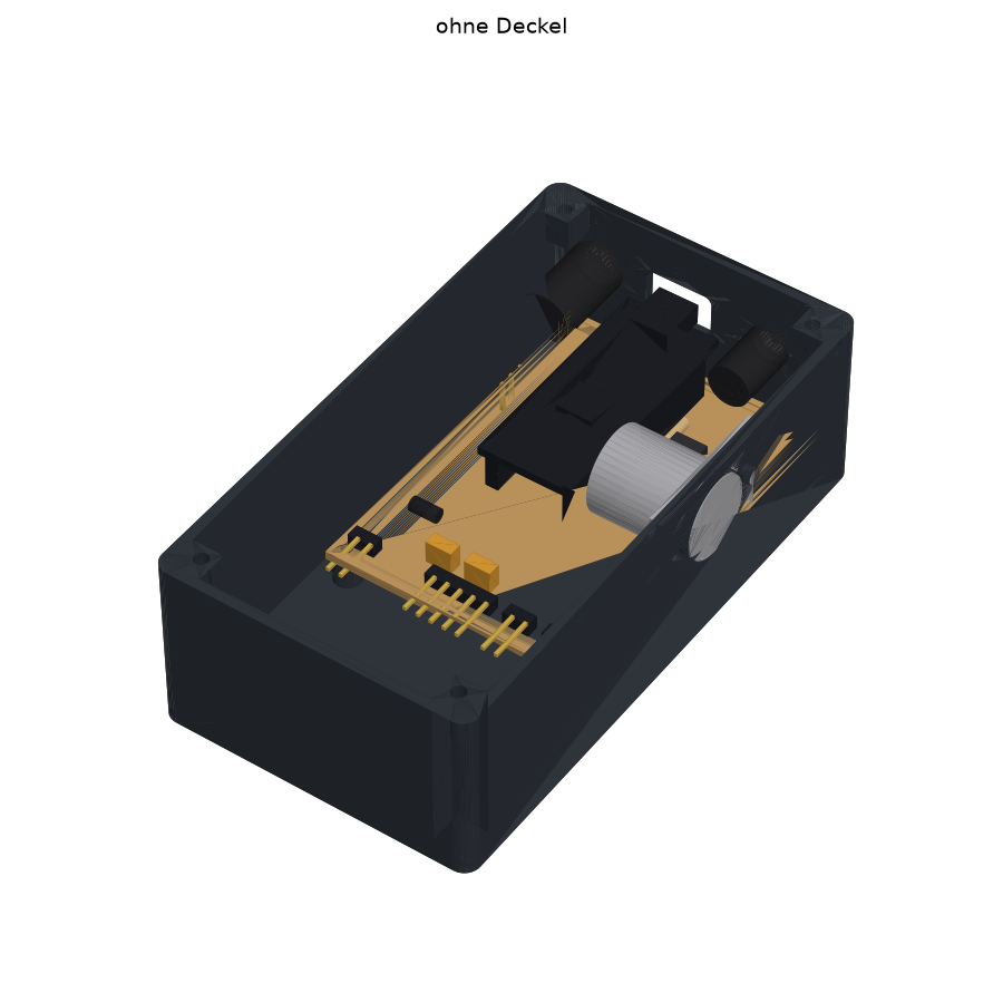
Both share the same 3D-printed enclosure (60 × 110 × 36 mm, CadQuery), adapted per version.
| Function | Arduino pin |
|---|---|
| TAP button (to GND, internal pull-up) | D5 |
| Start/Stop (encoder push button) | D4 |
| Encoder A / B | D3 / D2 |
| Switched output 1 → TRS tip (PC817, 220 Ω) | D10 |
| Switched output 2 → TRS ring (PC817, 220 Ω) | D9 |
| MIDI OUT (DIN pin 5 via 220 Ω) | D1 / TX |
| OLED SDA / SCL (SSD1306, I²C) | A4 / A5 |
| Power | 9 V barrel (center negative) → Schottky → VIN |
firmware/          Arduino sketches (currently a hardware test sketch, needs U8g2)
nano-perfboard/
  kicad/           KiCad 10 schematic + PDF
  perfboard/       perfboard layout as code (perfboard.py), drawings, build guide generator
  mech/            CadQuery enclosure, renders, collision check, STL/STEP output, 3D viewer
  share/           standalone offline HTML: build guide and 3D viewer
smd-pcb/
  kicad/           generated KiCad project (schematic, routed PCB, ERC/DRC reports)
  fab/             JLCPCB files: Gerber zip, BOM, CPL
  mech/            enclosure adapted to the SMD board
tools/ scripts that generate the whole KiCad project and fab filesnano-perfboard/mech/out/{tray,lid}.stl or smd-pcb/mech/out/{tray,lid}.stl (print the lid top side down)nano-perfboard/share/taptempo-bauanleitung.html in a browsernano-perfboard/share/taptempo-3d.htmlsmd-pcb/fab/ to JLCPCB, details in smd-pcb/README.mdEnclosure (needs CadQuery):
cd nano-perfboard/mech
python -m venv .venv && .venv/bin/pip install cadquery matplotlib
.venv/bin/python enclosure.py      # -> out/*.stl, *.step, *.glb
.venv/bin/python render.py         # -> out/view_*.png
Perfboard drawings and guide (plain Python 3):
cd nano-perfboard/perfboard
python3 drawings.py && python3 build_guide.py
cd ../share && python3 build_standalone.py
SMD board (needs KiCad 10 with its pcbnew Python module and kicad-cli):
smd-pcb/tools/build.shThe detailed build documentation is in German.
MIT, see LICENSE.
| Qty | Value | Footprint | References |
|---|---|---|---|
| 9 | 100nF | Capacitor_SMD:C_0603_1608Metric | C12, C13, C14, C15, C20, C21, C22, C30, C31 |
| 4 | 220 | Resistor_SMD:R_0603_1608Metric | R20, R21, R30, R31 |
| 4 | M3 | MountingHole:MountingHole_3.2mm_M3 | H1, H2, H3, H4 |
| 2 | 10uF | Capacitor_SMD:C_0805_2012Metric | C1, C16 |
| 2 | 12pF | Capacitor_SMD:C_0603_1608Metric | C10, C11 |
| 2 | 1k | Resistor_SMD:R_0603_1608Metric | R3, R11 |
| 2 | 5.1k | Resistor_SMD:R_0603_1608Metric | R1, R2 |
| 2 | PC817C | Package_DIP:SMDIP-4_W9.53mm | U4, U5 |
| 2 | SS14 | Diode_SMD:D_SMA | D1, D2 |
| 1 | 10k | Resistor_SMD:R_0603_1608Metric | R10 |
| 1 | 16MHz | Crystal:Crystal_SMD_3225-4Pin_3.2x2.5mm | Y1 |
| 1 | 22uF | Capacitor_SMD:C_0805_2012Metric | C2 |
| 1 | 3.5mm TRS (SJ1-3523N) | Connector_Audio:Jack_3.5mm_CUI_SJ1-3523N_Horizontal | J3 |
| 1 | 9V DC (PJ-102AH), Minus innen | Connector_BarrelJack:BarrelJack_CUI_PJ-102AH_Horizontal | J2 |
| 1 | AMS1117-5.0 | Package_TO_SOT_SMD:SOT-223-3_TabPin2 | U3 |
| 1 | ATmega328P-AU | Package_QFP:TQFP-32_7x7mm_P0.8mm | U1 |
| 1 | CH340C | Package_SO:SOIC-16_3.9x9.9mm_P1.27mm | U2 |
| 1 | Drehgeber (A GND B SW GND) | Connector_PinHeader_2.54mm:PinHeader_1x05_P2.54mm_Vertical | J5 |
| 1 | ISP (Bootloader) | Connector_PinHeader_2.54mm:PinHeader_2x03_P2.54mm_Vertical | J8 |
| 1 | LED_G (PWR) | LED_SMD:LED_0805_2012Metric | D3 |
| 1 | LED_R (L, D13) | LED_SMD:LED_0603_1608Metric | D10 |
| 1 | MIDI DIN (4, 2=GND, 5) | Connector_PinHeader_2.54mm:PinHeader_1x03_P2.54mm_Vertical | J7 |
| 1 | OLED (5V SDA SCL GND) | Connector_PinHeader_2.54mm:PinHeader_1x04_P2.54mm_Vertical | J4 |
| 1 | TAP (TAP GND) | Connector_PinHeader_2.54mm:PinHeader_1x02_P2.54mm_Vertical | J6 |
| 1 | USB-C (TYPE-C-31-M-12) | Connector_USB:USB_C_Receptacle_HRO_TYPE-C-31-M-12 | J1 |

CasuariusSYC/3-Phase-Electricity-Monitoring
This project is a module to monitor the status of a 3-phase electricity supply and record any power outages. The data can be accessed wirelessly. Currently, the features are limited to detecting the power state only.

wszeto9/2_679_PCB
PCB Project for 2.679 which is then used in my 2.007 Competition Robot

7bwiiza/Robot-creation
Uni project of a 3D model of a 5dof robot using Solidedge and motor control using KiCAD and MATLAB

jayanta525/dual-h-bridge
Dual H-Bridge Controller with IRF3205 and IR2104 MOSFET Driver, and with ATMega328P-AU PWM Controller

PaulBichl/vibepcb-smu
VibePCB example: 4-quadrant SMU (+-30 V / +-1 A, USB-C PD, Ethernet) designed with an LLM

Boardoza/Boardoza_PC817C_2CH_Isolated_Level_Shifter_Breakout_Board
Dual-channel optically isolated level shifter board using Sharp PC817C for safe voltage conversion between 3.3V–12V systems.

It measures 52 × 70 mm and has 2 copper layers, 1.6 mm thick.
45 parts, built around the ATMEGA328P-AU, CH340C, PC817C and AMS1117-5.0. The full list of its parts is on this page, with links to each part's symbol and footprint where PCBKit's library has them.
From the Valleeh/taptempo-box repository on GitHub, at the commit this page was made from: the board is smd-pcb/kicad/taptempo-smd.kicad_pcb and its schematic nano-perfboard/kicad/taptempo.kicad_sch. PCBKit opens the board in the browser, with nothing to install.
Its repository publishes it under the MIT licence: you may reuse it on that licence's terms (keep the author's notice, and for a copyleft licence share your changes alike).