2 layers32.9 × 24.2 mm

 uzzambutt/NorthernStudios-RX-Micro-ELRS-Receiver-2.4GHz1
Nano 2.4 GHz ExpressLRS Diversity PA/LNA Receiver
NS ELRS RX MICRO is an open-source printed circuit board by uzzambutt, from the uzzambutt/NorthernStudios-RX-Micro-ELRS-Receiver-2.4GHz repository on GitHub. It is a 4-layer board of 18.2 × 24.1 mm with 54 parts on 48 nets, routed with 432 tracks and 104 vias.
It is built around the ESP32-C3, SE2431L-R and SX1280IMLTRT, with the 2450FM07D0034 among its other parts. Its parts include 22 capacitors, 9 resistors, 5 connectors, 4 ICs and 3 inductors. It belongs with the ESP32 and RISC-V boards of this library.








An ultra-compact (18×24 mm), open-hardware 2.4 GHz ExpressLRS receiver featuring true antenna diversity, a high-power FEM (+20 dBm telemetry), integrated Wi-Fi ceramic antenna, and paneled breakaway rails for low-cost JLCPCB PCBA.
Key Specs • Visuals • Architecture • Pinout • PCB Stackup • Firmware Setup • BOM • License
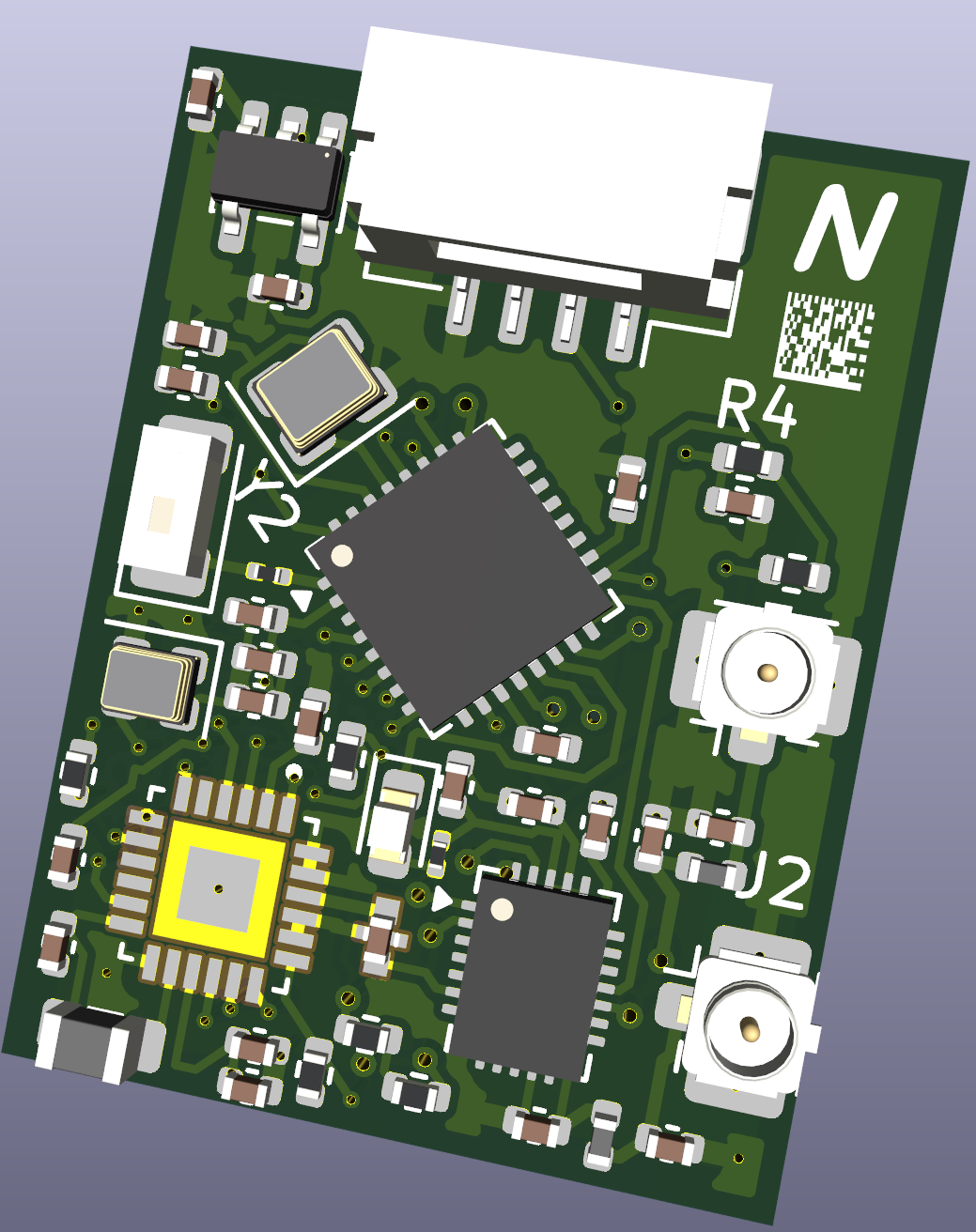
Figure 1: Production 3D Top Render of the Nano 2.4 GHz ExpressLRS Diversity PA/LNA Receiver
| Front Perspective (Core Silicon & RF Frontend) | Back Perspective (Passives, Testpads & Ground Plane) |
|---|---|
| 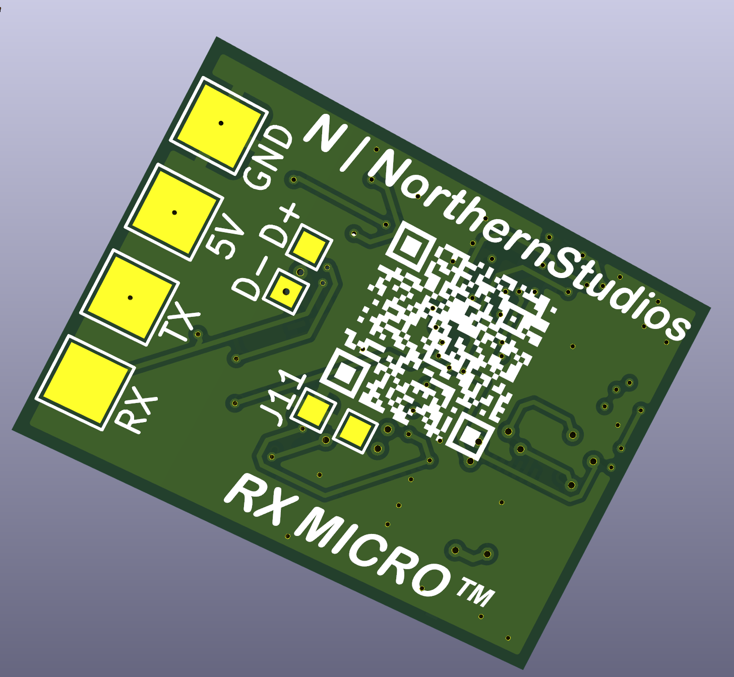 |
| Top Side (L1): ESP32-C3FH4, Semtech SX1280 Transceiver, Skyworks SE2431L PA/LNA FEM, 2450FM07D0034 Bandpass Filter, dual U.FL IPEX jacks, Johanson 2450AT ceramic chip antenna, status LED, crystals, and JST-GH connector. | Bottom Side (L4): Solid thermal relief stitching vias, dedicated USB test pads (USBD+/USBD-), BOOT strapping testpad, and low-impedance RF ground shield flood. |
The NorthernStudios Nano 2.4 GHz ExpressLRS Diversity Receiver is engineered for long-range, high-reliability UAV control links, telemetry backhaul, and high-interference drone racing / freestyle environments. Combining high-efficiency RISC-V computing with Semtech's SX1280 transceiver and Skyworks' SE2431L front-end module, it provides industrial-grade packet reception sensitivity, +20 dBm (100 mW) telemetry uplink, and seamless over-the-air firmware management.
| Category | Specification | Technical Implementation / Notes |
|---|---|---|
| Microcontroller (MCU) | ESP32-C3FH4 | 32-bit RISC-V single-core @ 160 MHz, 400 KB SRAM, 4 MB embedded SiP SPI flash |
| RF Transceiver | Semtech SX1280IMLTRT | 2.4 GHz LoRa, FLRC, and high-speed FSK modulation engine (-132 dBm sensitivity) |
| Front-End Module (FEM) | Skyworks SE2431L | Fully integrated RF front-end: +22 dB PA, +12.5 dB LNA (2.0 dB NF), SP3T RF switch |
| Telemetry Uplink Power | Up to 100 mW (+20 dBm) | Dynamic/fixed telemetry power configurable via ExpressLRS WebUI and Lua scripts |
| Primary Antenna Link | Dual U.FL / IPEX1 (ANT1 / ANT2) | True spatial and polarization diversity switched dynamically per-packet |
| Configuration Link | Johanson 2450AT18A100 | Dedicated onboard 2.45 GHz ceramic chip antenna for ESP32 Wi-Fi AP & WebUI |
| RF Filtering | Johanson 2450FM07D0034 | Matched high-rejection 2.4 GHz ceramic bandpass filter / balun |
| Active PCB Dimensions | 16.0 × 22.0 mm | Ultra-lightweight form factor suitable for sub-250g micros and long-range wings |
| Board Interface Pads | 2.54 mm Castellated Edges | 4-pin direct solder pads (5V, GND, TX, RX) + sub-miniature test points |
| Quick-Disconnect Plug | JST-GH 4-Pin Horizontal | Standard 1.25 mm pitch connector for direct drone flight controller wire harness |
| Panelized Manufacturing | 70.0 × 70.0 mm Breakaway | 0.6 mm perforated mouse-bite tabs, optical fiducials, and 3.2 mm tooling holes |
| Power Input Range | 4.5 V – 5.5 V DC | Onboard high-efficiency, low-noise TSOT-23-5 LDO producing clean 3.3 V @ 500 mA |
| Firmware Ecosystem | ExpressLRS v3.x / v4.x | Custom unified target definition via runtime hardware.json or config profiles |
The schematic is captured in KiCad 8/9 with complete hierarchical decoupling, controlled RF coplanar waveguides, and low-noise power distribution.
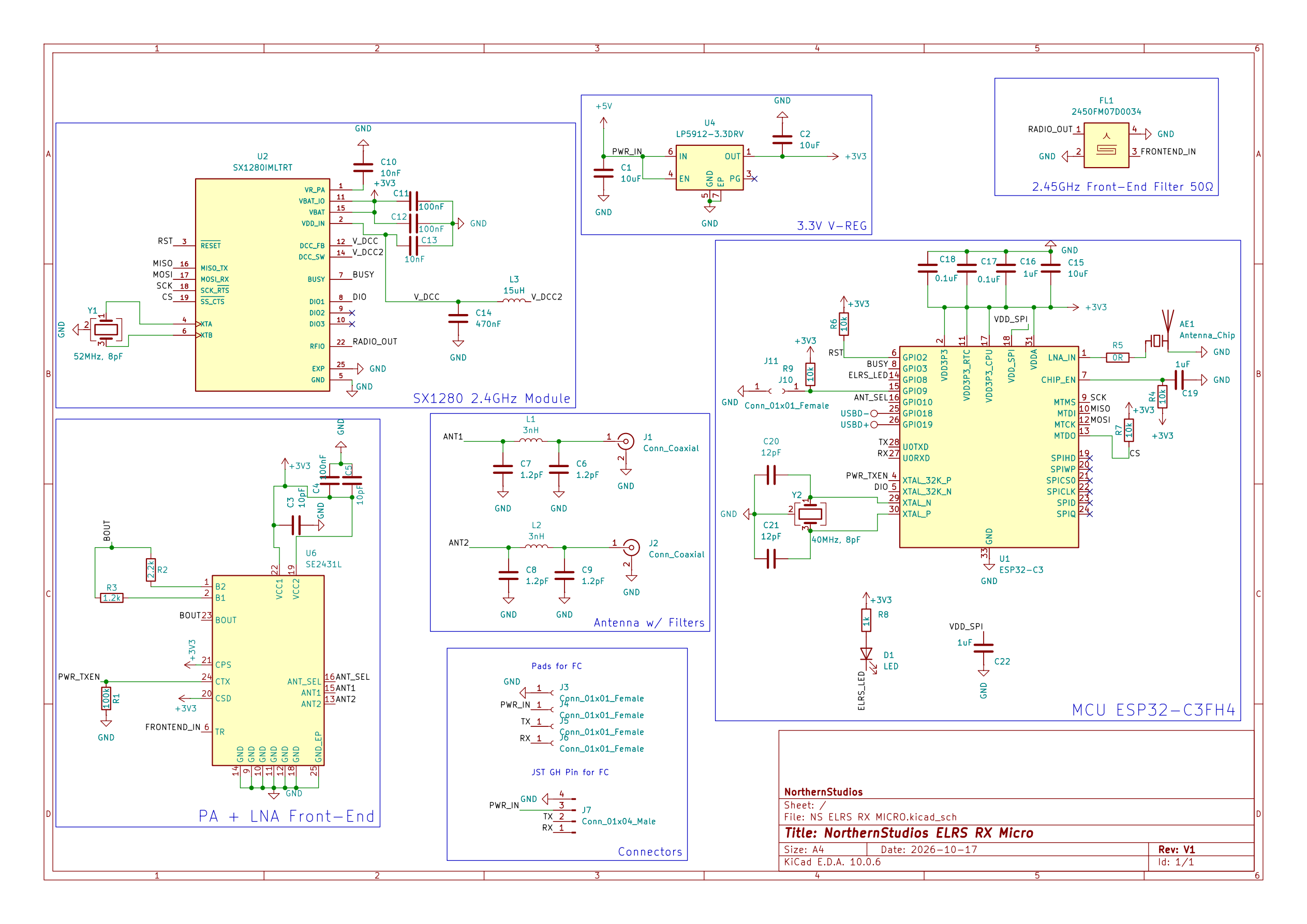
Figure 2: Complete Electrical Schematic — ESP32-C3FH4 Core, SX1280 2.4 GHz Transceiver, SE2431L Front-End Module, and Johanson RF Network
The receiver features two independent 2.4 GHz RF paths:
LNA_IN) directly to an onboard Johanson 2450AT ceramic chip antenna through a precision 50Ω Grounded Coplanar Waveguide (GCPW), isolating telemetry link tuning from configuration management.flowchart LR
subgraph Antennas ["Antenna System"]
A1["U.FL Antenna 1 (ANT1)"]
A2["U.FL Antenna 2 (ANT2)"]
AC["Johanson 2450AT Chip Antenna"]
end
subgraph FrontEnd ["RF Front-End (FEM)"]
SW{"SE2431L SP3T Switch"}
PA["Power Amp (+22 dB)"]
LNA["Low Noise Amp (+12.5 dB)"]
end
subgraph Filtering ["RF Conditioning"]
BPF["Johanson 2450FM07D0034 Filter"]
end
subgraph Silicon ["Core Transceiver & Processing"]
SX["Semtech SX1280 Transceiver"]
ESP["Espressif ESP32-C3FH4 (RISC-V)"]
end
subgraph Host ["Flight Controller Interface"]
FC["Flight Controller (CRSF UART)"]+---------------------------------------------------------------------------------------+
| ANTENNA SYSTEM |
| [U.FL Port 1] [U.FL Port 2] [Johanson 2450AT Chip] |
| | | | |
| +----------------+----------------+ | |
| | (50Ω GCPW) | (50Ω GCPW) |
| v | |
| +---------------------------------------+ | |
| | Skyworks SE2431L FEM | | |
| | [ANT Switch] <-> [PA / +22dB] | | |
| | <-> [LNA / +12.5dB] | | |
| +-------------------+-------------------+ | |
| ^ | |
| | (Tx / Rx Enable & Ant Sel) | |
| v | |
| +---------------------------------------+ | |
| | Johanson 2450FM07D0034 Filter | | |
| +-------------------+-------------------+ | |
| | (Matched Differential) | |
| v | |
| +---------------------------------------+ | |
| | Semtech SX1280 Transceiver | | |
| | 2.4 GHz LoRa / FLRC / FSK | | |
| +-------------------+-------------------+ | |The pin assignment is optimized for optimal trace routing on 4-layer PCBs, preserving signal integrity along high-speed SPI lines while isolating sensitive radio triggers from high-frequency clock harmonics.
| ESP32-C3 GPIO | Function / Net | ExpressLRS Definition | Description | Electrical Notes |
|---|---|---|---|---|
| GPIO02 | SX_RST | radio_rst | SX1280 Hardware Reset | Active Low; internal pull-up |
| GPIO03 | SX_BUSY | radio_busy | SX1280 Busy Status | Active High; polled before SPI transfers |
| GPIO04 | PWR_TXEN | power_txen | SE2431L Transmit Enable | High = PA Transmit Mode; Low = LNA Receive Mode |
| GPIO05 | SX_DIO1 | radio_dio1 | SX1280 Packet Interrupt | Active High; hardware interrupt for RX/TX events |
| GPIO06 | SCK | radio_sck | Hardware SPI Clock | Up to 18 MHz SPI master bus clock |
| GPIO07 | MISO | radio_miso | Hardware SPI Data In | Master-In Slave-Out from SX1280 |
| GPIO08 | ELRS_LED | led | Receiver Status LED | Active Low; tied to 3.3V via current-limit resistor |
| GPIO09 | BOOT | — | ESP32 Strapping / Boot | Pulled High internally; pull to GND for DFU UART flash |
| GPIO10 | ANT_SEL | ant_ctrl | SE2431L Antenna Switch | High = Antenna 2 (ANT2); Low = Antenna 1 (ANT1) |
| GPIO12 | MOSI | radio_mosi | Hardware SPI Data Out | Master-Out Slave-In to SX1280 |
| GPIO13 | SX_NSS | radio_nss | SX1280 Chip Select | Active Low SPI slave select |
| GPIO20 | U0RXD | serial_tx | ExpressLRS CRSF TX | Transmits CRSF packet frames to Flight Controller RX |
| GPIO21 | U0TXD | serial_rx | ExpressLRS CRSF RX | Receives serial channel/telemetry from Flight Controller TX |
       +---------------------------------------------+
       | [ANT1]                               [ANT2] |
       |                                             |
       |  (1) 5V   [ 4.5V - 5.5V DC Input ]          |
       |  (2) GND  [ Power & Signal Ground ]         |  Active PCB Area:
       |  (3) TX   [ CRSF Telemetry to FC RX ]       |  16.0 x 22.0 mm
       |  (4) RX   [ CRSF Control from FC TX ]       |
       |                                             |
       | [JST-GH] (1:GND, 2:5V, 3:TX, 4:RX)          |
       | [TP_BOOT] [TP_USBD-] [TP_USBD+]             |
+---------------------------------------------+BOOT (J10/J11), USBD- (TP1), and USBD+ (TP2) for debugging or manual recovery.The board utilizes a 4-layer controlled-impedance stackup specifically tailored for the JLCPCB JLC04161H-3313 or JLC04161H-7628 process.
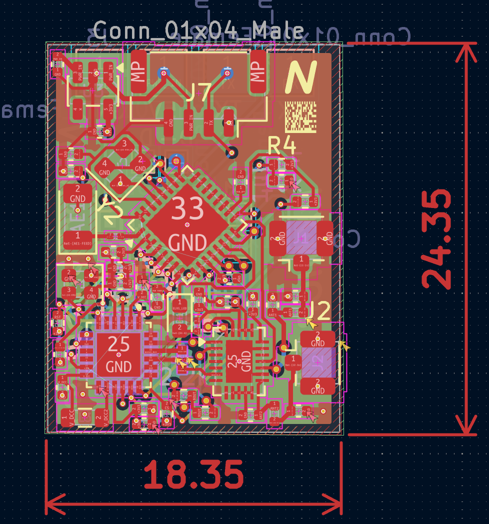
Figure 3: 4-Layer Controlled-Impedance Stackup (0.1 mm Prepreg / 1.6 mm Total Board Thickness)
| Layer | Type | Copper Thickness | Material | Description & RF Design Rules |
|---|---|---|---|---|
| L1 (Top) | Signal / RF | 1 oz (0.035 mm) | Copper | High-frequency 50Ω GCPW traces, critical components, antenna feed lines |
| Dielectric 1 | Core/Prepreg | 0.100 mm | FR4 (εr ≈ 4.5) | Prepreg layer providing tight capacitive coupling to Layer 2 GND |
| L2 (Inner 1) | Plane | 1 oz (0.035 mm) | Copper | Solid unbroken Ground reference plane. Zero cutouts under RF traces |
| Dielectric 2 | Core | 1.240 mm | FR4 (εr ≈ 4.5) | Rigid structural core isolating RF ground from digital power routing |
| L3 (Inner 2) | Power / Signal | 1 oz (0.035 mm) | Copper | Clean 3.3V power rails, LDO decoupling, non-critical control signals |
| Dielectric 3 | Core/Prepreg | 0.100 mm | FR4 (εr ≈ 4.5) | Dielectric insulation layer |
| L4 (Bottom) | Signal / Ground | 1 oz (0.035 mm) | Copper | Secondary ground flood, thermal vias, testpoints, and passive return paths |
0.18 mm (7.1 mil)0.15 mm (5.9 mil)0.10 mm (Prepreg to Layer 2 GND)The receiver is fabricated in a standardized 70 × 70 mm manufacturing panel frame containing:
[!TIP] Post-Reflow Breakaway Removal Instructions:
- Score the mouse bite tabs lightly using an engineer's carbide scribe or hobby hobby knife on both sides.
- Support the active receiver body flat against a bench surface and bend the outer rails downward with gentle, even pressure.
- Clip remaining nibs flush using precision flush cutters (e.g. Plato 170).
- Lightly dress the castellated edges with 400-grit abrasive paper to ensure no copper burrs short against the edge ground plane.
5V $\rightarrow$ 5V (or external clean 5V supply)GND $\rightarrow$ GNDTX $\rightarrow$ Adapter RXRX $\rightarrow$ Adapter TXBOOT test pad (GPIO09) to GND using tweezers or a jumper wire, then connect USB power to the adapter. Release the bridge after power is applied.Generic target using ESP32-C3 (or choose unified target)Generic ESP32-C3 2.4GHz RXUARTFCC / LBT), and Wi-Fi credentials.D1) will begin rapidly blinking (5 Hz).ExpressLRS RXexpresslrshttp://10.0.0.1 (or http://elrs_rx.local)..bin firmware file or modify runtime configuration values directly via the WebUI.hardware.json)To load the hardware pinout dynamically on unified ExpressLRS firmware builds, navigate to the Hardware tab in the WebUI and paste the following target definition:
{
  "target": "NS_ELRS_RX_MICRO_2400",
  "name": "NorthernStudios Nano 2.4GHz Diversity RX",
  "brand": "NorthernStudios",
  "radio": "sx1280",
  "mcu": "esp32c3",
  "serial_rx": 21,
  "serial_tx": 20,
  "radio_busy": 3,
  "radio_dio1": 5,
  "radio_miso": 7,
  "radio_mosi": 12,
  "radio_nss": 13,
  "radio_rst": 2,
  "radio_sck": 6,
  "power_txen": 4,
  "ant_ctrl": 10,
  "led": 8,
  "led_inverted": true,
  "power_min": 0,
  "power_high": 3,
  "power_max": 3,
  "power_default": 0,
  "power_control": 1,
  "power_values": [-18, -13, -9, -5, -2, 0, 3, 6, 10, 13]
}Every active IC, passive, and connector has been selected for high performance, standard commercial availability, and turnkey automated assembly via JLCPCB SMT / LCSC.
| Designator | Value / Part Number | Manufacturer | Description & Package | LCSC Part # | Sourcing Link |
|---|---|---|---|---|---|
| U1 | ESP32-C3FH4 | Espressif Systems | 32-bit RISC-V SoC, 4MB Flash, QFN-32 (5×5 mm) | Standard | Datasheet |
| U2 | SX1280IMLTRT | Semtech Corp. | 2.4 GHz LoRa/FLRC Transceiver, QFN-24 (4×4 mm) | Standard | Datasheet |
| U6 | SE2431L-R | Skyworks Solutions | High-Power FEM (PA + LNA + SP3T Switch), QFN-24 (3×4 mm) | C2649471 | Datasheet |
| U3 | SGM2036-3.3 / TSOT23 | SG Micro / Anyleaf | High PSRR, 500mA LDO Regulator, TSOT-23-5 | C587158 | LCSC |
| FL1 | 2450FM07D0034 | Johanson Technology | Matched 2.45 GHz Bandpass Filter/Balun, SMD-1109 | Standard | Johanson |
| AE1 | 2450AT18A100 | Johanson Technology | 2.45 GHz Ceramic Chip Antenna, SMD-3216 (1206) | Standard | Johanson |
| Designator | Quantity | Value / Specification | Footprint / Package | LCSC Part # | Notes |
|---|---|---|---|---|---|
| Y1 | 1 | 52 MHz, 8 pF, ±10 ppm | Crystal SMD 2016-4P (2.0×1.6 mm) | Standard | SX1280 Reference Clock |
| Y2 | 1 | 40 MHz, 8 pF, ±10 ppm | Crystal SMD 2520-4P (2.5×2.0 mm) | Standard | ESP32-C3 Reference Clock |
| J1, J2 | 2 | U.FL-R-SMT-1 (IPEX1) | Micro-Coaxial Surface Mount Jack | Standard | ANT1 / ANT2 RF Connectors |
| J7 | 1 | SM04B-GHS-TB (LF)(SN) | 4-Pin 1.25 mm Horizontal JST-GH | C189895 | Flight Controller Harness |
| D1 | 1 | LED Emerald Green / Blue | SMD 0603 (1608 Metric) | Standard | Status Indicator (Active Low) |
| L1, L2 | 2 | 3.0 nH High-Q Inductor | SMD 0402 (1005 Metric) | Standard | RF Matching Network |
| L3 | 1 | 15 µH Power Inductor | SMD 0805 (2012 Metric) | Standard | SX1280 DC-DC Buck Filter |
| C1 | 1 | 1 µF 10V X5R | SMD 0402 (1005 Metric) | C52923 | Decoupling |
| C2 | 1 | 2.2 µF 10V X5R | SMD 0402 (1005 Metric) | C12530 | LDO Output Bypass |
| C3, C5 | 2 | 10 pF 50V C0G/NP0 | SMD 0402 (1005 Metric) | Standard | RF Decoupling |
| C6, C7, C8, C9 | 4 | 1.2 pF 50V C0G/NP0 | SMD 0402 (1005 Metric) | Standard | RF Matching / Tuning |
| C4, C11, C12 | 3 | 100 nF 16V X7R | SMD 0402 (1005 Metric) | Standard | Digital Decoupling |
| C10, C13 | 2 | 10 nF 50V X7R | SMD 0402 (1005 Metric) | Standard | RF Power Rail Decoupling |
| C14 | 1 | 470 nF 10V X5R | SMD 0402 (1005 Metric) | Standard | Transceiver VDD |
| C15 | 1 | 10 µF 10V X5R | SMD 0402 (1005 Metric) | Standard | LDO Bulk Decoupling |
| C16, C19, C22 | 3 | 1 µF 10V X5R | SMD 0402 (1005 Metric) | Standard | Power Rail Smoothing |
| C17, C18 | 2 | 0.1 µF 16V X7R | SMD 0402 (1005 Metric) | Standard | Core Filtering |
| C20, C21 | 2 | 12 pF 50V C0G/NP0 | SMD 0402 (1005 Metric) | Standard | Crystal Load Capacitors |
| R1 | 1 | 100 kΩ 1% | SMD 0402 (1005 Metric) | Standard | Pull-down / Pull-up |
| R2 | 1 | 2.2 kΩ 1% | SMD 0402 (1005 Metric) | Standard | Pull-up |
| R3 | 1 | 1.2 kΩ 1% | SMD 0402 (1005 Metric) | Standard | LED Bias Limiter |
| R4, R6, R7, R9 | 4 | 10 kΩ 1% | SMD 0402 (1005 Metric) | C25744 | Reset & Mode Strapping |
| R5 | 1 | 0 Ω Jumper | SMD 0201 (0603 Metric) | Standard | RF Option Bridge |
| R8 | 1 | 1 kΩ 1% | SMD 0201 (0603 Metric) | Standard | Pull-up |
This project is licensed under the CERN Open Hardware Licence Version 2 – Strongly Reciprocal (CERN-OHL-S-v2).
[!WARNING] Radio Frequency Operating Compliance: This receiver is an open-source development device operating within the 2.400 GHz – 2.4835 GHz ISM band. Telemetry uplink operations can emit up to +20 dBm (100 mW) EIRP.
- Amateur Radio Licensing: Depending on your jurisdiction, transmitting at elevated telemetry power levels (+20 dBm) may require a valid Amateur Radio (Ham) license.
- European Union (CE / RED): Users operating within CE-compliant jurisdictions must configure ExpressLRS to use LBT (Listen-Before-Talk) mode with EIRP restricted to $\le 10\text{ dBm}$ (10 mW) or $\le 20\text{ dBm}$ with active LBT duty-cycling.
- United States (FCC Part 15 / Part 97): Operation must comply with FCC rules governing digital transmission systems within the 2.4 GHz band. The authors and contributors assume no liability for non-compliant RF transmission or unauthorized frequency usage.
Contributions, issue reports, and pull requests are welcomed!
| Qty | Value | Footprint | References |
|---|---|---|---|
| 4 | 1.2pF | Capacitor_SMD:C_0402_1005Metric | C6, C7, C8, C9 |
| 4 | 10k | Resistor_SMD:R_0402_1005Metric | R4, R6, R7, R9 |
| 4 | 1uF | Capacitor_SMD:C_0402_1005Metric | C1, C16, C19, C22 |
| 4 | Conn_01x01_Female | TestPoint:TestPoint_Pad_2.5x2.5mm | 5V, J3, RX, TX |
| 3 | 100nF | Capacitor_SMD:C_0402_1005Metric | C4, C11, C12 |
| 2 | 0.1uF | Capacitor_SMD:C_0402_1005Metric | C17, C18 |
| 2 | 10nF | Capacitor_SMD:C_0402_1005Metric | C10, C13 |
| 2 | 10pF | Capacitor_SMD:C_0402_1005Metric | C3, C5 |
| 2 | 12pF | Capacitor_SMD:C_0402_1005Metric | C20, C21 |
| 2 | 3nH | Inductor_SMD:L_0402_1005Metric | L1, L2 |
| 2 | Conn_01x01_Female | TestPoint:TestPoint_Pad_1.0x1.0mm | J10, J11 |
| 2 | Conn_Coaxial | Connector_Coaxial:U.FL_Hirose_U.FL-R-SMT-1_Vertical | J1, J2 |
| 1 | 0R | Resistor_SMD:R_0201_0603Metric | R5 |
| 1 | 1.2k | Resistor_SMD:R_0402_1005Metric | R3 |
| 1 | 100k | Resistor_SMD:R_0402_1005Metric | R1 |
| 1 | 10uF | Capacitor_SMD:C_0402_1005Metric | C15 |
| 1 | 15uH | Inductor_SMD:L_0805_2012Metric | L3 |
| 1 | 1k | Resistor_SMD:R_0201_0603Metric | R8 |
| 1 | 2.2k | Resistor_SMD:R_0402_1005Metric | R2 |
| 1 | 2.2uF | Capacitor_SMD:C_0402_1005Metric | C2 |
| 1 | 2450FM07D0034 | 2450FM07D0034:2450FM07D0034 | FL1 |
| 1 | 3.3V, 500mA | Package_TO_SOT_SMD:TSOT-23-5 | U3 |
| 1 | 40MHz, 8pF | Crystal:Crystal_SMD_2520-4Pin_2.5x2.0mm | Y2 |
| 1 | 470nF | Capacitor_SMD:C_0402_1005Metric | C14 |
| 1 | 52MHz, 8pF | Crystal:Crystal_SMD_2016-4Pin_2.0x1.6mm | Y1 |
| 1 | Antenna_Chip | RF_Antenna:Johanson_2450AT18x100 | AE1 |
| 1 | Conn_01x04_Male | Connector_JST:JST_GH_SM04B-GHS-TB_1x04-1MP_P1.25mm_Horizontal | J7 |
| 1 | ESP32-C3 | Package_DFN_QFN:QFN-32-1EP_5x5mm_P0.5mm_EP3.7x3.7mm | U1 |
| 1 | LED | LED_SMD:LED_0603_1608Metric | D1 |
| 1 | SE2431L | Package_DFN_QFN:QFN-24-1EP_3x4mm_P0.4mm_EP1.65x2.65mm | U6 |
| 1 | SX1280IMLTRT | SX1280IMLTRT:XCVR_SX1280IMLTRT | U2 |
| 1 | USBD+ | TestPoint:TestPoint_Pad_1.0x1.0mm | D+ |
| 1 | USBD- | TestPoint:TestPoint_Pad_1.0x1.0mm | D- |

LongDo1902/STM32_Drone
Developing quadcopter from scratch including stm32 programing and self-built flight controller PCB.

Paschalis/UAV-TelemetryLink
Receiver and transmitter solution for GCS using ELRS, mLRS, and MAVLink for reliable telemetry and control.

Paschalis/fc-plus-sensor-module
FC Plus is a modular add-on board for UAV flight controllers, providing advanced telemetry, GPS, object avoidance (ToF, Sonar, IR), and LED indicators for status feedback.


maholli/sx1280-breakout
breakout board for Semtech SX1280 LoRa radio compatible with RFM9x footprints

bastian2001/Kolibri-FC-Hardware
Hardware for the Kolibri Flight Controller. 30mm/20mm FC with RP2350 + ELRS onboard

It measures 18.2 × 24.1 mm and has 4 copper layers, 1.6 mm thick.
54 parts, built around the ESP32-C3, SE2431L-R, SX1280IMLTRT and 2450FM07D0034. The full list of its parts is on this page, with links to each part's symbol and footprint where PCBKit's library has them.
From the uzzambutt/NorthernStudios-RX-Micro-ELRS-Receiver-2.4GHz repository on GitHub, at the commit this page was made from: the board is NS ELRS RX MICRO.kicad_pcb and its schematic NS ELRS RX MICRO.kicad_sch. PCBKit opens the board in the browser, with nothing to install.
Its repository states no licence, so its author keeps all rights: ask uzzambutt before reusing the design.