
2 layers80 × 60 mm
EnvMonitor
kennySzhucheng/EnvMonitor
🌡️ 智能环境监测站 | STM32F103C8T6 + FreeRTOS + ESP8266 | 温湿度/光照/测距/OLED菜单/ThingSpeak上云 | 从裸机到RTOS到KiCad PCB全流程
27 parts10

 UtkuGokalp/stryx
A rolling robot I built to have a hardware platform on which to create embedded software projects.
Stryx is an open-source printed circuit board by UtkuGokalp, from the UtkuGokalp/stryx repository on GitHub, published under the MIT licence. It is a 2-layer board of 57 × 85 mm with 26 parts on 37 nets, routed with 225 tracks and 0 vias.
It is built around the HC-SR04. Its parts include 6 capacitors, 5 ICs, 4 resistors, 4 connectors and 3 diodes. It belongs with the robots and motor control boards of this library.
Stryx is a 3D printable wheeled robot designed as a platform for embedded software development. It has:
Below are the front, top and bottom views of Stryx.
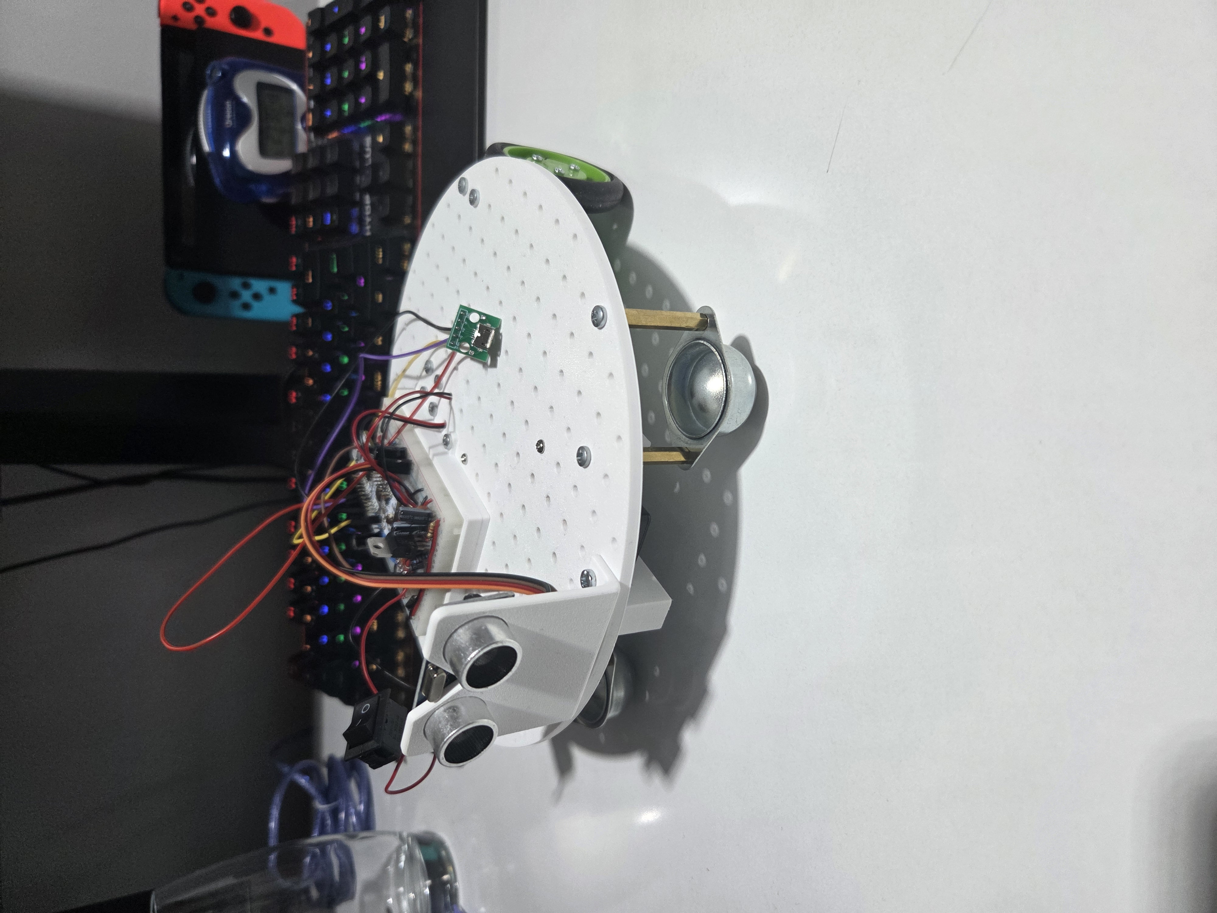
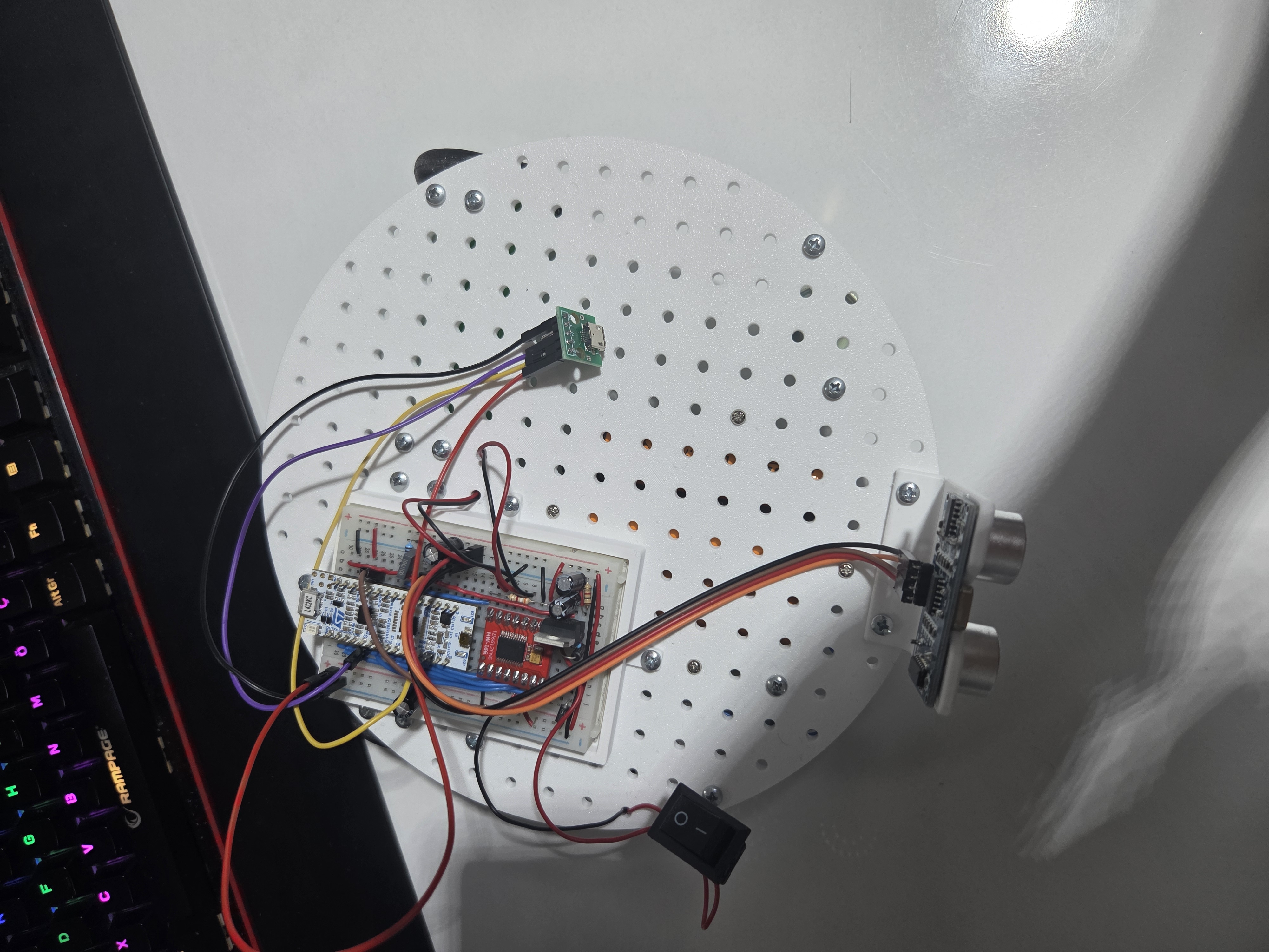
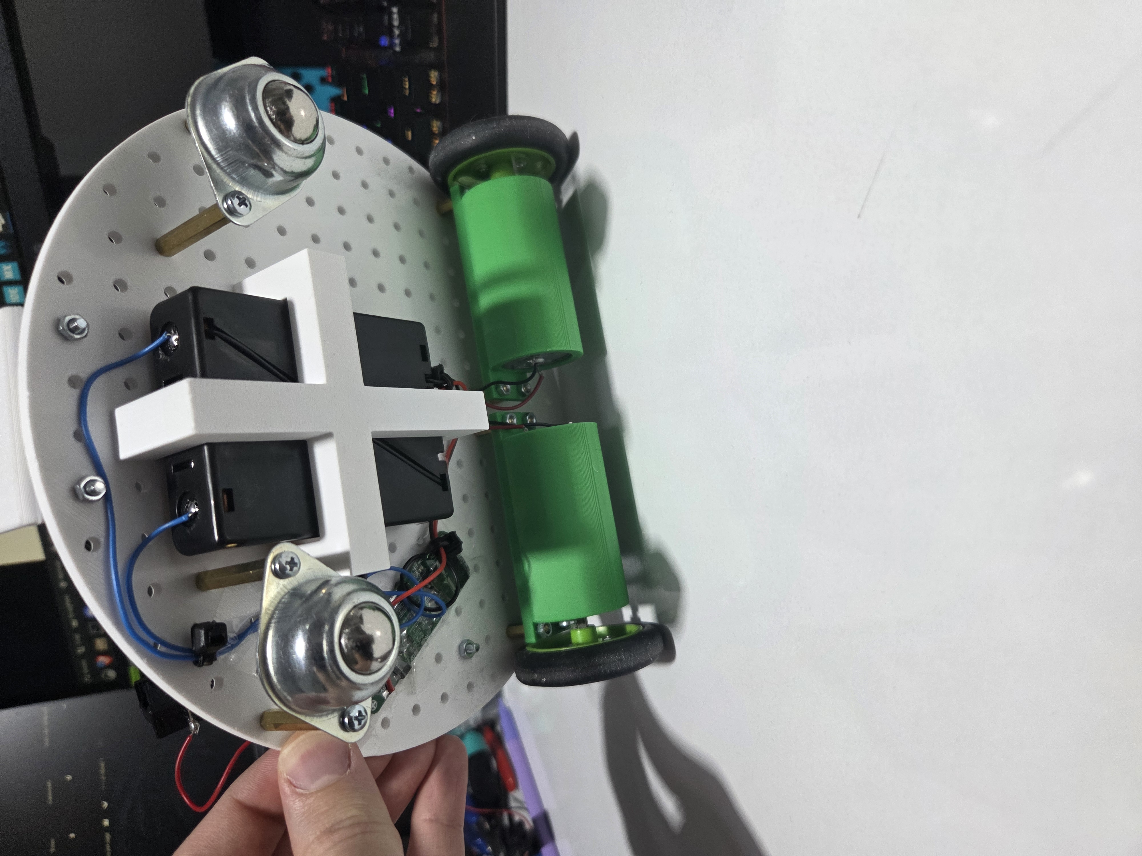
Current plans to improve this project are in the following order:
| Name | Amount |
|---|---|
| Mid-size breadboard | 1 |
| STM32 Nucleo L432KC Dev Board | 1 |
| USB Micro-B breakout board | 1 |
| TB6612FNG Module | 1 |
| 12V 250RPM DC Motors | 2 |
| Omnidirectional Wheels | 2 |
| LM317T Voltage regulator | 1 |
| 1N4001 | 3 |
| 1N5822 | 1 |
| 0.1uF ceramic capacitor | 2 |
| 1uF polarized capacitor | 1 |
| 10uF polarized capacitor | 1 |
| 470uF polarized capacitor | 2 |
| 240Ω resistor | 1 |
| 1kΩ resistor | 2 |
| 3.8kΩ resistor | 1 |
| Neopixel LED Module | 1 |
| HC-SR04 ultrasonic sensor | 1 |
| 3S 20A BMS | 1 |
| 3200mAh Li-ion batteries | 3 |
| 3S Li-ion battery holder | 1 |
| Switch (SPDT) | 1 |
| Screw Terminals | 3 |
| Rubber Wheels with D-Shaft connections | 2 |
| M3 screws, nuts, spacers and cables | various amounts |
Schematic is available in kicad_files/ folder along with a PDF for quick viewing of the schematic.
Note: PDF may be outdated. KiCad project is the most up to date schematic.
All 3D model files are in 3D_models/ folder along with printing instructions.
All parts are designed to align with the chassis mounting holes. Parts can be mounted wherever suitable, but keep in mind:
Components can be wired up according to the schematic in kicad_files/.
.ioc file.| Qty | Value | Footprint | References |
|---|---|---|---|
| 2 | 1N4001 | Diode_THT:D_DO-41_SOD81_P10.16mm_Horizontal | D2, D3 |
| 2 | 1k | Resistor_THT:R_Axial_DIN0207_L6.3mm_D2.5mm_P7.62mm_Horizontal | R1, R4 |
| 2 | 470uF 10V | Capacitor_THT:CP_Radial_D6.3mm_P2.50mm | C4, C5 |
| 1 | 0.1uF | Capacitor_THT:C_Rect_L7.0mm_W2.5mm_P5.00mm | C6 |
| 1 | 0.1uF | Capacitor_THT:C_Disc_D6.0mm_W2.5mm_P5.00mm | C1 |
| 1 | 10uF 50V | Capacitor_THT:CP_Radial_D5.0mm_P2.50mm | C2 |
| 1 | 1N5822 | Diode_THT:D_DO-201AD_P15.24mm_Horizontal | D1 |
| 1 | 1uF 50V | Capacitor_THT:CP_Radial_D5.0mm_P2.50mm | C3 |
| 1 | 240R | Resistor_THT:R_Axial_DIN0207_L6.3mm_D2.5mm_P7.62mm_Horizontal | R2 |
| 1 | 3.8k | Resistor_THT:R_Axial_DIN0207_L6.3mm_D2.5mm_P7.62mm_Horizontal | R3 |
| 1 | HC-SR04 | Connector_PinHeader_2.54mm:PinHeader_1x04_P2.54mm_Vertical | U3 |
| 1 | LM317_TO-220 | Package_TO_SOT_THT:TO-220-3_Vertical | U1 |
| 1 | NRF24L01_Breakout | RF_Module:nRF24L01_Breakout | U5 |
| 1 | NUCLEO-L432KC | footprints:MODULE_NUCLEO-L432KC | U2 |
| 1 | Screw_Terminal_M1 | TerminalBlock_MetzConnect:TerminalBlock_MetzConnect_Type171_RT13702HBWC_1x02_P7.50mm_Horizontal | J3 |
| 1 | Screw_Terminal_M2 | TerminalBlock_MetzConnect:TerminalBlock_MetzConnect_Type171_RT13702HBWC_1x02_P7.50mm_Horizontal | J2 |
| 1 | Screw_Terminal_Power | TerminalBlock_MetzConnect:TerminalBlock_MetzConnect_Type171_RT13702HBWC_1x02_P7.50mm_Horizontal | J1 |
| 1 | TB6612FNG-Module | footprints:MODULE_ROB-14450 | U4 |
| 1 | USB_B_Micro | Connector_PinHeader_2.54mm:PinHeader_1x05_P2.54mm_Vertical | J4 |
The 22 most common of 26 parts.
kennySzhucheng/EnvMonitor
🌡️ 智能环境监测站 | STM32F103C8T6 + FreeRTOS + ESP8266 | 温湿度/光照/测距/OLED菜单/ThingSpeak上云 | 从裸机到RTOS到KiCad PCB全流程


NikolaiRadke/Noko_2
The do-it-yourself Arduino-based Noko monster. Version 2 with PCB and 3D printed casing.

billtsol/Maze
This project demonstrates how to use an Arduino board, IR sensors, and a motor driver shield to create a maze-solving robot.

c-lydia/ESP-ROS2
A tiny robot with IMU (MPU5060) and an ultrasonic sensor (HC-SR04), running on micro-ROS, communicating over UDP.

dbrgn/crazyflie2-hcsr04
Ultrasonic sensor (HC-SR04) extension board for the Crazyflie 2.0

YousefAliAicha/aegis-embedded-system
Networked rotating ultrasonic radar system built on the Deneyap Kart 1A (ESP32-S3), with a real-time web dashboard served directly from the board.

YousefAliAicha/sentinel-arduino-firmware
Adaptive traffic-light FSM on the Arduino UNO R3 — pedestrian preemption, LDR-gated night mode with HC-SR04 vehicle detection, and a multiplexed 7-segment countdown. Fully non-blocking.
It measures 57 × 85 mm and has 2 copper layers, 1.6 mm thick.
26 parts, built around the HC-SR04. The full list of its parts is on this page, with links to each part's symbol and footprint where PCBKit's library has them.
From the UtkuGokalp/stryx repository on GitHub, at the commit this page was made from: the board is kicad_files/stryx.kicad_pcb and its schematic kicad_files/stryx.kicad_sch. PCBKit opens the board in the browser, with nothing to install.
Its repository publishes it under the MIT licence: you may reuse it on that licence's terms (keep the author's notice, and for a copyleft licence share your changes alike).