2 layers39 × 31 mm

 USI-27/microMouse
A fully autonomous micro mouse built from scratch
Mm3.0 is an open-source printed circuit board by USI-27, from the USI-27/microMouse repository on GitHub. It is a 2-layer board of 100 × 80 mm with 57 parts on 85 nets, routed with 429 tracks and 84 vias.
It is built around the AMS1117-5.0, MPU-6050 and TEFT4300, with the B6B-ZR and 1N4148WS among its other parts. Its parts include 18 capacitors, 13 resistors, 8 transistors, 6 diodes and 4 ICs. It belongs with the RP2040 boards of this library.


This project implements a micromouse robot using a Raspberry Pi Pico W microcontroller. The robot is designed to solve a maze using the flood fill algorithm, with advanced motion control, wall detection, and a custom-designed PCB.
MicroMouse/
├── MicroMouse Software/       # Firmware source code
│   ├── Headers/                # Header files (.h)
│   ├── images/                 # README images
│   ├── Cell.cpp
│   ├── IR_Sensors.cpp
│   ├── Int_Vector.cpp
│   ├── Maze_Algorithm.cpp
│   ├── Motion_Planner.cpp
│   ├── Profile.cpp
│   ├── Queue.cpp
│   └── Simple_Run_Micromouse_V1.ino
└── MicroMouse Design Files/   # Hardware design files
    ├── mm3.0/                  # KiCad project (schematic + PCB)
    ├── manufacturing/          # Gerbers, drill files, BOM, pick-and-place
    ├── images/                 # PCB and assembly renders
    ├── schematic.pdf
    └── HARDWARE.md             # Detailed hardware documentation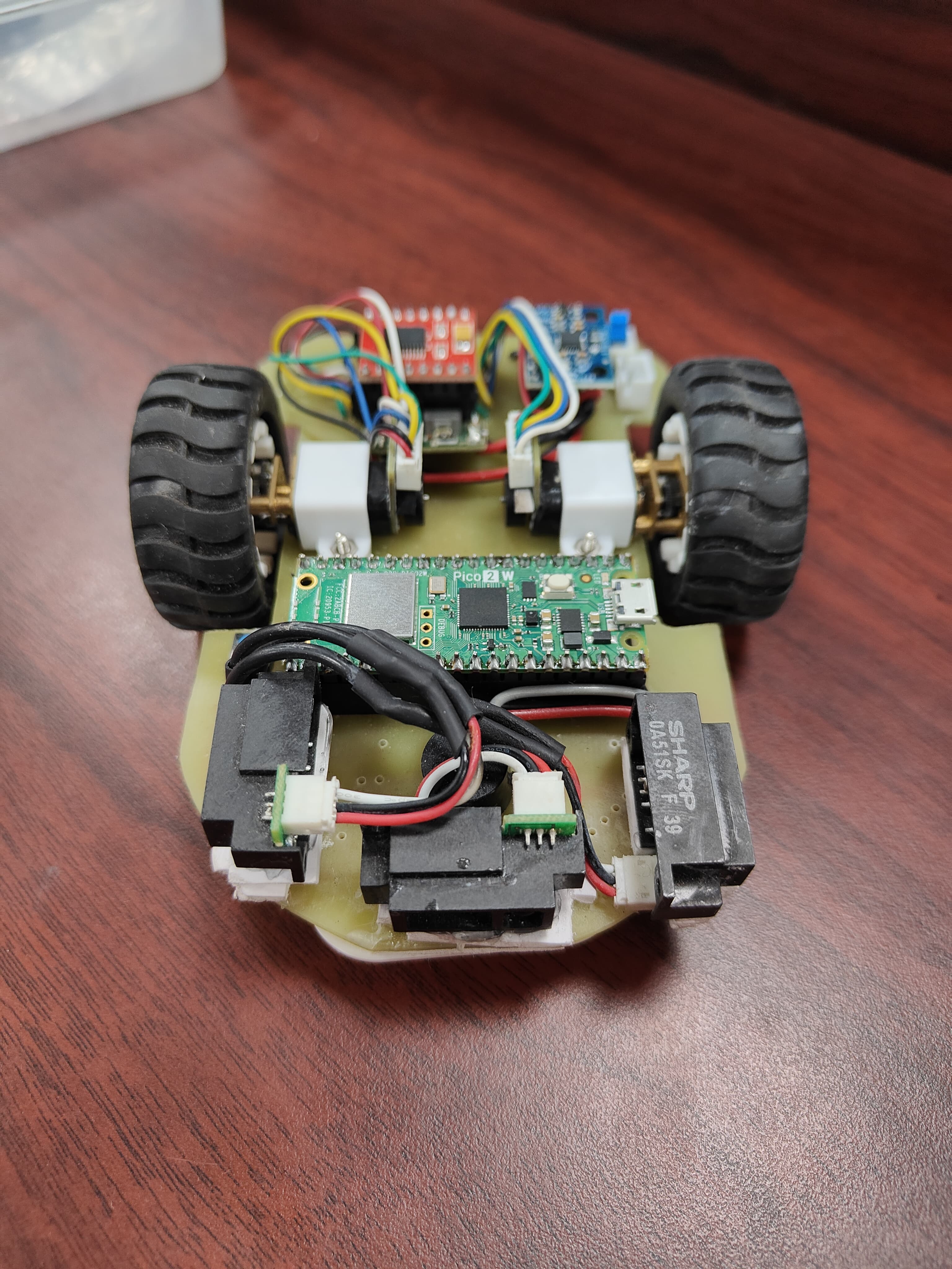
The image above shows the actual hardware implementation of the micromouse robot, featuring:
Full PCB schematics, KiCad source files, manufacturing (Gerber/BOM) files, and design writeups are available in MicroMouse Design Files/ — see HARDWARE.md for a detailed breakdown of the sensor placement and board layout.
Check out the micromouse robot in action: Watch on YouTube
The firmware is organized into several key components:
setup())The robot explores the maze in multiple rounds:
for (int round = 1; round <= Exploration_Rounds; round++) {
    searchMode = FIND_CENTRE;  // First find the center
    findGoal();
    searchMode = FIND_START;   // Then return to start
    findGoal();
}The flood fill algorithm works as follows:
The robot uses several movement functions:
moveForward(): Move one cell forwardturnLeft(): Turn 90 degrees leftturnRight(): Turn 90 degrees rightWall Update:
updateWalls(); // Detect and update wall informationPath Planning:
floodOpenNeighbours();     // Update cell costs
getMinDistanceDirection();  // Choose best direction
Movement:
moveInDirection(); // Execute movementAdaptive Movement:
Intelligent Maze Solving:
Robust Sensor Integration:
Key parameters can be adjusted in Profile.h:
MAZE_SIZE: Size of the maze (default: 8x8)Exploration_Rounds: Number of exploration roundsSimple_Run_Micromouse_V1.ino) to the Raspberry Pi Pico WBuilt by USI-27 and paramveer5404 .
| Qty | Value | Footprint | References |
|---|---|---|---|
| 5 | 100nF | Capacitor_SMD:C_0402_1005Metric_Pad0.74x0.62mm_HandSolder | C2, C4, C10, C12, C14 |
| 4 | 2K | Resistor_SMD:R_1206_3216Metric_Pad1.30x1.75mm_HandSolder | R2, R3, R4, R5 |
| 4 | 51k | Resistor_SMD:R_2010_5025Metric_Pad1.40x2.65mm_HandSolder | R7, R8, R9, R13 |
| 4 | 5MM Emitter | LED_THT:LED_D5.0mm_IRBlack | D2, D3, D4, D5 |
| 4 | DMN1019USN-7 | SPX3819M5-L-5-0:SOT95P285X140-3N | Q2, Q4, Q5, Q8 |
| 4 | TEFT4300 | LED_THT:LED_D3.0mm_Clear | Q1, Q3, Q6, Q7 |
| 3 | 4u7 | Capacitor_SMD:C_0805_2012Metric_Pad1.18x1.45mm_HandSolder | C9, C11, C13 |
| 2 | 10 ohm | Resistor_SMD:R_0805_2012Metric_Pad1.20x1.40mm_HandSolder | R6, R12 |
| 2 | 100nF | Capacitor_SMD:C_0805_2012Metric_Pad1.18x1.45mm_HandSolder | C6, C7 |
| 2 | 10uF | Capacitor_Tantalum_SMD:CP_EIA-3216-10_Kemet-I_Pad1.58x1.35mm_HandSolder | C1, C3 |
| 2 | 10uF | Capacitor_SMD:C_0805_2012Metric_Pad1.18x1.45mm_HandSolder | C5, C8 |
| 2 | 5.6ohm | Resistor_SMD:R_0402_1005Metric_Pad0.72x0.64mm_HandSolder | R10, R11 |
| 2 | B6B-ZR | B6B-ZR:B6B-ZR | X1, X2 |
| 2 | N20 | myTools:N20MotorWithMount | N20, N20 |
| 1 | 100n | Capacitor_SMD:C_0402_1005Metric_Pad0.74x0.62mm_HandSolder | C15 |
| 1 | 100n | Capacitor_SMD:C_0805_2012Metric_Pad1.18x1.45mm_HandSolder | C16 |
| 1 | 10n | Capacitor_SMD:C_0805_2012Metric_Pad1.18x1.45mm_HandSolder | C17 |
| 1 | 1K | Resistor_SMD:R_0402_1005Metric_Pad0.72x0.64mm_HandSolder | R1 |
| 1 | 1N4148WS | Diode_SMD:D_SOD-323_HandSoldering | D1 |
| 1 | 2n2 | Capacitor_SMD:C_0805_2012Metric_Pad1.18x1.45mm_HandSolder | C18 |
| 1 | AMS1117-5.0 | Package_TO_SOT_SMD:SOT-223-3_TabPin2 | U4 |
| 1 | B2B | Connector_JST:JST_XH_B2B-XH-AM_1x02_P2.50mm_Vertical | J1 |
| 1 | Buzzer | Buzzer_Beeper:Buzzer_12x9.5RM7.6 | BZ1 |
| 1 | LED_GREEN | LED_SMD:LED_0805_2012Metric_Pad1.15x1.40mm_HandSolder | D6 |
| 1 | LOGO | LOGO | logo |
| 1 | MPU-6050 | Sensor_Motion:InvenSense_QFN-24_4x4mm_P0.5mm | U3 |
| 1 | Pico | MCU_RaspberryPi_and_Boards:RPi_Pico_SMD_TH | U1 |
| 1 | TB6612FNG | Package_SO:SSOP-24_5.3x8.2mm_P0.65mm | U2 |
| 1 | ~ | TL2230EEF140:SW_TL2230EEF140 | S1 |
It measures 100 × 80 mm and has 2 copper layers, 1.6 mm thick.
57 parts, built around the AMS1117-5.0, MPU-6050, TEFT4300 and B6B-ZR. The full list of its parts is on this page, with links to each part's symbol and footprint where PCBKit's library has them.
From the USI-27/microMouse repository on GitHub, at the commit this page was made from: the board is MicroMouse Design Files/mm3.0/mm3.0.kicad_pcb and its schematic MicroMouse Design Files/mm3.0/mm3.0.kicad_sch. PCBKit opens the board in the browser, with nothing to install.
Its repository states no licence, so its author keeps all rights: ask USI-27 before reusing the design.


UBIEEE/FrankenMouse
FrankenMouse is a MicroMouse robot that was designed, built, and programmed from scratch by members of the University at Buffalo's IEEE Student Branch.


vorlaxen-labs/AratMicro
High-performance, open-source micromouse robot platform built for Robosam and MEB Robot (Ministry of National Education Robotics Competition, Turkey).

ChristopherAwomolo/Nova-Micromouse
Newer version based off the Futura Micromouse