4 layers70 × 99.9 mm
Micromouse
UBIEEE/FrankenMouse
FrankenMouse is a MicroMouse robot that was designed, built, and programmed from scratch by members of the University at Buffalo's IEEE Student Branch.
100 parts6MIT

 ChristopherAwomolo/Nova-Micromouse
Newer version based off the Futura Micromouse
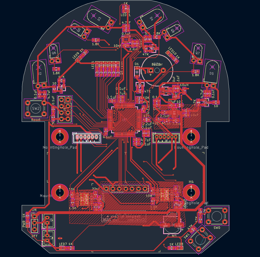
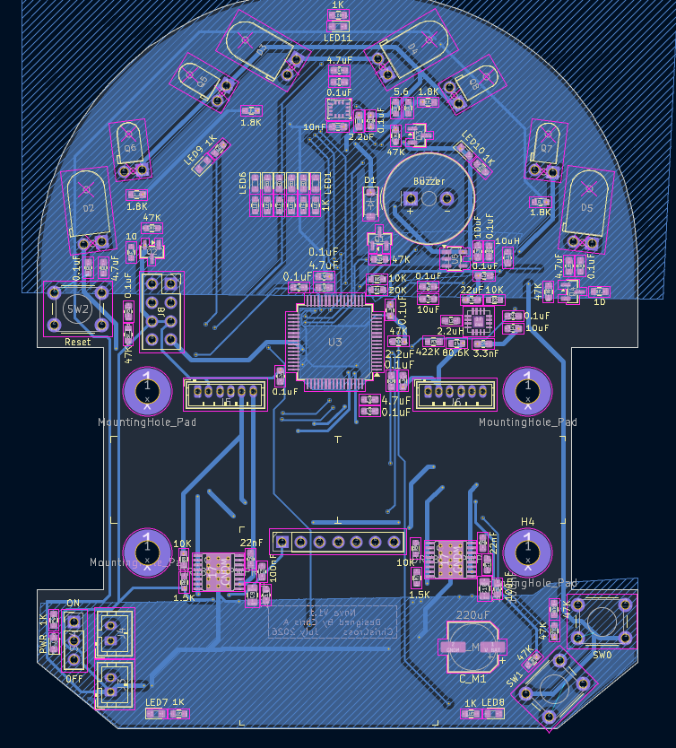
PCB Kicad is an open-source printed circuit board by ChristopherAwomolo, from the ChristopherAwomolo/Nova-Micromouse repository on GitHub, published under the MIT licence. It is a 4-layer board of 82 × 100 mm with 121 parts on 120 nets, routed with 1,081 tracks and 99 vias.
It is built around the TLV62130RGTR, ICM-42688-P and DMN3150L, with the SFH 4545, TEFT4300 and 1N4148W among its other parts. Its parts include 17 diodes, 9 capacitors, 9 resistors, 8 transistors and 6 ICs. It belongs with the STM32 boards of this library.


The next generation of the Futura Micromouse.
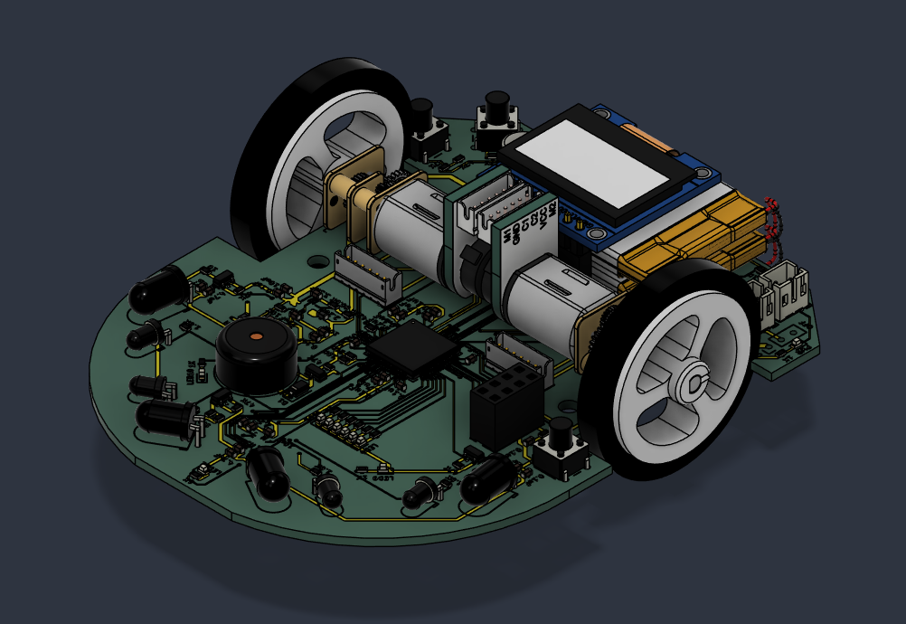


Nova is a maze-solving micromouse robot, built as a redesign and successor to an earlier build, the Futura Micromouse. The goal of the project is to design, fabricate, and program a small autonomous robot that can explore an unknown maze, build a map of it, and then run the shortest path from start to goal as fast as possible.
This repository currently hosts the electronics side of the project: a custom KiCad PCB that integrates the microcontroller, motor drivers, IR wall-detection sensors, IMU, power regulation, and status/UI hardware onto a single board designed to mount directly onto the mouse's chassis. Mechanical (CAD) design and firmware are in progress and will be added in due time.
A micromouse is a small autonomous robot that is able to find the center and "solve" a maze of an unknown layout. Competitors are scored on the time of their fastest successful run, which makes micromouse as much an exercise in embedded systems, control theory, and PCB/mechanical design as it is in pathfinding algorithms. For more info, I would highly recommend this video: (Click the image to open in a new tab)

Nova-Micromouse/
├── PCB_Kicad/                     # KiCad 10.0 project: schematics, PCB layout, libraries
│   ├── untitled.kicad_pro         # Project file
│   ├── untitled.kicad_sch         # Top-level schematic (hierarchical sheet)
│   ├── untitled.kicad_pcb         # PCB layout
│   ├── Micro_Controller.kicad_sch # STM32G4 MCU + programming header
│   ├── Power_System.kicad_sch     # Battery input, buck converter, LDO
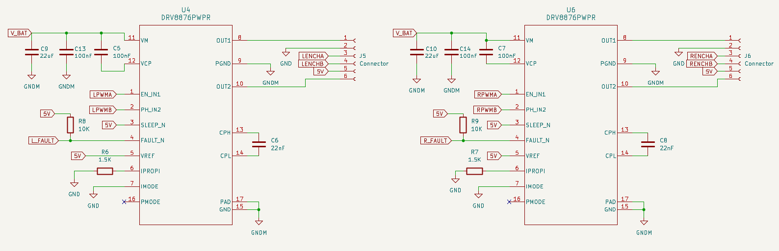
│   ├── Motor_Controller.kicad_sch # DRV8876 H-bridge drive stages
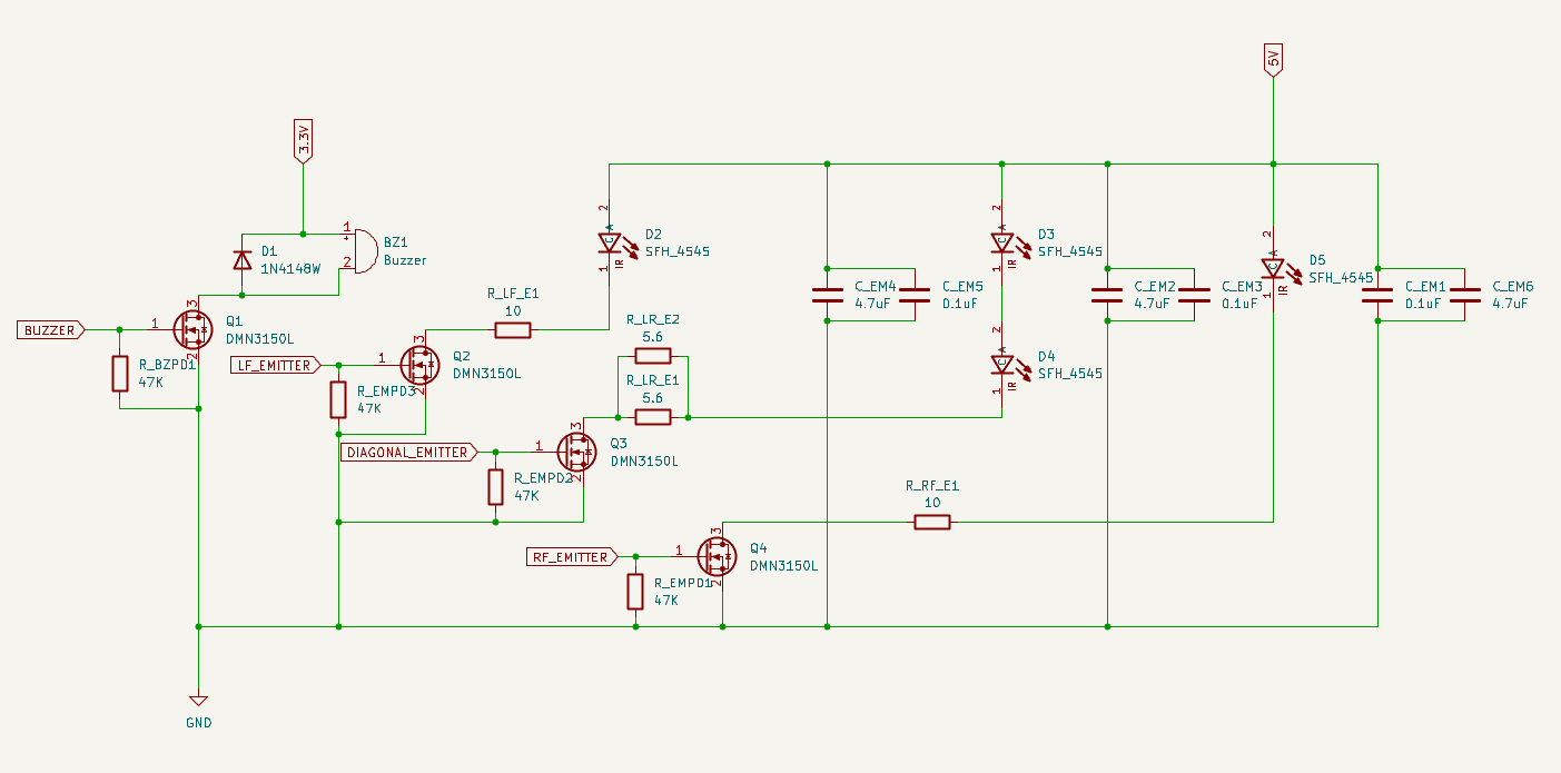
│   ├── Emitter_System.kicad_sch   # IR LED emitters for wall sensing
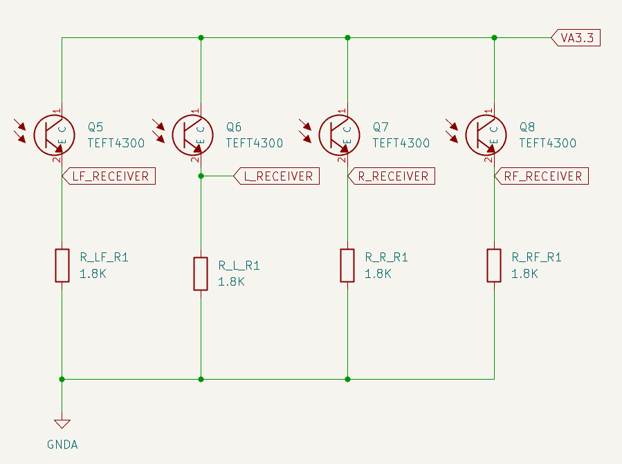
│   ├── Receiver_System.kicad_sch  # IR phototransistor receivers
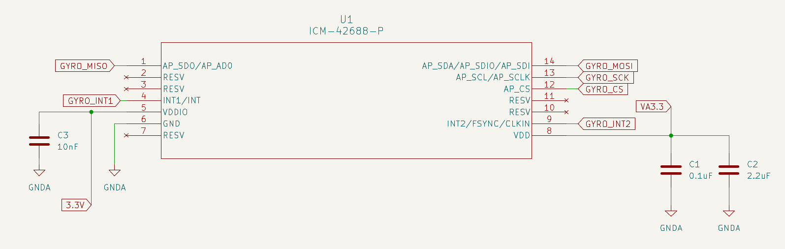
│   ├── gyro.kicad_sch             # IMU (ICM-42688-P)
│   ├── Mode_Indication_System.kicad_sch # Status LEDs + push buttons
│   └── Display.kicad_sch          # Display connector
├── LICENSE
└── README.md
Note:
firmware/andcad/directories will be added as those parts of the project come online (see Roadmap / Status).
Nova's electronics are laid out as a single hierarchical KiCad project (PCB_Kicad/untitled.kicad_pro), split into sub-sheets by subsystem so each part of the design — power, motor drive, sensing, control — can be reviewed and iterated on independently.
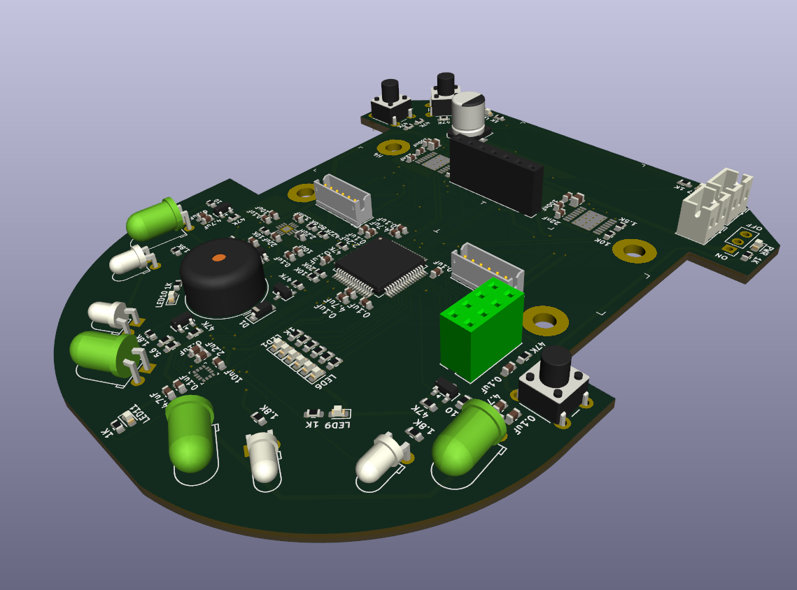
| Subsystem | Part | Purpose |
|---|---|---|
| Microcontroller | STM32G474RE (LQFP64) | Main flight computer — sensor fusion, maze-solving, motor control |
| Motor drivers | 3× DRV8876PWPR | H-bridge drivers for the drive motors |
| Wall sensors (emit) | 5× SFH 4545 IR LED | Infrared emitters for wall detection |
| Wall sensors (receive) | 5× TEFT 4300 phototransistor | Infrared receivers for wall detection |
| IMU | ICM-42688-P | 6-axis gyroscope + accelerometer for heading and slip detection |
| Buck converter | TLV62130RGTR | Steps battery voltage down to logic/motor rail |
| LDO regulator | TPS7A20xx | Clean low-noise rail for analog/sensor circuitry |
| Status UI | 12× LED, 4× push button | Mode selection and run-status indication |
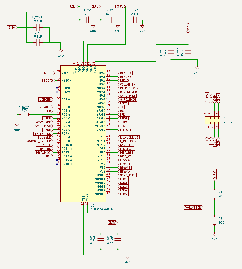
Nova is built around an STM32G474RE in an LQFP64 package, chosen for its combination of a fast Cortex-M4F core, hardware FPU, and rich set of timers/ADCs needed for closed-loop motor control and simultaneous IR sensor sampling.
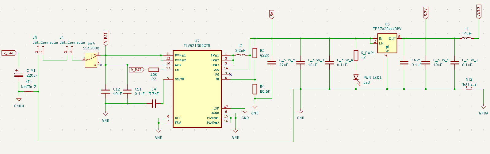
Power comes from an onboard battery via a JST connector, protected and conditioned through:
Three DRV8876PWPR H-bridge motor drivers provide current-controlled drive to the mouse's motors, with current-sense feedback routed back to the MCU's ADC for closed-loop speed/torque control.
Five SFH 4545 infrared LEDs, switched by DMN3150L MOSFETs, are pulsed to illuminate the maze walls immediately around the mouse without saturating the receivers or wasting battery power.
Five TEFT 4300 phototransistors, arranged around the front and sides of the mouse, detect the IR light reflected off maze walls and feed an analog signal back to the MCU — the core of Nova's wall-detection system.
An ICM-42688-P 6-axis IMU provides yaw-rate and acceleration data, used for precise turn control and to detect wheel slip during high-speed runs.
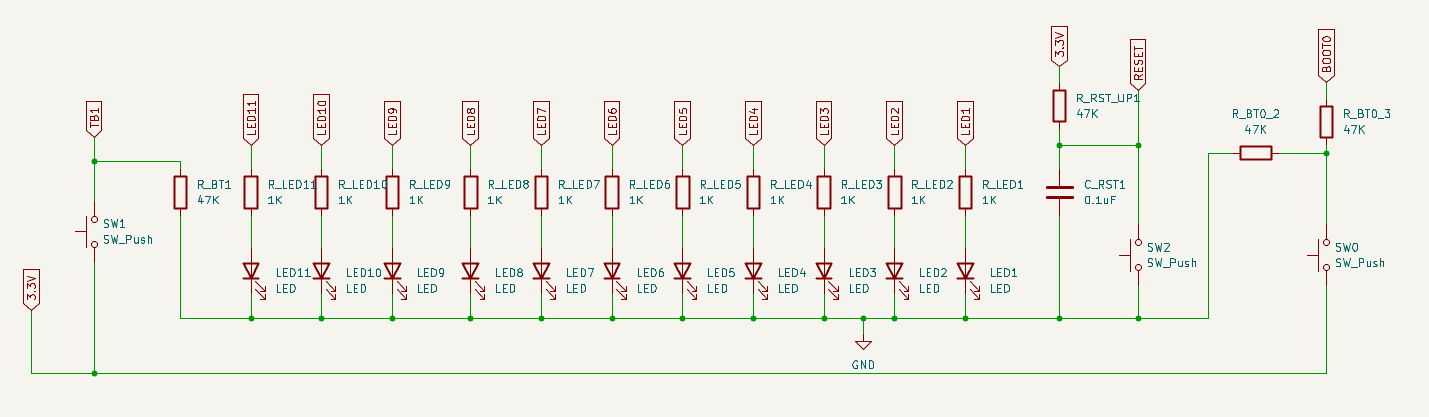
A bank of 12 LEDs and 4 push buttons lets the mouse indicate its current state (e.g. searching, ready, error) and lets the operator select a run mode or maze configuration without needing a host PC connection.
A 7-pin connector is broken out for an onboard display module (e.g. a small OLED), for showing maze-solving status and diagnostics on the mouse itself.
CAD design for the chassis, motor mounts, sensor mounts, and wheels has not yet been added to this repository.

Firmware (STM32 HAL/FreeRTOS, sensor drivers, maze-solving algorithm, motor control loops) has not yet been added to this repository. This section will be filled in with build instructions and a source layout once firmware development begins.
To open and edit the hardware design:
git clone https://github.com/<your-username>/Nova-Micromouse.gitPCB_Kicad/untitled.kicad_pro in KiCad.Distributed under the MIT License. See LICENSE for more information.
Christopher Awomolo — chrisjawomolo@gmail.com
Project Link: https://github.com//Nova-Micromouse
| Qty | Value | Footprint | References |
|---|---|---|---|
| 12 | 1K | Resistor_SMD:R_0603_1608Metric | R_LED1, R_LED2, R_LED3, R_LED4, R_LED5, R_LED6, R_LED7, R_LED8, R_LED9, R_LED10, R_LED11, R_PWR1 |
| 12 | LED | LED_SMD:LED_0603_1608Metric | LED1, LED2, LED3, LED4, LED5, LED6, LED7, LED8, LED9, LED10, LED11, PWR_LED1 |
| 10 | 0.1uF | Capacitor_SMD:C_0603_1608Metric | C_3.3V_2, C_3.3V_4, C_EM1, C_EM3, C_EM5, C_RST1, C_V5, C1, C11, CNR1 |
| 9 | 47K | Resistor_SMD:R_0603_1608Metric | R_BOOT1, R_BT0_2, R_BT0_3, R_BT1, R_BZPD1, R_EMPD1, R_EMPD2, R_EMPD3, R_RST_UP1 |
| 5 | 0.1uF | Capacitor_SMD:C_0805_2012Metric | C_V2, C_V3, C_V4, C_VA2, C_VA4 |
| 4 | 1.8K | Resistor_SMD:R_0603_1608Metric | R_L_R1, R_LF_R1, R_R_R1, R_RF_R1 |
| 4 | 100nF | Capacitor_SMD:C_0603_1608Metric | C5, C7, C9, C10 |
| 4 | 10K | Resistor_SMD:R_0603_1608Metric | R2, R5, R8, R9 |
| 4 | DMN3150L | Package_TO_SOT_SMD:SOT-23 | Q1, Q2, Q3, Q4 |
| 4 | MountingHole_Pad | MountingHole:MountingHole_3.2mm_M3_Pad_TopBottom | H1, H2, H3, H4 |
| 4 | SFH_4545 | LED_THT:LED_D5.0mm_Horizontal_O1.27mm_Z3.0mm | D2, D3, D4, D5 |
| 4 | TEFT4300 | LED_THT:LED_D3.0mm_Horizontal_O1.27mm_Z2.0mm_Clear | Q5, Q6, Q7, Q8 |
| 3 | 10uF | Capacitor_SMD:C_0603_1608Metric | C_3.3V_1, C_3.3V_3, C12 |
| 3 | 4.7uF | Capacitor_SMD:C_0603_1608Metric | C_EM2, C_EM4, C_EM6 |
| 3 | SW_Push | Button_Switch_THT:SW_PUSH_6mm_H7.3mm | SW0, SW1, SW2 |
| 2 | 1.5K | Resistor_SMD:R_0603_1608Metric | R6, R7 |
| 2 | 10 | Resistor_SMD:R_0603_1608Metric | R_LF_E1, R_RF_E1 |
| 2 | 22nF | Capacitor_SMD:C_0603_1608Metric | C6, C8 |
| 2 | 4.7uF | Capacitor_SMD:C_0805_2012Metric | C_VA1, C_VA3 |
| 2 | 5.6 | Resistor_SMD:R_0603_1608Metric | R_LR_E1, R_LR_E2 |
| 2 | Conn_01x06_Socket | Connector_JST:JST_ZH_B6B-ZR_1x06_P1.50mm_Vertical | J5, J6 |
| 2 | DRV8876PWPR | DRV8876:PWP0016J_L | U4, U6 |
| 2 | JST_Connector | Connector_JST:JST_PH_B2B-PH-K_1x02_P2.00mm_Vertical | J3, J4 |
| 1 | 10nF | Capacitor_SMD:C_0603_1608Metric | C3 |
| 1 | 10uH | Inductor_SMD:L_0603_1608Metric | L1 |
| 1 | 1N4148W | Diode_SMD:D_SOD-123 | D1 |
| 1 | 2.2uF | Capacitor_SMD:C_0603_1608Metric | C2 |
| 1 | 2.2uF | Capacitor_SMD:C_0805_2012Metric | C_VCAP1 |
| 1 | 2.2uH | Inductor_SMD:L_0603_1608Metric | L2 |
| 1 | 20K | Resistor_SMD:R_0603_1608Metric | R1 |
| 1 | 220uF | Capacitor_SMD:CP_Elec_8x6.5 | C_M1 |
| 1 | 22uF | Capacitor_SMD:C_0603_1608Metric | C_3.3V_5 |
| 1 | 3.3nF | Capacitor_SMD:C_0603_1608Metric | C4 |
| 1 | 422K | Resistor_SMD:R_0603_1608Metric | R3 |
| 1 | 80.6K | Resistor_SMD:R_0603_1608Metric | R4 |
| 1 | Buzzer | Buzzer_Beeper:Buzzer_TDK_PS1240P02BT_D12.2mm_H6.5mm | BZ1 |
| 1 | Conn_01x07_Socket | Connector_PinSocket_2.54mm:PinSocket_1x07_P2.54mm_Vertical | J2 |
| 1 | Conn_02x04_Odd_Even | Connector_PinSocket_2.54mm:PinSocket_2x04_P2.54mm_Vertical | J8 |
| 1 | ICM-42688-P | ICM-42688:LGA14_2P5X3X0P91_TDK | U1 |
| 1 | SS12D00 | SS12D00:PinHeader_1x03_P2.54mm_Vertical | SW4 |
| 1 | STM32G474RETx | Package_QFP:LQFP-64_10x10mm_P0.5mm | U3 |
| 1 | TLV62130RGTR | TLV62130RGTR:QFN50P300X300X100-17N | U7 |
| 1 | TPS7A20xxxDBV | Package_TO_SOT_SMD:SOT-23-5 | U5 |
UBIEEE/FrankenMouse
FrankenMouse is a MicroMouse robot that was designed, built, and programmed from scratch by members of the University at Buffalo's IEEE Student Branch.


vorlaxen-labs/AratMicro
High-performance, open-source micromouse robot platform built for Robosam and MEB Robot (Ministry of National Education Robotics Competition, Turkey).


Maahi-V/26-27-UCI-Kit-Micromouse
Kit Mouse Schematic and Layout for the 2026-27 Micromouse IEEE program

RoboJackets/roboracing-micromouse-pcb
This year, we are making Ratatouillii! 🐭🔥

It measures 82 × 100 mm and has 4 copper layers, 1.6 mm thick.
121 parts, built around the TLV62130RGTR, ICM-42688-P, DMN3150L and SFH 4545. The full list of its parts is on this page, with links to each part's symbol and footprint where PCBKit's library has them.
From the ChristopherAwomolo/Nova-Micromouse repository on GitHub, at the commit this page was made from: the board is PCB_Kicad/untitled.kicad_pcb and its schematic PCB_Kicad/Display.kicad_sch. PCBKit opens the board in the browser, with nothing to install.
Its repository publishes it under the MIT licence: you may reuse it on that licence's terms (keep the author's notice, and for a copyleft licence share your changes alike).