4 layers140.3 × 89.5 mm
Strain guage
ttosu25/SG-3
Hardware design for a mixed-signal strain-data acquisition system, incorporating sensor excitation, analogue signal conditioning, ADC, and MCU interface
93 parts

 ttosu25/SG-3
Hardware design for a mixed-signal strain-data acquisition system, incorporating sensor excitation, analogue signal conditioning, ADC, and MCU interface
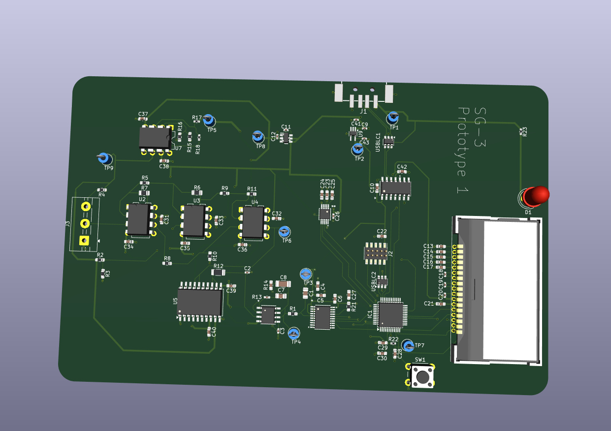
Strain guage r0 is an open-source printed circuit board by ttosu25, from the ttosu25/SG-3 repository on GitHub. It is a 4-layer board of 132.7 × 89.5 mm with 97 parts on 124 nets, routed with 774 tracks and 119 vias.
It is built around the STM32C091CBT6, AD630ARZ and MCP2221A-I/SL, with the MCP3561-E/ST, OP177GPZ and AD9833BRMZ among its other parts. Its parts include 43 capacitors, 21 resistors, 12 ICs, 3 connectors and 1 diode. It belongs with the sensors and measurement boards and the STM32 boards of this library.


Strain gauges produce very small differential voltage signals that encode information about mechanical strain. Precise and accurate measurement requires careful analogue signal conditioning before digitisation, followed by digital signal processing to extract the desired measurement. This project explores the design of a complete measurement device, from sensor excitation and analogue front-end conditioning through to digital acquisition, processing, and display output.
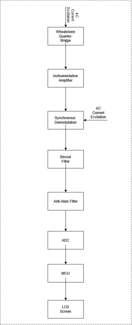
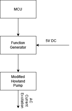
Current-driven AC excitation: Current excitation improves the linearity between applied strain and differential bridge output. Using AC rather than DC excitation reduces measurement offset and drift, mitigates low frequency (1/f) noise, and suppresses parasitic thermoelectric effects.
The Bessel response was selected for its absence of overshoot and steeper amplitude roll-off compared with the Butterworth response. The filter also exhibits minimal passband variation and a simulated settling time of 7 ms, which is significantly shorter than the latency introduced by the sigma-delta ADC's digital filtering.
Sigma-Delta converters contain integrated features such as digital filters that minimise the effect of extrinsic and intrinsic noise sources such as alias signal noise, 50/60hz power noise, RF noise pick up and clock jitter. The Oversampling nature of Sigma-Delta converts also distributes noise over a wider range of frequencies which reduces the effect of quantisation noise.
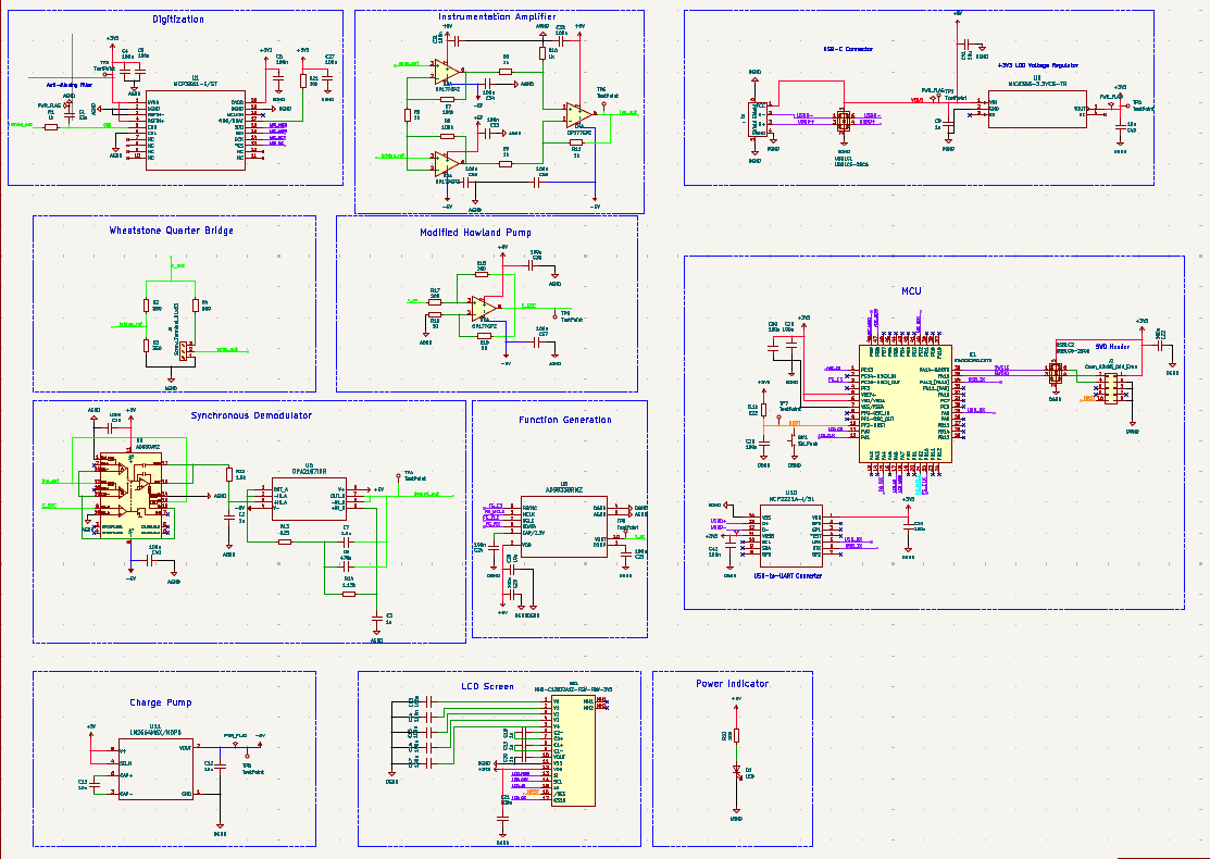
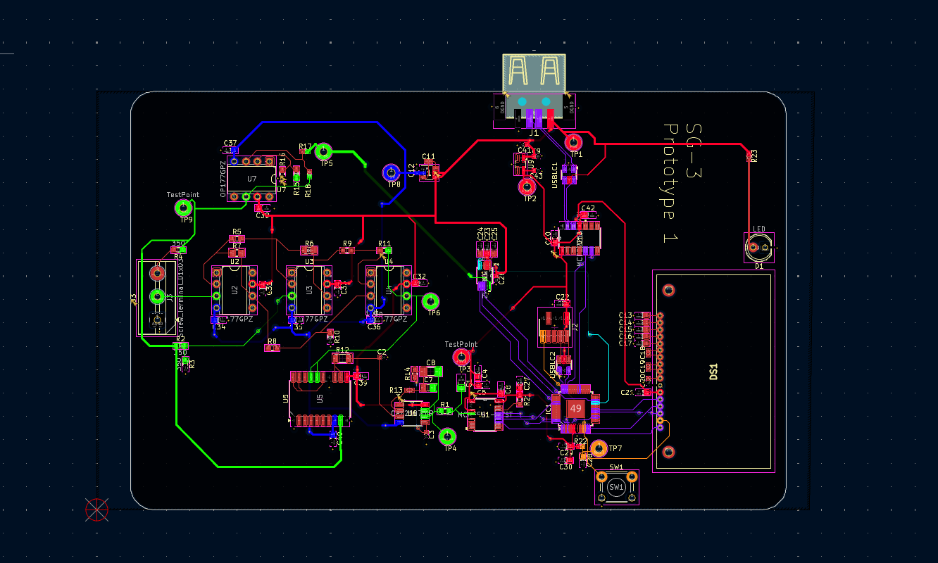
hardware/ — Contains the schematics, PCB layout files, Gerber files, MCU pin assignment, and hardware revisions.
tr/ — Contains technical research and supporting analysis, including datasheets, application notes, initial problem-space exploration, and SPICE simulations with FFT analysis.
docs/ — Contains the project specification, design documentation, and system diagrams.
firmware/ — Contains the programs running on the MCU for the embedded application.
Logbook entries not available.
Prototyping Stage, PCB fabricated.
| Qty | Value | Footprint | References |
|---|---|---|---|
| 29 | 100n | Capacitor_SMD:C_0603_1608Metric_Pad1.08x0.95mm_HandSolder | C10, C13, C14, C15, C16, C17, C21, C22, C23, C24, C25, C27, C28, C29, C30, C31 +13 |
| 9 | TestPoint | TestPoint:TestPoint_Loop_D2.54mm_Drill1.5mm_Beaded | TP1, TP2, TP3, TP4, TP5, TP6, TP7, TP8, TP9 |
| 6 | 1k | Resistor_SMD:R_0603_1608Metric_Pad0.98x0.95mm_HandSolder | R1, R5, R8, R9, R10, R11 |
| 6 | 1u | Capacitor_SMD:C_0402_1005Metric | C2, C3, C9, C18, C19, C20 |
| 5 | 10u | Capacitor_SMD:C_0402_1005Metric | C11, C12, C26, C41, C43 |
| 4 | MountingHole_Pad | MountingHole:MountingHole_3.2mm_M3_ISO7380_Pad | H1, H2, H3, H4 |
| 4 | OP177GPZ | Package_SO:SOIC-8_5.3x5.3mm_P1.27mm | U2, U3, U4, U7 |
| 3 | 200 | Resistor_SMD:R_0402_1005Metric_Pad0.72x0.64mm_HandSolder | R17, R18, R23 |
| 3 | 350 | Resistor_SMD:R_0603_1608Metric_Pad0.98x0.95mm_HandSolder | R2, R3, R4 |
| 2 | 100k | Resistor_SMD:R_0805_2012Metric_Pad1.20x1.40mm_HandSolder | R6, R7 |
| 2 | 50 | Resistor_SMD:R_0603_1608Metric_Pad0.98x0.95mm_HandSolder | R15, R16 |
| 2 | USBLC6-2SC6 | Package_TO_SOT_SMD:SOT-23-6 | USBLC1, USBLC2 |
| 1 | 1.15k | Capacitor_SMD:C_0603_1608Metric_Pad1.08x0.95mm_HandSolder | R14 |
| 1 | 1.5k | Resistor_SMD:R_1206_3216Metric | R12 |
| 1 | 1.5u | Capacitor_SMD:C_0805_2012Metric_Pad1.18x1.45mm_HandSolder | C7 |
| 1 | 10k | Resistor_SMD:R_0603_1608Metric_Pad0.98x0.95mm_HandSolder | R21 |
| 1 | 33n | Capacitor_SMD:C_0805_2012Metric_Pad1.18x1.45mm_HandSolder | C1 |
| 1 | 470n | Capacitor_SMD:C_1206_3216Metric_Pad1.33x1.80mm_HandSolder | C8 |
| 1 | 5.1k | Resistor_SMD:R_0201_0603Metric | R22 |
| 1 | 825 | Capacitor_SMD:C_0402_1005Metric_Pad0.74x0.62mm_HandSolder | R13 |
| 1 | AD630ARZ | Package_SO:SOIC-20W_7.5x12.8mm_P1.27mm | U5 |
| 1 | AD9833BRMZ | AD9833BRMZ:RM_10_ADI | U8 |
| 1 | Conn_02x05_Odd_Even | Connector_PinHeader_1.27mm:PinHeader_2x05_P1.27mm_Vertical_SMD | J2 |
| 1 | LED | LED_THT:LED_D5.0mm | D1 |
| 1 | LM2664M6X/NOPB | LM2664:DBV0006A_N | U11 |
| 1 | MCP2221A-I/SL | MCP2221A-I-SL:SOIC14_SL_MCH | U10 |
| 1 | MCP3561-E/ST | MCP3561:TSSOP20_ST_MCH | U1 |
| 1 | MIC5365-3.3YC5-TR | Package_TO_SOT_SMD:TSOT-23-5 | U9 |
| 1 | NHD-C12832A1Z-FSW-FBW-3V3 | NHD-C12832A1Z-FSW-FBW-3V3:NHDC12832A1ZFSWFBW3V3 | DS1 |
| 1 | OPA2187IDR | OPA2187:D8_TEX | U6 |
| 1 | STM32C091CBT6 | Package_QFP:LQFP-48-1EP_7x7mm_P0.5mm_EP3.6x3.6mm | IC1 |
| 1 | SW_Push | Button_Switch_THT:SW_PUSH_6mm | SW1 |
| 1 | Screw_Terminal_01x03 | TerminalBlock:TerminalBlock_MaiXu_MX126-5.0-03P_1x03_P5.00mm | J3 |
| 1 | ~ | USBC:BX-TYPE-A-MWT4P | J1 |
ttosu25/SG-3
Hardware design for a mixed-signal strain-data acquisition system, incorporating sensor excitation, analogue signal conditioning, ADC, and MCU interface


misko/prompt2device
The separate vNext PCB skill and orchestrator package is available alongside the reference workflow below; existing projects keep their accepted toolchain until an explicit migration.


jayis1/hardware-design-lab
Full-cycle hardware device designs — each device in its own subfolder with architecture, schematics, PCB layout, and software stack


GhanGhan/SurvBot
Remote controlled robot that surveys the environment it is travelling in

Alberta2514640/EIT-Machine
Arbitrary Waveform Generator for the Raspberry Pi Pico 16 Channels

It measures 132.7 × 89.5 mm and has 4 copper layers, 1.6 mm thick.
97 parts, built around the STM32C091CBT6, AD630ARZ, MCP2221A-I/SL and MCP3561-E/ST. The full list of its parts is on this page, with links to each part's symbol and footprint where PCBKit's library has them.
From the ttosu25/SG-3 repository on GitHub, at the commit this page was made from: the board is hardware/strain_guage_PCB/revisions/strain_guage_r0.kicad_pcb and its schematic hardware/strain_guage_PCB/strain_guage.kicad_sch. PCBKit opens the board in the browser, with nothing to install.
Its repository states no licence, so its author keeps all rights: ask ttosu25 before reusing the design.