4 layers60 × 102 mm
Anthracite top
trope-oshw/anthracite
MIDI-controllable fuzz pedal: open hardware (CERN-OHL-S-2.0), firmware (GPL-3.0-or-later)
222 parts5CERN-OHL-S-2.0

 trope-oshw/anthracite5
MIDI-controllable fuzz pedal: open hardware (CERN-OHL-S-2.0), firmware (GPL-3.0-or-later)
Anthracite bottom is an open-source printed circuit board by trope-oshw, from the trope-oshw/anthracite repository on GitHub, published under the CERN-OHL-S-2.0 licence. It is a 4-layer board of 60 × 73.5 mm with 224 parts on 154 nets, routed with 1,622 tracks and 515 vias.
It is built around the STM32F030C8T6, SN74LVC1G66DCKR-MS and 78L05G-AB3-R, with the M24C64-RMN6TP, SN74HCT04DR (LX) and XC6206P332MR-G among its other parts. Its parts include 107 resistors, 53 capacitors, 24 diodes, 12 transistors and 10 ICs. It belongs with the audio and music boards and the STM32 boards of this library.


A MIDI-controllable analogue fuzz pedal.
Fuzz pedals are awkward to live with: the sound changes when you swap guitars, a wah in front of one loses its range, and few switchers can drive one. Most of that traces back to a single cause — the input impedance of a fuzz is low, and it is fixed. Anthracite lets you choose the load your pickup sees, and keeps the whole signal path analogue: it is switched by analogue switches rather than mechanical contacts, and the microcontroller only moves those switches and never touches the audio.
Designed and built by Trope (山本回路設計).
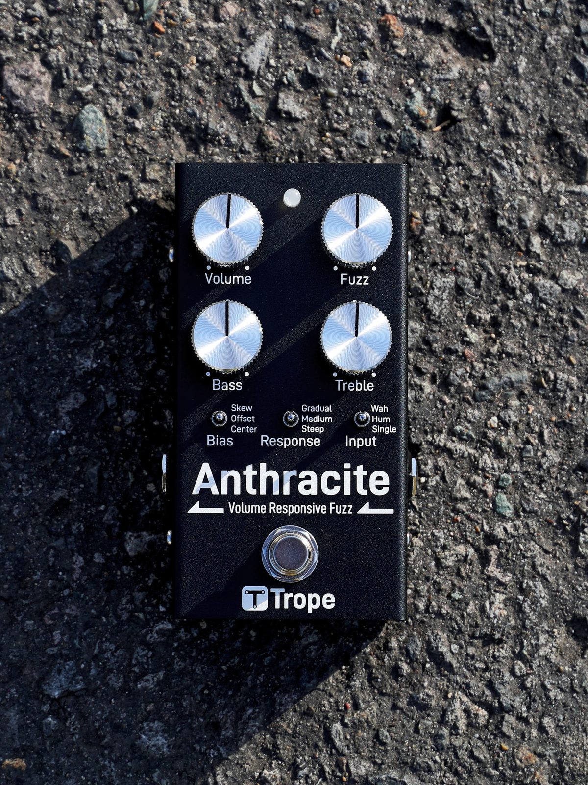
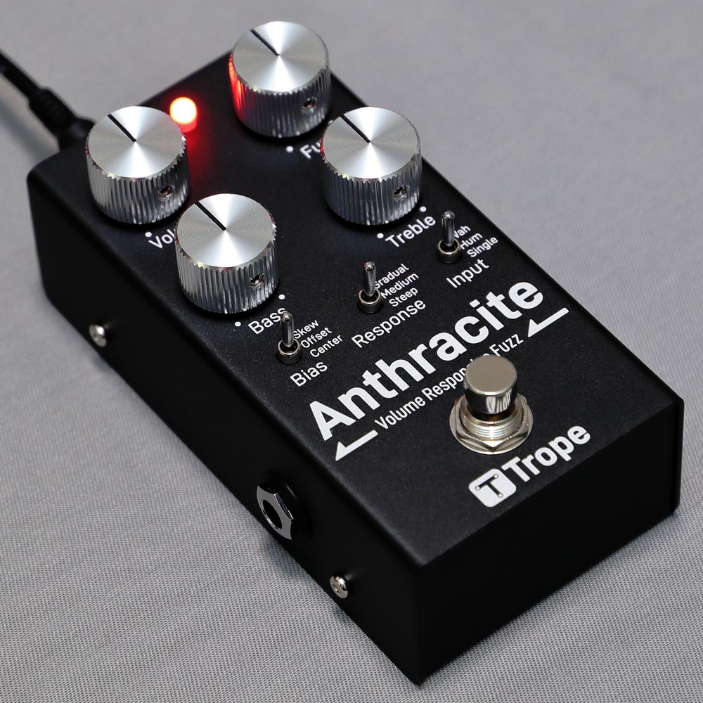 | 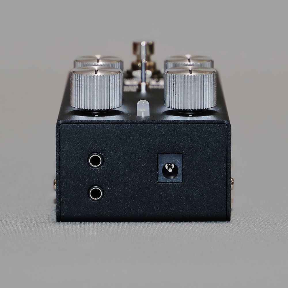 | 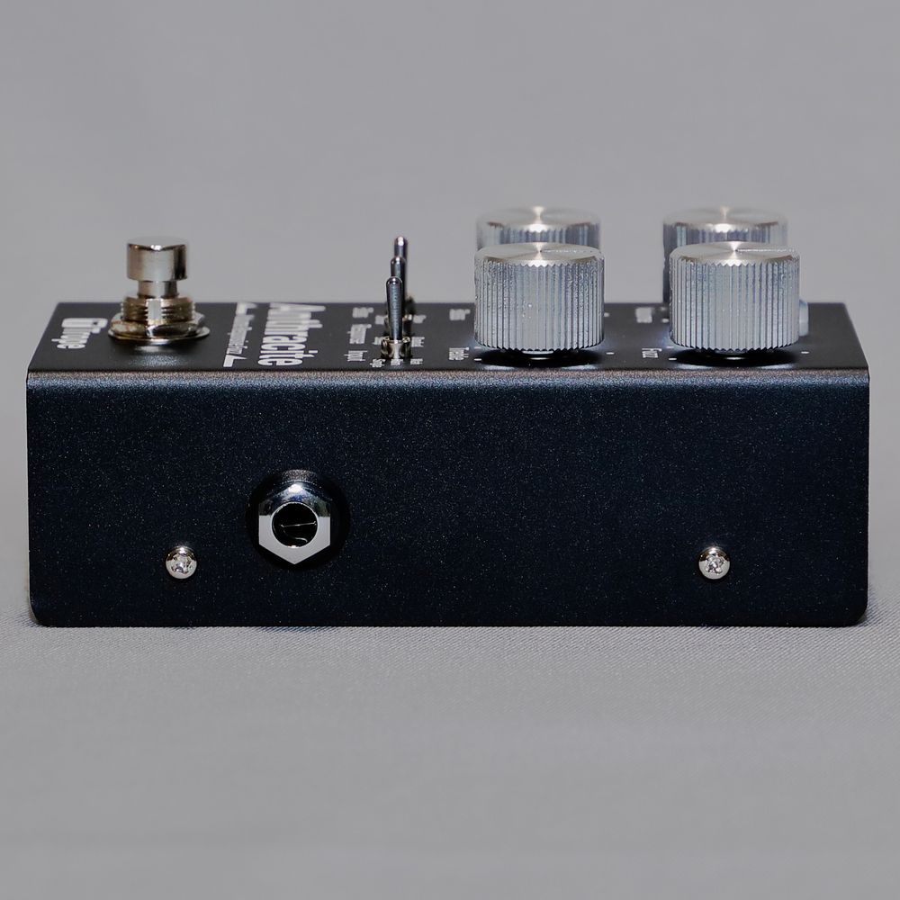 |
| Angled view, LED lit | Top edge: MIDI IN / OUT (3.5 mm TRS) and 9 V DC | Input side: 1/4" jack |
| Power | 9 V DC, centre-negative, 5.5 / 2.1 mm barrel. No battery compartment |
| Operating voltage | 8.4 – 11.5 V |
| Recommended operating voltage | 8.6 – 10.0 V |
| Current draw | About 70 mA at 9 V with the effect on (measured 67 – 74 mA depending on settings; about 4 mA less in bypass) |
| Adapter rating | 200 mA or more |
| Input impedance | About 13 kΩ (Single) / 24 kΩ (Hum) / 44 kΩ (Wah) at 1 kHz, effect on |
| Input impedance, bypassed | About 1 MΩ from 100 Hz to 1 kHz, measured |
| Output impedance | About 1 kΩ at 1 kHz |
| Bypass | Buffered. Switched electronically — no mechanical contacts in the audio path |
| MIDI | 3.5 mm TRS, MIDI Type-A, 31250 baud. MIDI IN, and a MIDI OUT (Thru) jack that doubles as an external-switch input |
| Microcontroller | STM32F030C8T6 (Cortex-M0, 48 MHz, LQFP48) |
| Enclosure | 73.5 (W) × 57.5 (H) × 128 (D) mm including knobs and jacks, 268 g |
The pedal monitors its supply and flashes the LED if the voltage drops below about 8 V or rises above about 12 V. The exact trip points vary slightly from unit to unit, but the warning does not appear inside the operating voltage range. Do not run the pedal outside that range even if no warning is shown.
The effect-on input impedance figures come from a SPICE model of the input circuit and agree with measurements on a v1.0 unit. The impedance stays roughly flat at low frequencies (about 24 / 34 / 55 kΩ at 20 Hz) and falls gradually towards high frequencies. That roll-off is deliberate: a heavier load pulls the pickup's resonant peak lower, and the Input switch selects between three loads.
| Board | Size | Layers | Copper |
|---|---|---|---|
| Top (analogue) | 60 × 102 mm | 4 | 35 µm (1 oz) outer, 17.5 µm (0.5 oz) inner |
| Bottom (control) | 60 × 73.5 mm | 4 | 35 µm (1 oz) outer, 17.5 µm (0.5 oz) inner |
| Footswitch | 14 × 16.15 mm | 2 | — |
All boards are 1.6 mm FR-4.
Four potentiometers and three three-position toggles.
| Control | Range |
|---|---|
| Volume | 50 kΩ, log (A taper) |
| Fuzz | 10 kΩ, reverse log (C taper), wired as a variable resistor. Roughly 39 dB to 65 dB of small-signal gain in the fuzz stage |
| Bass | 20 kΩ, linear (B taper). Low shelf: up to about −25 dB of cut and +13 dB of boost at 20 Hz. The half-way point moves between about 170 Hz and 390 Hz with the knob |
| Treble | 20 kΩ, linear (B taper). High shelf: up to about −26 dB of cut and +14 dB of boost at 10 kHz. The half-way point moves between about 700 Hz and 1.7 kHz, so it also acts on the midrange around 1 kHz |
Toggle positions are listed from top to bottom.
| Toggle | Positions | What it changes |
|---|---|---|
| Bias | Skew / Offset / Center | Operating point of the output-side fuzz transistor (3:1, 2:1, 1:1). More asymmetry means more even-order harmonics and less gain. Second harmonic moves from −16.7 dBc (Center) to −9.5 dBc (Skew) at 400 Hz / 0.1 Vpp, Fuzz 50 %. With DIP-SW2 on, the toggle selects X-Skew (4:1) / Skew / Offset instead |
| Response | Gradual / Medium / Steep | Series resistance at the fuzz input, which sets how abruptly the pedal cleans up as you roll back the guitar volume. THD at 400 Hz / 1 Vpp, Fuzz 50 %: 65.6 % / 59.7 % / 49.3 % |
| Input | Wah / Hum / Single | Input filter, which sets the loading your pickup sees (see the impedance figures above) |
The pedal receives; it never sends control messages of its own. MIDI IN is active whichever way DIP-SW3 (MIDI mode / external-switch mode) is set.
| CC | Function | Values |
|---|---|---|
| 81 | Bypass / engage (channel 12, with DIP-SW4 off as shipped) | ≥ 64 engages, < 64 bypasses |
| 83 | Input | 0 = return to the physical toggle · 1–31 Single · 32–63 Hum · 64–95 Wah · 96–127 All-OFF (input filter disconnected) |
| 84 | Response | 0 = return to the toggle · 1–31 Steep · 32–63 Medium · 64–95 Gradual · 96–127 no change |
| 85 | Bias | 0 = return to the toggle · 1–31 Center · 32–63 Offset · 64–95 Skew · 96–127 X-Skew |
CC 83/84/85 are received on the same channel as the bypass / engage message. Sending 0 to any of them hands control back to the physical toggle, so a MIDI override never becomes something you cannot undo from the panel.
MIDI-Learn stores a channel and CC number for the bypass function in EEPROM; with DIP-SW4 on, the pedal uses them instead of channel 12 / CC 81. Units ship with channel 6 / CC 1 already stored. Many MIDI foot controllers send their expression pedal on CC 1, so with DIP-SW4 on, an expression pedal on channel 6 will switch the effect as it crosses value 64; learn a different CC or change the controller's CC. If nothing is stored, DIP-SW4 on disables MIDI control entirely rather than falling back to channel 12 / CC 81. Do not learn CC 83, 84 or 85. Active Sensing (0xFE) is emitted about every 250 ms, and received messages are passed through to MIDI OUT unmodified, both only in MIDI mode (DIP-SW3 on, as shipped). With DIP-SW3 off, the MIDI OUT jack becomes an external footswitch input.
hardware/     KiCad projects for the three circuit boards (top, bottom and
              footswitch) and the front-panel artwork, with the symbol and
              footprint libraries they use; parts list (parts.md)
enclosure/    Enclosure 3D model (STEP), hole-layout and assembly drawings
              (PDF), front-panel artwork for laser marking (DXF, SVG, PNG)
firmware/     STM32 firmware source: STM32CubeMX project, CMake build, the
              ST HAL and CMSIS, and the build and flashing guide
docs/         Schematics (PDF, plus a PNG of each sheet), bills of materials
              (CSV), 3D models of the assembled boards (STEP), product photos
The STEP model and the drawings (PDF, DXF) are the reference for the enclosure.
Gerbers and the ordering notes are attached to each
release rather than kept in
the tree, so that what you download always matches a specific version. There is
no assembler-specific BOM or pick-and-place file: build them from
docs/bom/bom-*.csv and the KiCad projects for whoever assembles your boards.
The user manual, measured data, and circuit explanations live at https://docs.trope-oshw.org — they are not duplicated here.
The KiCad projects need KiCad 10 or later. They are self-contained: every
custom symbol and footprint is in the project's own libs/ directory, so you
can clone this repository and open them without installing anything else.
hardware/parts.md lists the parts chosen for each board,
with manufacturer part numbers and LCSC numbers.
Ordering parameters used for the production run are recorded in
ordering-notes.md attached to each release. They matter, because a different
stackup or copper weight gives a different board.
The full source is in firmware/. Built as described in
firmware/README.md, it reproduces the image on shipped
units byte for byte; that file gives the toolchain versions, the SHA-256 of the
image, and how to write it to a finished unit. You do not need to touch the
firmware to use the pedal; the instructions are there because being able to
replace the software on hardware you own is part of what this licence is for.
| What | Licence |
|---|---|
Hardware (hardware/, enclosure/) | CERN-OHL-S-2.0 |
Firmware (firmware/), except the third-party code below | GPL-3.0-or-later |
Generated design documents (docs/: schematics, bills of materials, board 3D) | CERN-OHL-S-2.0 |
Product photographs (docs/images/) | CC-BY-SA-4.0 |
| Text (this README, CHANGELOG, ERRATA, CONTRIBUTING) | CC-BY-SA-4.0 |
Full texts are in LICENSES/; per-file assignments are declared in
REUSE.toml following the REUSE
specification. See COPYRIGHT.txt for the notices.
Parts of the firmware come from STMicroelectronics and Arm and keep their own
licences: the STM32F0 HAL driver and the code generated by STM32CubeMX are
BSD-3-Clause, and the CMSIS headers and ST's CMSIS device files are Apache-2.0.
Likewise, some footprints in hardware/*/libs/ are derived from the KiCad
standard libraries and stay under CC-BY-SA-4.0 with the KiCad libraries
exception. The symbol libraries mix symbols derived the same way with symbols
drawn for this project, so both licences apply to them; REUSE.toml lists the
files.
The design files in this repository are open source under the licences above. The Trope and 山本回路設計 brand names, the Trope logo, and the product name "Anthracite" are not. They are trademarks of 山本回路設計 and are not licensed to you by any of the licences here. See also section 8.2 of the CERN-OHL-S v2.
You are free to build, modify, and sell hardware derived from these files. When you do, please give it your own name and your own branding. A modified version could be called "Foobar Audio — Charcoal Fuzz"; it should not be called "Anthracite" or "Trope Anthracite".
You may state truthfully that your product is based on the Anthracite design by Trope. You may not use the Trope logo, or a name so close to Trope or Anthracite that a buyer could confuse the two.
All Trope branding has been removed from the published files, both the
panel artwork and the circuit-board silkscreen, so hardware made from these
files carries no Trope marks by default. Please keep it that way. Instead of a
product name, the top and bottom boards carry the board version (V1.0), the
licence (CERN-OHL-S-2.0) and where the source lives
(github.com/trope-oshw/anthracite).
Boards from the first production run carry Anthracite V1.0 on the silkscreen
instead. That text is the only difference: electrically they are the same as the
published boards. Units built by Trope after that run use the published board
files as they are.
Questions, or a request to use the marks: trope.oshw@gmail.com — ask first and the answer is almost always yes.
The product and the boards carry a vMAJOR.MINOR number, silkscreened on the
PCB. The firmware carries its own semantic version. They move independently:
fixing a firmware bug does not change the boards, so the board version stays put.
See CHANGELOG.md for what changed in each release, and ERRATA.md for problems found in hardware that has already been built. If your unit behaves differently from this documentation, check the errata first.
Anthracite is on sale. Trope builds and tests each unit and ships it with its own test report. The product page at https://trope-oshw.org/anthracite/ shows the current price and takes orders. Trope plans to publish the cost breakdown and the formula behind the price at https://docs.trope-oshw.org. Questions go to trope.oshw@gmail.com.
Buying one is what pays for the next design being opened.
Issues are welcome; pull requests to the hardware are not, for reasons explained in CONTRIBUTING.md. Firmware and documentation PRs are welcome.
This design is distributed as-is, with no warranty of any kind, express or implied, including merchantability and fitness for a particular purpose. See sections 6.1 and 6.2 of the CERN-OHL-S v2 for the full disclaimer.
If you build, modify, or sell hardware based on these files, you are the manufacturer of that hardware. You alone are responsible for its safety and for its compliance with every regulation that applies where you place it on the market. Any certification, testing, or conformity marking obtained by 山本回路設計 applies only to units built and sold by 山本回路設計, and does not transfer to your build.
Use a regulated, correctly-polarised 9 V DC supply. Incorrect power can damage the pedal and whatever is connected to it.
| Qty | Value | Footprint | References |
|---|---|---|---|
| 29 | 10k | anthracite:R_0402_1005Metric_MiniFont | R105, R106, R109, R119, R120, R121, R122, R125, R126, R138, R141, R202, R203, R302, R1002, R1003 +13 |
| 27 | 22k | anthracite:R_0402_1005Metric_MiniFont | R204, R205, R207, R304, R305, R307, R404, R405, R407, R504, R505, R507, R604, R1004, R1005, R1007 +11 |
| 19 | 0.1u | Capacitor_SMD:C_0603_1608Metric | C123, C124, C125, C127, C128, C129, C130, C131, C132, C133, C134, C135, C136, C137, C138, C140 +3 |
| 19 | 3k3 | anthracite:R_0402_1005Metric_MiniFont | R115, R116, R117, R118, R127, R130, R139, R140, R142, R143, R201, R301, R401, R501, R601, R1001 +3 |
| 19 | LED(RED) | anthracite:D_0603_1608Metric_Name | D101, D103, D106, D108, D110, D111, D112, D113, D114, D115, D201, D301, D401, D501, D601, D1001 +3 |
| 9 | 0.022u | Capacitor_SMD:C_0603_1608Metric | C201, C301, C401, C501, C601, C701, C801, C901, C1001 |
| 9 | 1u | Capacitor_SMD:C_0805_2012Metric | C101, C103, C112, C113, C115, C116, C117, C118, C120 |
| 9 | 33k | anthracite:R_0402_1005Metric_MiniFont | R206, R306, R406, R506, R606, R706, R806, R906, R1006 |
| 9 | MMDT2227 | Package_TO_SOT_SMD:SOT-363_SC-70-6 | Q201, Q301, Q401, Q501, Q601, Q701, Q801, Q901, Q1001 |
| 5 | 1k5 | Resistor_SMD:R_0402_1005Metric | R104, R134, R135, R136, R137 |
| 5 | TestPoint | anthracite:TestPoint_Pad_1.5x1.5mm_Label | TP106, TP107, TP115, TP117, TP120 |
| 4 | 100u | anthracite:CP_Rubycon_35TZV100M6.3X8 | C104, C109, C114, C121 |
| 4 | 1N5819WS | Diode_SMD:D_SOD-323 | D102, D104, D105, D107 |
| 3 | 2.2k | Resistor_SMD:R_0603_1608Metric | R101, R107, R113 |
| 3 | 3k3 | Resistor_SMD:R_0402_1005Metric | R103, R133, R144 |
| 3 | SN74LVC1G66DCKR | Package_TO_SOT_SMD:SOT-353_SC-70-5 | U108, U109, U110 |
| 2 | 0.1u | Capacitor_SMD:C_0805_2012Metric | C107, C111 |
| 2 | 0.47u | Capacitor_SMD:C_0603_1608Metric | C106, C110 |
| 2 | 100p | Capacitor_SMD:C_0603_1608Metric | C139, C141 |
| 2 | 10u | Capacitor_SMD:C_0805_2012Metric | C105, C108 |
| 2 | 120 | anthracite:R_0402_1005Metric_MiniFont | R131, R132 |
| 2 | 1k | anthracite:R_0402_1005Metric_MiniFont | R124, R129 |
| 2 | 33 | anthracite:R_0402_1005Metric_MiniFont | R114, R123 |
| 2 | 4.7u | Capacitor_SMD:C_0805_2012Metric | C122, C126 |
| 2 | 47u | anthracite:CP_Rubycon_35TZV100M6.3X8 | C102, C119 |
| 2 | 6.8k | Resistor_SMD:R_0603_1608Metric | R102, R108 |
| 2 | L78L05_SOT89 | Package_TO_SOT_SMD:SOT-89-3 | U101, U102 |
| 2 | MountingHole_Pad | MountingHole:MountingHole_3.2mm_M3_DIN965_Pad | H101, H102 |
| 2 | SS8050 | Package_TO_SOT_SMD:SOT-23 | Q101, Q103 |
| 2 | SW_SPST | anthracite:TS1088AR02016 | SW101, SW103 |
| 1 | 10k | Resistor_SMD:R_0603_1608Metric | R110 |
| 1 | 220 | anthracite:R_0402_1005Metric_MiniFont | R128 |
| 1 | 3.3k | Resistor_SMD:R_0603_1608Metric | R111 |
| 1 | 470 | Resistor_SMD:R_0603_1608Metric | R112 |
| 1 | B3B-PH-K-S | Connector_JST:JST_PH_B3B-PH-K_1x03_P2.00mm_Vertical | J102 |
| 1 | B6B-ZR-3.4(LF)(SN) | Connector_JST:JST_ZH_B6B-ZR_1x06_P1.50mm_Vertical | J107 |
| 1 | BAV99 | Package_TO_SOT_SMD:SOT-23 | D109 |
| 1 | BLM18PG121SN1D | Inductor_SMD:L_0603_1608Metric | FB101 |
| 1 | Conn_ST_STDC14 | anthracite:STDC14_2x07_P1.27mm_Vertical_ST-LINKV3 | J101 |
| 1 | KSD42 | Package_DIP:DIP-8_W7.62mm | SW102 |
| 1 | M24C64-RMN6TP | Package_SO:SOIC-8_3.9x4.9mm_P1.27mm | U106 |
| 1 | MJ-8435 | anthracite:MJ-8435 | J104 |
| 1 | NJW4191M | anthracite:DMP-8_P1.27mm_HandSolder | U104 |
| 1 | PH-2x10SG | Connector_PinHeader_2.54mm:PinHeader_2x10_P2.54mm_Vertical | J103 |
| 1 | PH-2x4SG | Connector_PinHeader_2.54mm:PinHeader_2x04_P2.54mm_Vertical | J105 |
| 1 | PH11-2x10SAG | Connector_PinHeader_1.27mm:PinHeader_2x10_P1.27mm_Vertical | J106 |
| 1 | SN74HCT04DR | Package_SO:SOIC-14_3.9x8.7mm_P1.27mm | U107 |
| 1 | SS8550 Y2 | Package_TO_SOT_SMD:SOT-23 | Q102 |
| 1 | STM32F030C8T6 | Package_QFP:LQFP-48_7x7mm_P0.5mm | U105 |
| 1 | XC6206P332MR-G | Package_TO_SOT_SMD:SOT-23-3 | U103 |
trope-oshw/anthracite
MIDI-controllable fuzz pedal: open hardware (CERN-OHL-S-2.0), firmware (GPL-3.0-or-later)

trope-oshw/anthracite
MIDI-controllable fuzz pedal: open hardware (CERN-OHL-S-2.0), firmware (GPL-3.0-or-later)

ETM-Code/Tarski-Schematics
KiCad schematics and PCB layouts for Project Tarski's analogue neuromorphic accelerator

misko/prompt2device
The separate vNext PCB skill and orchestrator package is available alongside the reference workflow below; existing projects keep their accepted toolchain until an explicit migration.

TIGP-Experimental-Methods/class-board-2026
TIGP class instrument 2026: one board, five blocks - KiCad hardware, ESP32-S3 firmware, phone PWA, Python API, workbook

gianlucarenzi/Vera-Module-RBL-XE
[WORK IN PROGRESS - NOT WORKING] VERA video/audio module for ATARI XL/XE (PBI / cartridge, ESP32-S3 + iCE40)

rh1tech/frank-lab
FRANK Board Laboratory (work-in-progress board prototopyes)


florolf/lab-automation
Plugs into relay and can be used to provide switchable 5V USB power to downstream devices.

It measures 60 × 73.5 mm and has 4 copper layers, 1.6 mm thick.
224 parts, built around the STM32F030C8T6, SN74LVC1G66DCKR-MS, 78L05G-AB3-R and M24C64-RMN6TP. The full list of its parts is on this page, with links to each part's symbol and footprint where PCBKit's library has them.
From the trope-oshw/anthracite repository on GitHub, at the commit this page was made from: the board is hardware/bottom/anthracite-bottom.kicad_pcb and its schematic hardware/bottom/anthracite-bottom.kicad_sch. PCBKit opens the board in the browser, with nothing to install.
Its repository publishes it under the CERN-OHL-S-2.0 licence: you may reuse it on that licence's terms (keep the author's notice, and for a copyleft licence share your changes alike).