2 layers80 × 30 mm

 tomvand/cf-deck-carrier3
Carrier board for Bitcraze Crazyflie decks
Cf deck carrier is an open-source printed circuit board by tomvand, from the tomvand/cf-deck-carrier repository on GitHub, published under the CC-BY-4.0 licence. It is a 4-layer board of 33 × 28 mm with 22 parts on 24 nets, routed with 229 tracks and 17 vias.
It is built around the DS2484R+T, LP2985-30DBV and PCA9536D, with the CAS-220A among its other parts. Its parts include 8 connectors, 5 capacitors, 3 resistors, 3 ICs and 1 switch. It belongs with the robots and motor control boards of this library.


Rev 0.1A
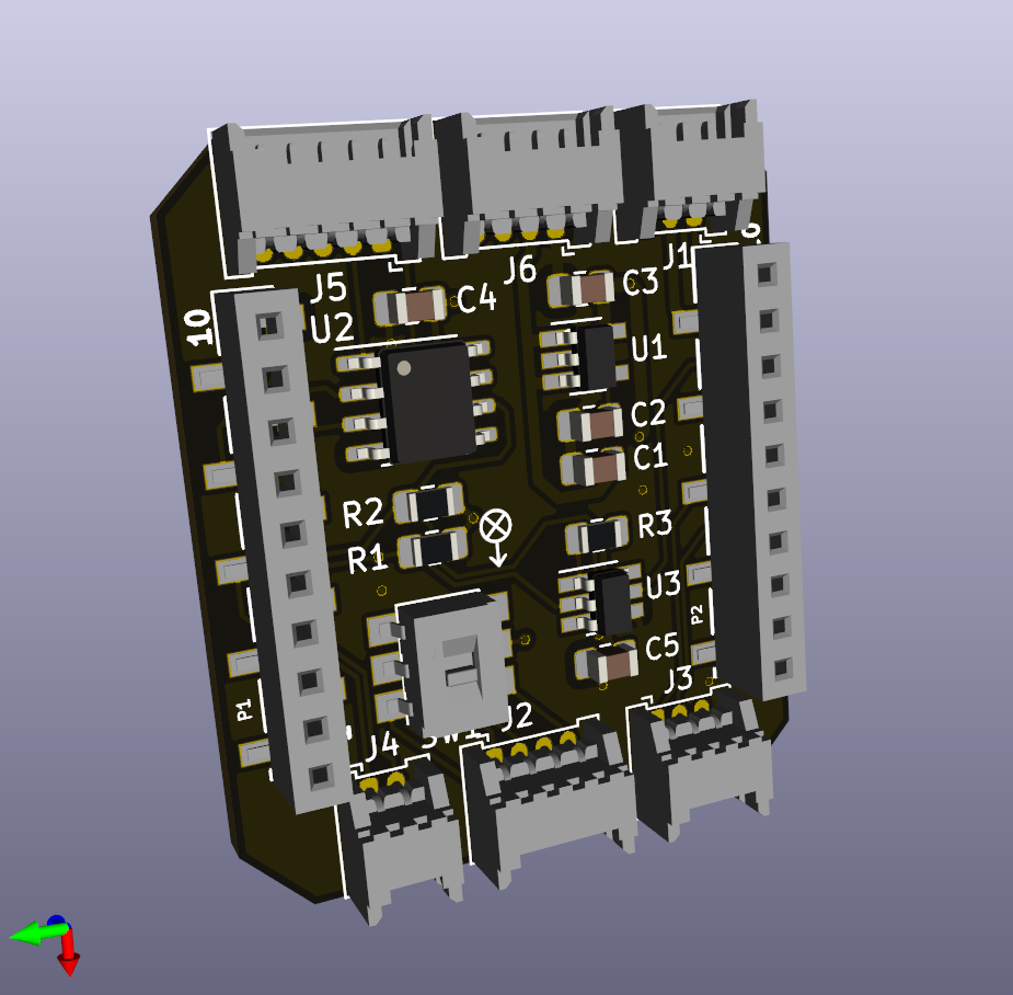
Schematic: here
Gerbers: here
License: CC BY 4.0.
Additionally, if you use this design for scientific work, please add a footnote or reference to this webpage:
Tom van Dijk (2020). Crazyflie 2 deck carrier. Micro Air Vehicle Lab (MAVLab), TU Delft. Retrieved from https://github.com/tomvand/cf-deck-carrier
This carrier board lets the Crazyflie 2 decks by Bitcraze AB be carried by other drones. The board functions similarly to a breakout board but with additional functions. The board is originally designed for the Eachine Trashcan, but may also be useful for other drones.
Nearly all of the features on this carrier board are optional, unused components can be left out to save weight and assembly time. Refer to the optional features section below to check which components should be installed for your application.
The carrier board should be connected to an autopilot using the connectors J1 to J5. The connectors are grouped by function. In nearly all cases the board can be connected directly to the corresponding autopilot pins.
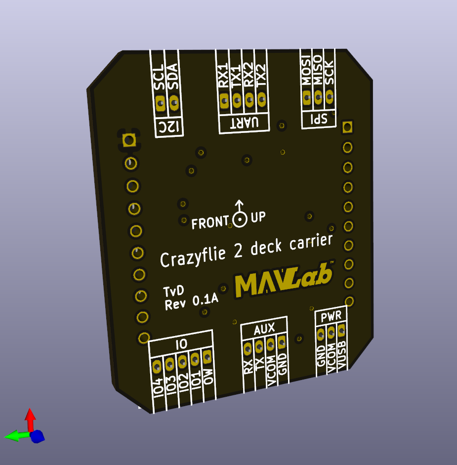
PWR (J1):
UART (J2):
SPI (J3):
J5 are typically used as Chip Select.I2C (J4):
IO (J5):
AUX (J6):
| Ref | Qnty | Value | Cmp name | Footprint | Approx. total cost / 5 |
|---|---|---|---|---|---|
| PCB, | 1 | € 4.57 | |||
| ------------------------ | |||||
| Subtotal | € 4.57 | ||||
| ------------------------ | |||||
| C1, | 1 | 1uF | C | 0805 | € 0.20 |
| C2, | 1 | 10nF | C | 0805 | € 0.20 |
| C3, | 1 | 4.7uF | C | 0805 | € 0.20 |
| C4, C5, | 2 | 0.1uF | C | 0805 | € 0.40 |
| R1, R2, R3, | 3 | 2.2k | R | 0805 | € 1.20 |
| ------------------------ | |||||
| Subtotal | € 2.20 | ||||
| ------------------------ | |||||
| U1, | 1 | LP2985-3.0 | LP2985-3.0 | SOT-23-5 | € 3.70 |
| U2, | 1 | PCA9536D | PCA9536D | SOIC-8 | € 7.15 |
| U3, | 1 | DS2484 | DS2484 | SOT-23-6 | € 3.35 |
| ------------------------ | |||||
| Subtotal | € 14.20 | ||||
| ------------------------ | |||||
| J1, | 1 | PWR | Molex PicoBlade 1x3 Horizontal Through-hole 53048-0310 | € 1.55 | |
| J2, | 1 | UART | Molex PicoBlade 1x4 Horizontal Through-hole 53048-0410 | € 1.85 | |
| J3, | 1 | SPI | Molex PicoBlade 1x3 Horizontal Through-hole 53048-0310 | € 1.55 | |
| J4, | 1 | I2C | Molex PicoBlade 1x2 Horizontal Through-hole 53048-0210 | € 1.25 | |
| J5, | 1 | IO | Molex PicoBlade 1x5 Horizontal Through-hole 53048-0510 | € 1.90 | |
| J6, | 1 | UART_AUX | Molex PicoBlade 1x4 Horizontal Through-hole 53048-0410 | € 1.85 | |
| P1, | 1 | CF_EXP_LEFT | BF090-10-X-B2 | € 6.60 | |
| P2, | 1 | CF_EXP_RIGHT | BF090-10-X-B2 | € 6.60 | |
| SW1, | 1 | CAS-220 | CAS-220B1 | € 9.20 | |
| ------------------------ | |||||
| Subtotal | € 32.35 | ||||
| ------------------------ | |||||
| Total | € 53.32 / 5 |
Find the gerber files here.
PCB manufactoring cost: ~€4.57 / 5 (excl. shipping cost, at JLCPCB, estimated by pcbshopper on Wednesday May 20th 2020)
SMT assembly files for JLCPCB: here.
C, R)| Cost / 5 | |
|---|---|
| Assembly incl. component cost | € 15.19 |
| Remaining components | € 46.55 |
| ---------- | |
| Total | € 61.74 |
C, R, U)| Cost / 5 | |
|---|---|
| Assembly incl. component cost | € 29.87 |
| Remaining components | € 32.35 |
| ---------- | |
| Total | € 62.22 |
(excl. shipping cost, assembly at JLCPCB; Wednesday May 20th 2020)
Recommended soldering order:
Components: J1 to J6
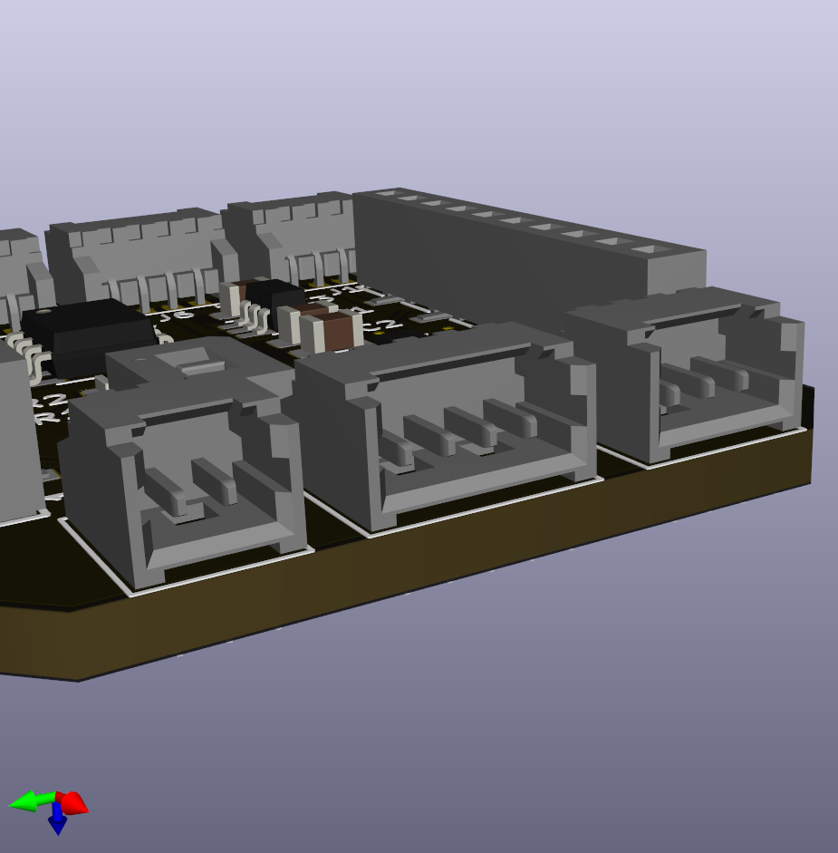
The PCB is designed for through-hole Molex Picoblade connectors. Unused connectors can be left out to save weight. Wires can also be soldered directly to the connector pads for permanent connections.
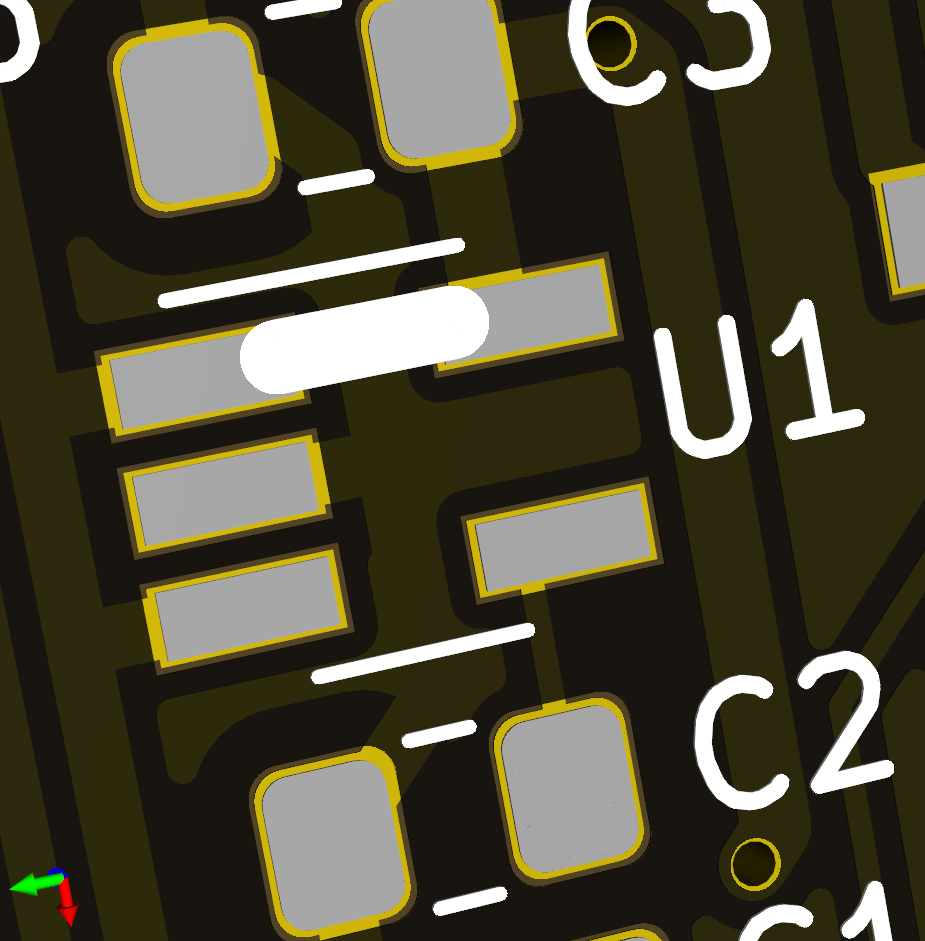
Components: U1, C1, C2, C3
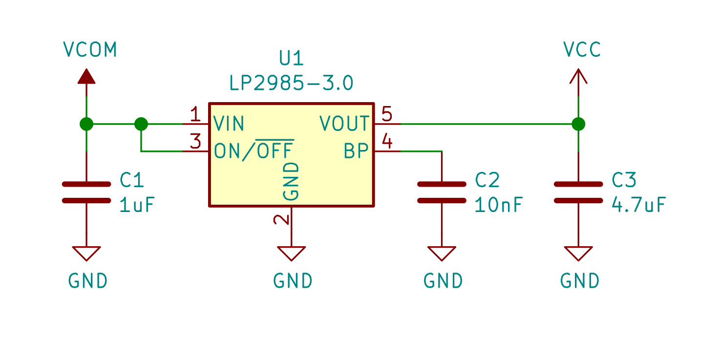
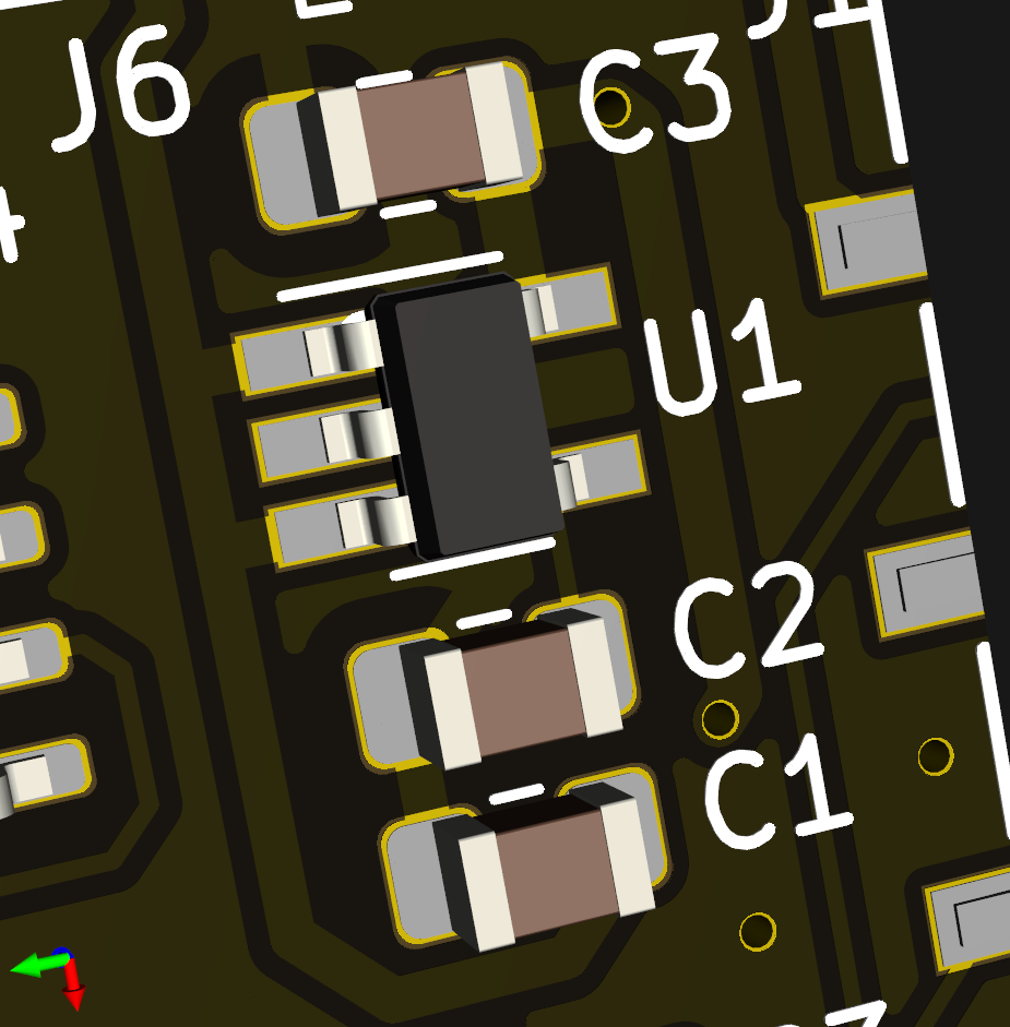
The carrier board includes a voltage regulator that supplies 3.0V at max 150mA. Input voltage VCOM can be ≤16V, although compatibility with the crazyflie decks should be checked!
For autopilots that already supply regulated 3.0V on VCOM, the voltage regulator can be replaced by a solder bridge between VCOM (pad 1) and VCC (pad 5) of U1 (marked by white line).
Components: R1, R2
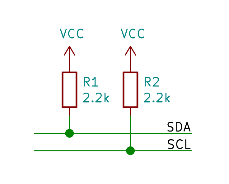
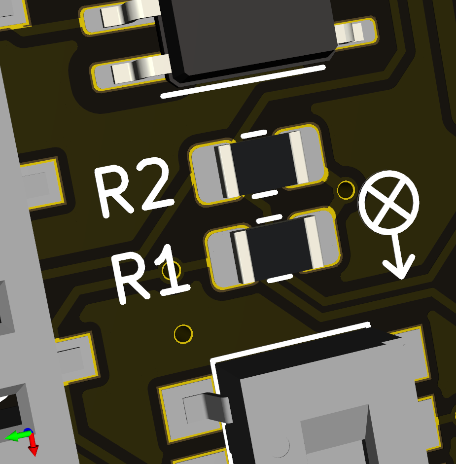
The board has space for I2C pull-up resistors (0805) (R1, R2) if these are not present on the autopilot.
Components: U2, C4
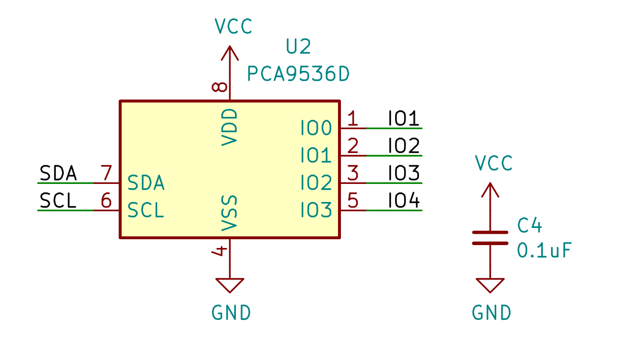
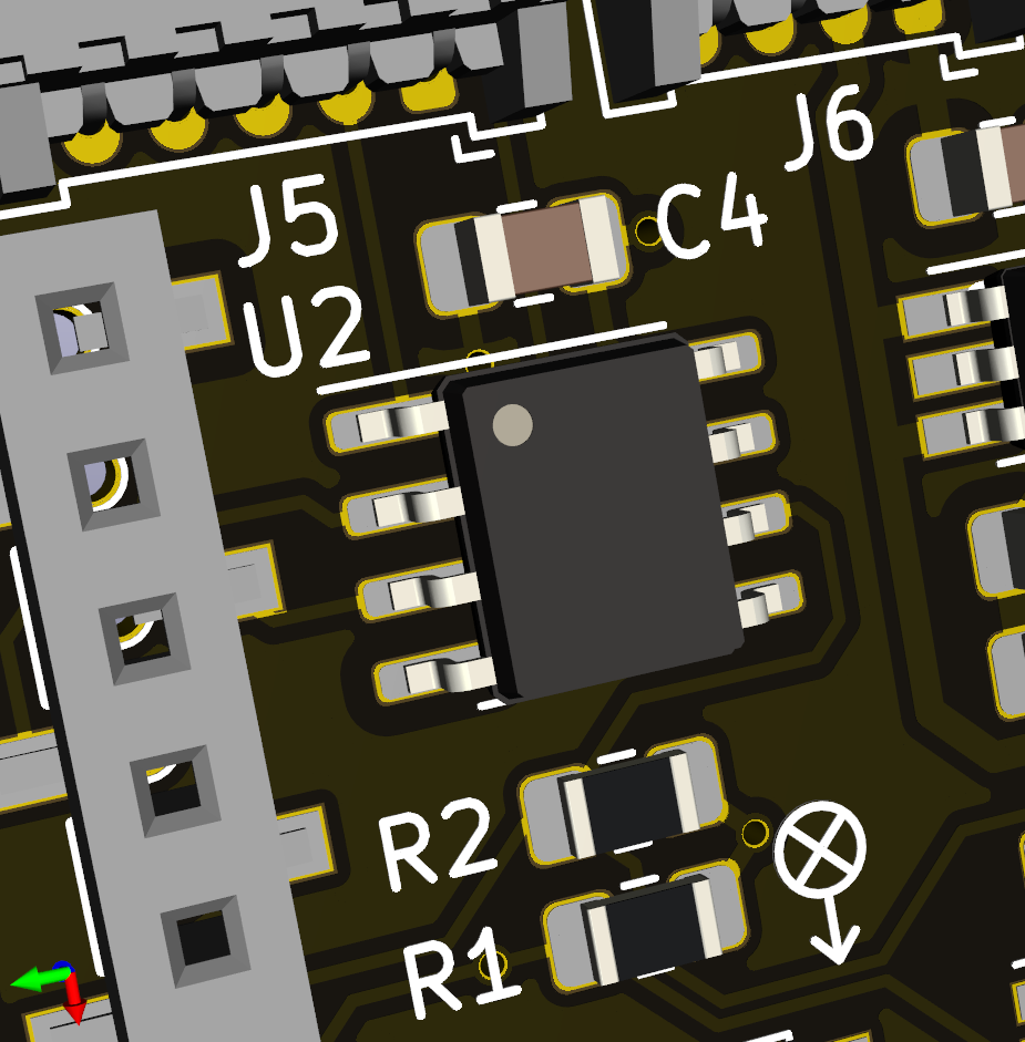
For drones with a limited number of free pins, the I2C-to-GPIO bridge U2 can be installed to drive the decks' IO pins. Since most of the IO pins serve as Chip Select for SPI communication, software drivers should take care that the I2C/GPIO operation is completed before SPI communication begins.
The IO inputs on the IO connector should not be used if the I2C-to-GPIO bridge is in use.
Components: U3, R3, C5
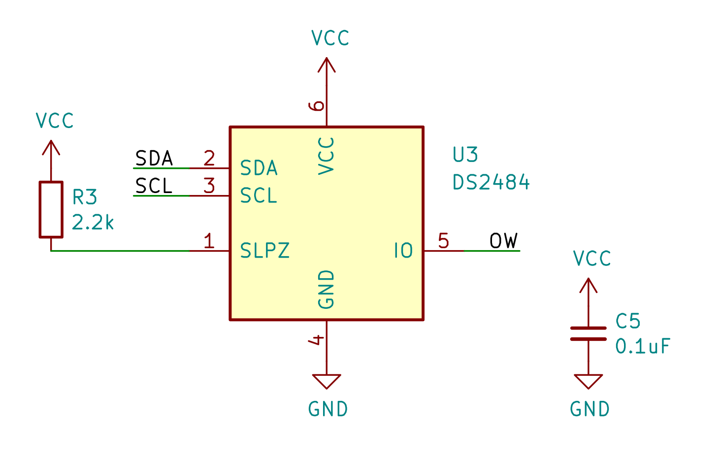
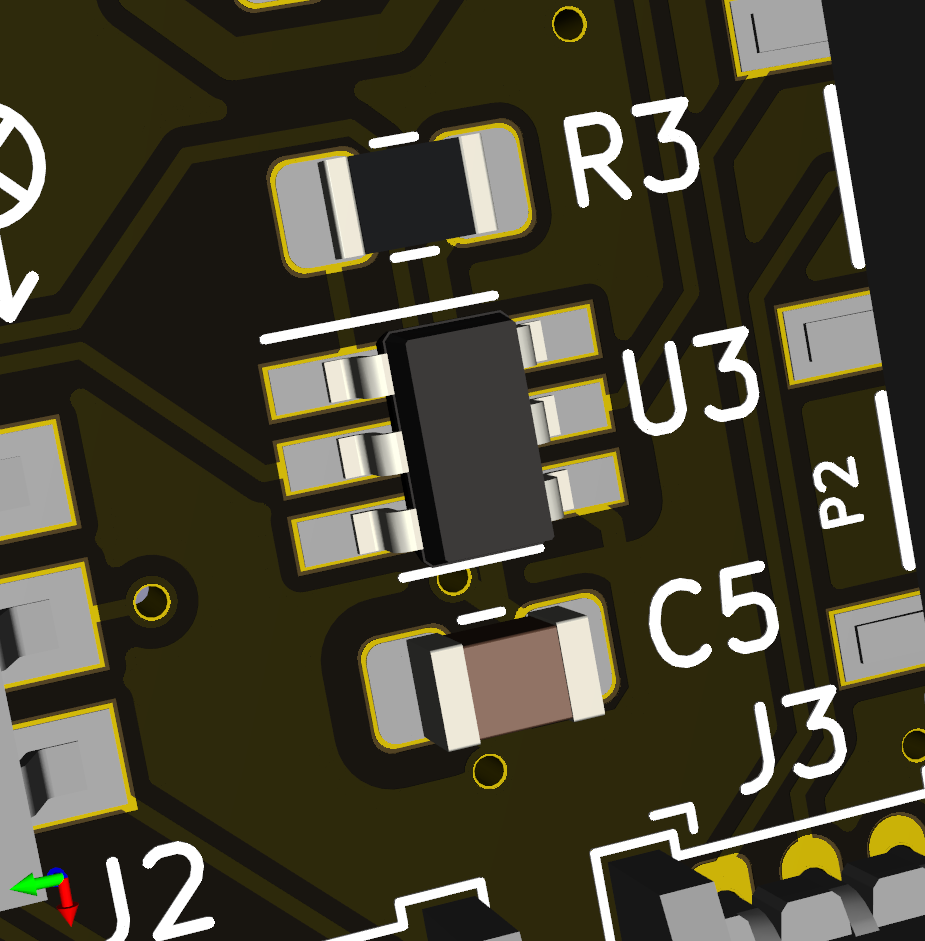
For drones with a limited number of free pins, the I2C-to-1-Wire bridge U3 can save another pin by routing 1-Wire data over the existing I2C lines. Note that most decks only use 1-Wire for identification and that not all autopilots support this feature. (Paparazzi, for instance, does not.)
The OW input on the IO connector should not be used if the I2C-to-1-Wire bridge is installed.
Components: J6, SW1
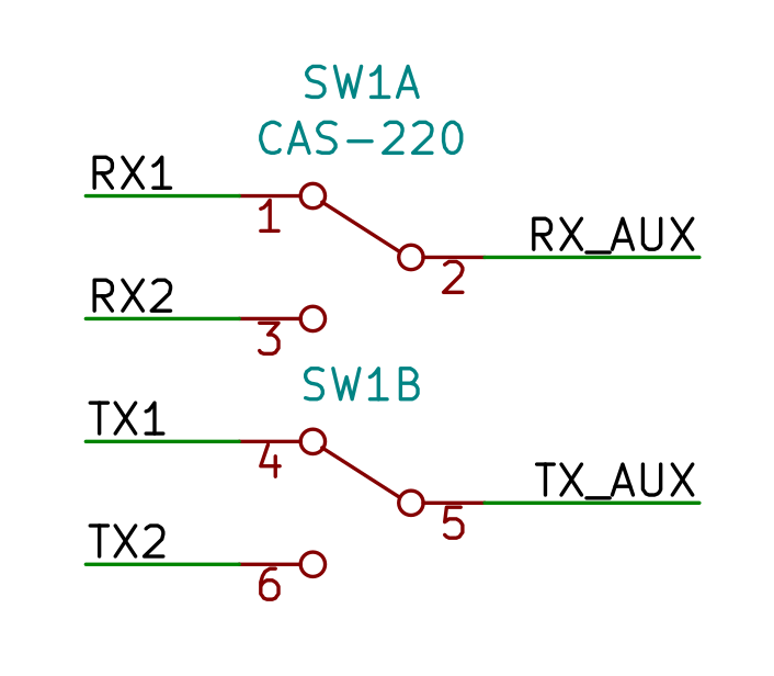
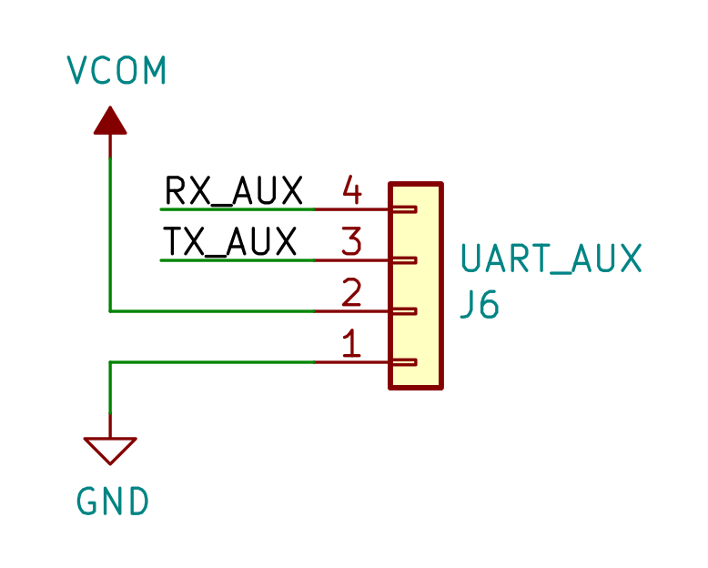
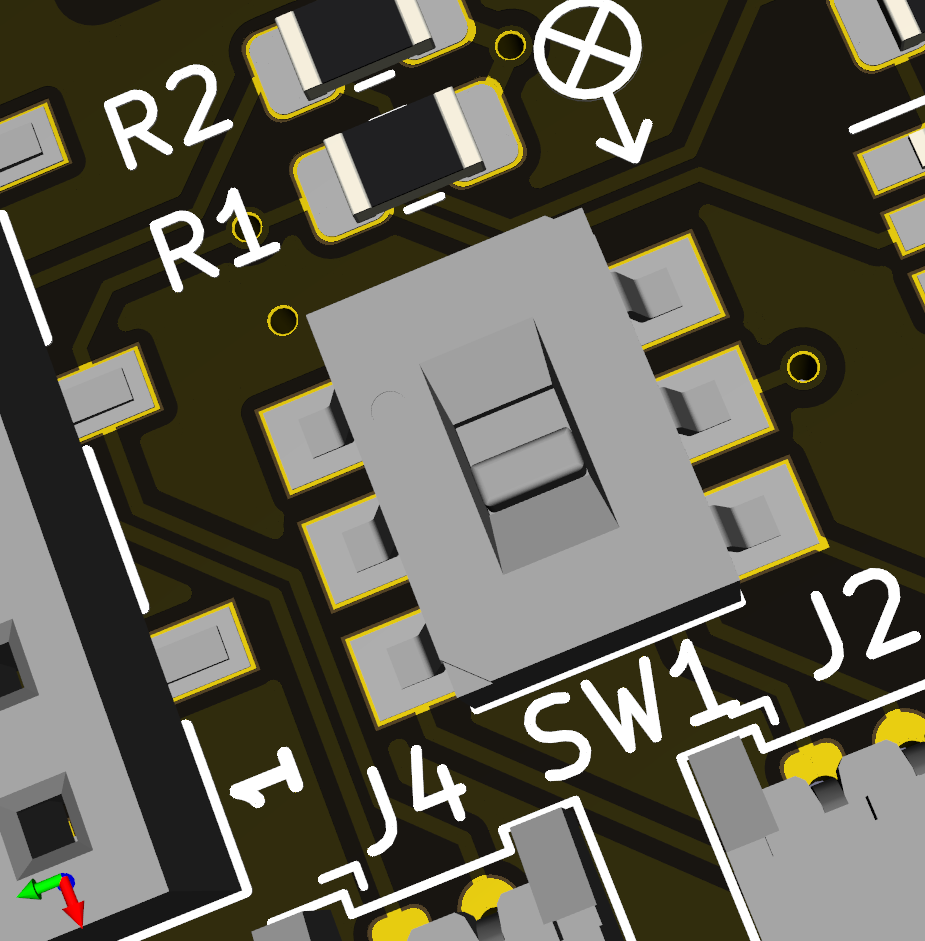
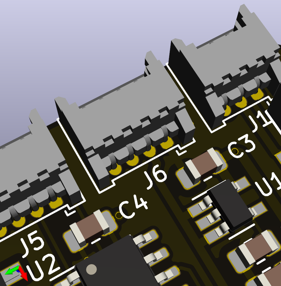
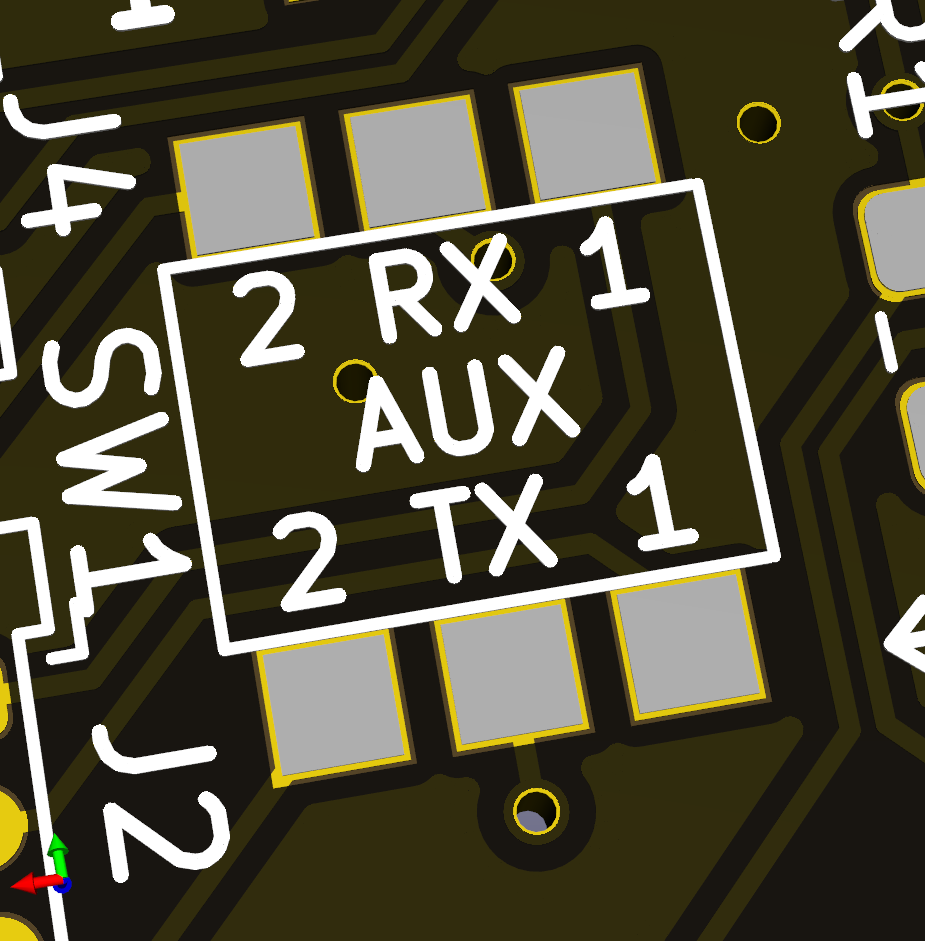
The AUX connector J6 can be used to connect another board to the carrier deck. The AUX connector provides unregulated power (VCOM) and a UART bus. Using switch SW1, the auxiliary UART can be connected to UART1 or UART2, depending on the decks that are in use.
For permanent installations, switch SW1 can be replaced by solder bridges between the relevant pads.
| Qty | Value | Footprint | References |
|---|---|---|---|
| 3 | 2.2k | Resistor_SMD:R_0805_2012Metric_Pad1.15x1.40mm_HandSolder | R1, R2, R3 |
| 2 | 0.1uF | Capacitor_SMD:C_0805_2012Metric_Pad1.15x1.40mm_HandSolder | C4, C5 |
| 1 | 10nF | Capacitor_SMD:C_0805_2012Metric_Pad1.15x1.40mm_HandSolder | C2 |
| 1 | 1uF | Capacitor_SMD:C_0805_2012Metric_Pad1.15x1.40mm_HandSolder | C1 |
| 1 | 4.7uF | Capacitor_SMD:C_0805_2012Metric_Pad1.15x1.40mm_HandSolder | C3 |
| 1 | CAS-220 | project-footprints:CAS-220B-wide-pads | SW1 |
| 1 | CF_EXP_LEFT | project-footprints:CF2-DECK-SMD-HOLES | P1 |
| 1 | CF_EXP_RIGHT | project-footprints:CF2-DECK-SMD-HOLES | P2 |
| 1 | DS2484 | Package_TO_SOT_SMD:SOT-23-6_Handsoldering | U3 |
| 1 | I2C | project-footprints:Molex_PicoBlade_53048-0210_1x02_P1.25mm_Horizontal_3D | J4 |
| 1 | IO | project-footprints:Molex_PicoBlade_53048-0510_1x05_P1.25mm_Horizontal_3D | J5 |
| 1 | LOGO | project-footprints:mavlab-logo-1-2mm | G*** |
| 1 | LP2985-3.0 | Package_TO_SOT_SMD:SOT-23-5_HandSoldering | U1 |
| 1 | PCA9536D | Package_SO:SOIC-8_3.9x4.9mm_P1.27mm | U2 |
| 1 | PWR | project-footprints:Molex_PicoBlade_53048-0310_1x03_P1.25mm_Horizontal_3D | J1 |
| 1 | SPI | project-footprints:Molex_PicoBlade_53048-0310_1x03_P1.25mm_Horizontal_3D | J3 |
| 1 | UART | project-footprints:Molex_PicoBlade_53048-0410_1x04_P1.25mm_Horizontal_3D | J2 |
| 1 | UART_AUX | project-footprints:Molex_PicoBlade_53048-0410_1x04_P1.25mm_Horizontal_3D | J6 |
| 1 | VAL** | bitcraze:EXP_ORIENTATION | EXP_ORIENTATION |


EbenezerBoadiBoateng/Arduino-Mega-260-R3-Ebenezer-Boadi-01230884b-
Recreating an Arduino mega on a kicad


the78mole/km271-wifi
A piece of hardware to be installed in a Buderus Logamatic 2107 to provide control and status over WiFi

j3270/1-Wire-Wing-pcb
Feather Wing PCB supporting 1-Wire via a DS2484 I2C to 1-Wire master, or selectable jumper for micros that support 1-Wire natively and bit-banging.


BeeEyeIoT/sensor-station-board
Complete KiCAD project for a sensor data collection station
It measures 33 × 28 mm and has 4 copper layers, 1.6 mm thick.
22 parts, built around the DS2484R+T, LP2985-30DBV, PCA9536D and CAS-220A. The full list of its parts is on this page, with links to each part's symbol and footprint where PCBKit's library has them.
From the tomvand/cf-deck-carrier repository on GitHub, at the commit this page was made from: the board is src/cf-deck-carrier/cf-deck-carrier.kicad_pcb. PCBKit opens the board in the browser, with nothing to install.
Its repository publishes it under the CC-BY-4.0 licence: you may reuse it on that licence's terms (keep the author's notice, and for a copyleft licence share your changes alike).