2 layers33 × 26.4 mm

 tomtor/ESPTiny4
KiCad ATtiny84/x14/x02 (SMD) and ESP-01 (ESP 8266) PCB boards
ESPTiny1614 is an open-source printed circuit board by tomtor, from the tomtor/ESPTiny repository on GitHub, published under the GPL-3.0 licence. It is a 2-layer board of 33 × 23.9 mm with 24 parts on 21 nets, routed with 190 tracks and 13 vias.
It is built around the ATTINY1614-SSN and BAT85. Its parts include 5 resistors, 4 capacitors, 3 ICs, 3 connectors and 2 diodes. It belongs with the ESP32, ESP8266 and AVR (ATmega, ATtiny) boards of this library.


The main function of the ATtiny is acting as a battery friendly low power co-processor for the ESP. A bit like the ULP low power co-processor of the ESP32, except with a lot more IO functions and program memory.
ATtiny and ESP combined use 22uA in sleep mode or even less when the ESP is switched off by the ATtiny with CS.
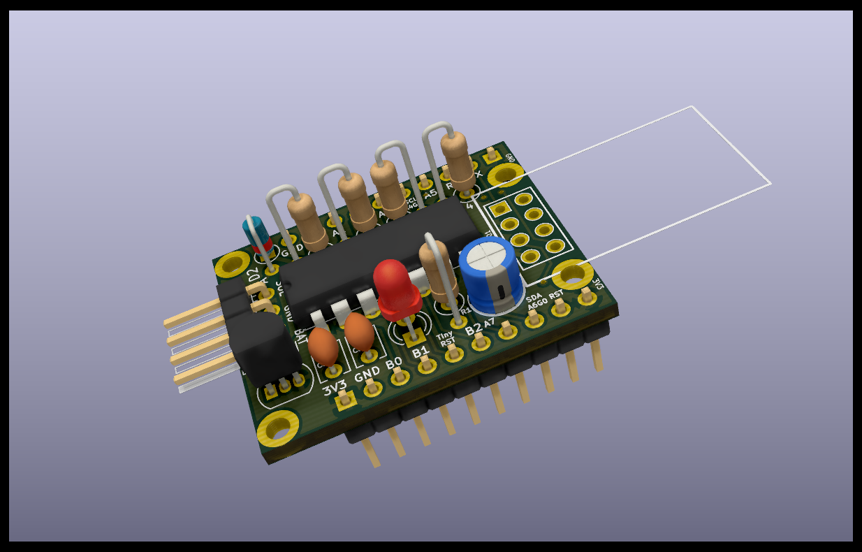
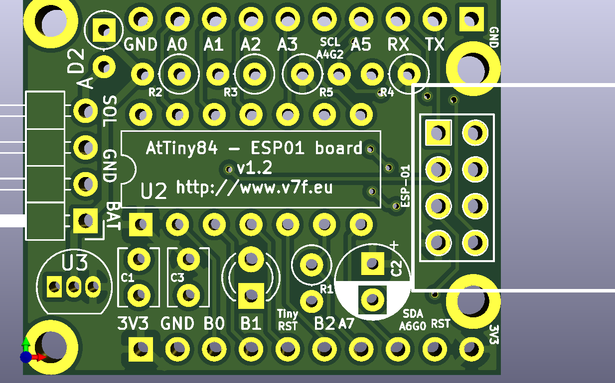
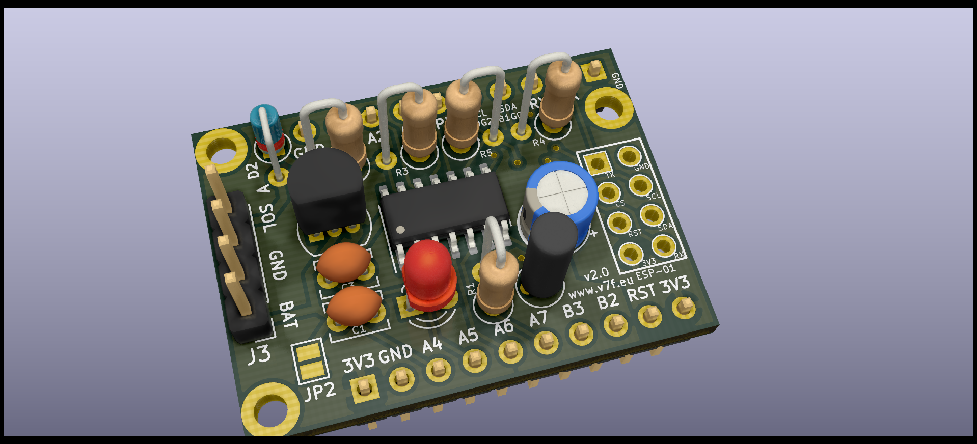
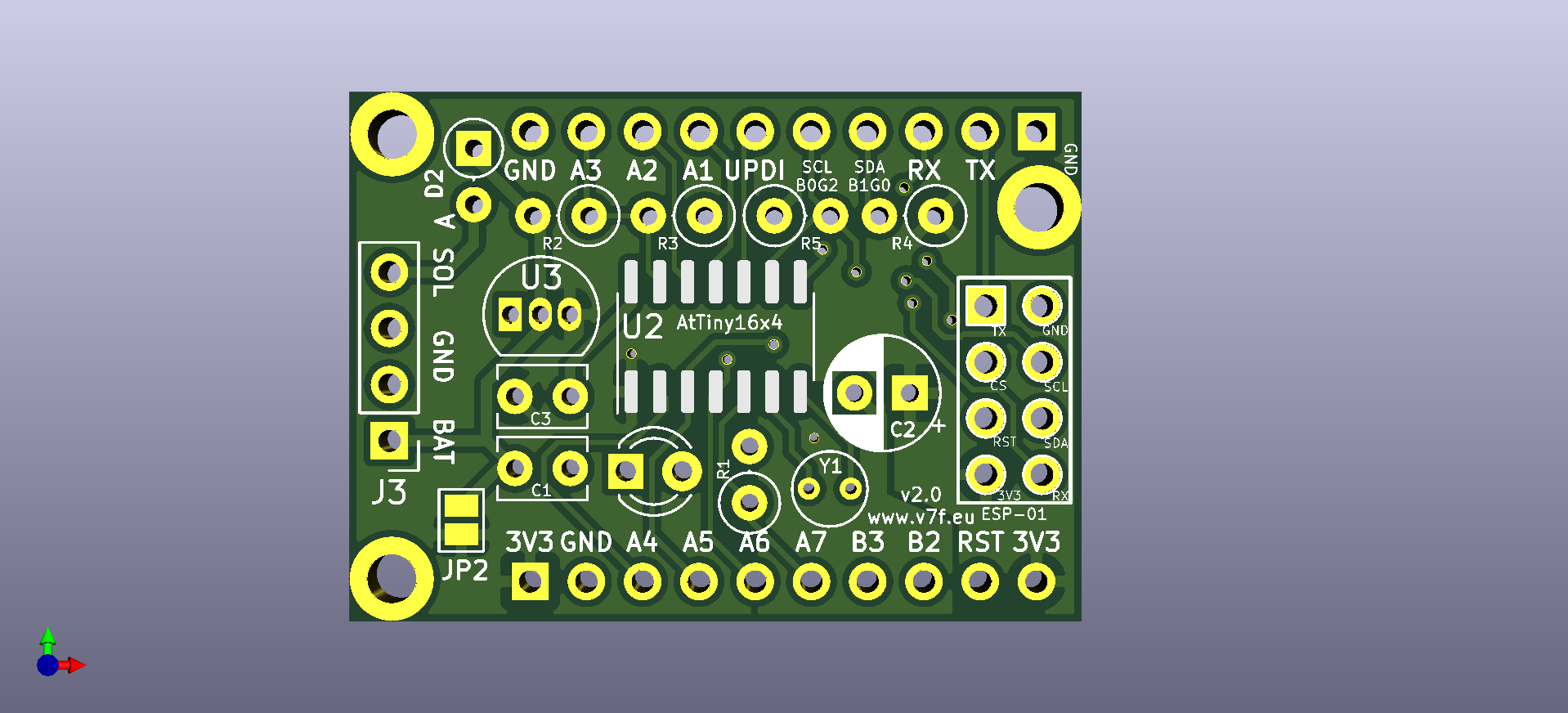
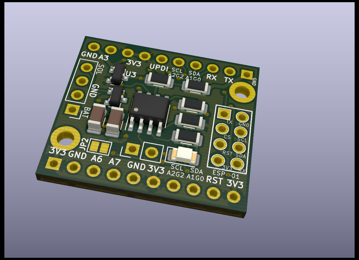
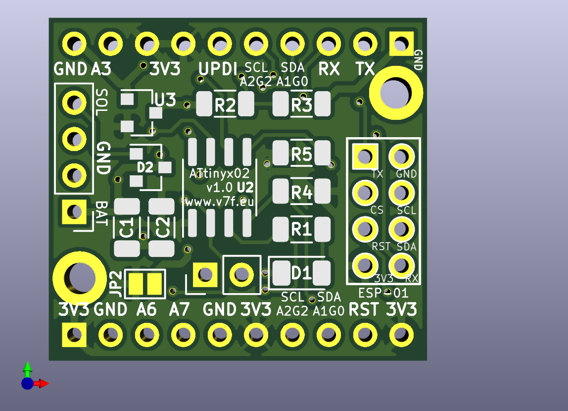
Usable on breadboard (ATtiny84: 9 rows high, leaves 2 rows empty and ATtiny16x4: 8 rows high) OR stand alone.
3 PCB designs: ATtiny84 or ATtiny16x4 or ATtinyx02
All components / features are optional:
The ATtiny wakes up the ESP every 10 minutes by pulling RST low and sends a counter and the supply voltage to it.
OTA for ESP program updates is activated for 20s when the I2C communication fails. This can be triggered by resetting the ESP by pulling the RST line low. Because the ATtiny is most of the time sleeping the I2C communication will fail.
There is a small chance that the ATtiny will reset the ESP during upload when the 10 minute interval is completed. You can prevent this by pulling the ATtiny RST low when using OTA, or just upload again.
https://github.com/tomtor/ESPTiny/raw/master/ESPTiny.pdf
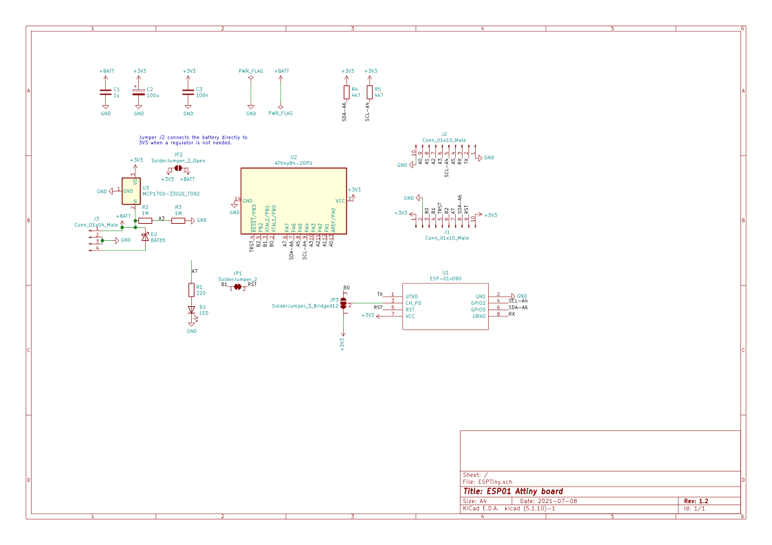
https://github.com/tomtor/ESPTiny/raw/master/ESPTiny1614.pdf
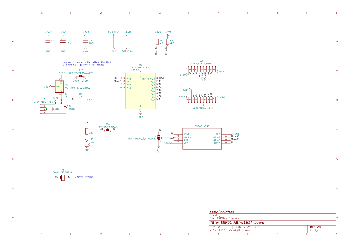
https://github.com/tomtor/ESPTiny/raw/master/ESPTiny402.pdf
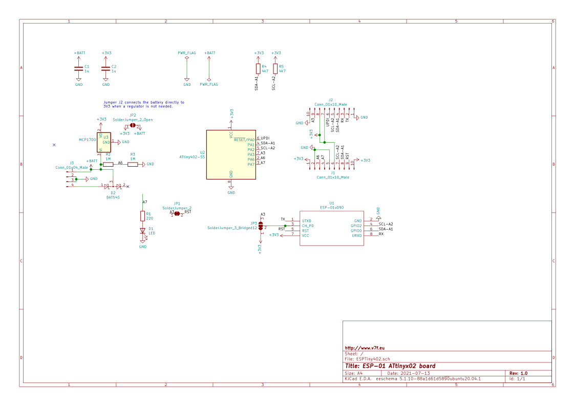
| Qty | Value | Footprint | References |
|---|---|---|---|
| 2 | 10p | Capacitor_THT:C_Disc_D3.0mm_W1.6mm_P2.50mm | C4, C5 |
| 2 | 1M | Resistor_THT:R_Axial_DIN0207_L6.3mm_D2.5mm_P2.54mm_Vertical | R2, R3 |
| 2 | 4k7 | Resistor_THT:R_Axial_DIN0207_L6.3mm_D2.5mm_P2.54mm_Vertical | R4, R5 |
| 2 | Conn_01x10_Male | Connector_PinHeader_2.54mm:PinHeader_1x10_P2.54mm_Vertical | J1, J2 |
| 1 | 100n | Capacitor_THT:C_Disc_D3.8mm_W2.6mm_P2.50mm | C3 |
| 1 | 1u | Capacitor_THT:C_Disc_D3.8mm_W2.6mm_P2.50mm | C1 |
| 1 | 220 | Resistor_THT:R_Axial_DIN0207_L6.3mm_D2.5mm_P2.54mm_Vertical | R1 |
| 1 | ATtiny1614-SS | Package_SO:SOIC-14_3.9x8.7mm_P1.27mm | U2 |
| 1 | BAT85 | Diode_THT:D_DO-35_SOD27_P2.54mm_Vertical_AnodeUp | D2 |
| 1 | Conn_01x04_Male | Connector_PinHeader_2.54mm:PinHeader_1x04_P2.54mm_Vertical | J3 |
| 1 | Crystal 32.768kHz | Crystal:Crystal_Round_D3.0mm_Vertical | Y1 |
| 1 | ESP-01v090 | ESP8266:ESP-01 | U1 |
| 1 | LED | LED_THT:LED_D3.0mm | D1 |
| 1 | MCP1700-3302E_TO92 | Package_TO_SOT_THT:TO-92_Inline | U3 |
| 1 | SolderJumper_2 | Jumper:SolderJumper-2_P1.3mm_Bridged_RoundedPad1.0x1.5mm | JP1 |
| 1 | SolderJumper_2_Open | Jumper:SolderJumper-2_P1.3mm_Open_Pad1.0x1.5mm | JP2 |
| 1 | SolderJumper_3_Bridged12 | Jumper:SolderJumper-3_P1.3mm_Bridged12_RoundedPad1.0x1.5mm_NumberLabels | JP3 |
The 21 most common of 24 parts.

tomtor/ESPTiny
KiCad ATtiny84/x14/x02 (SMD) and ESP-01 (ESP 8266) PCB boards

tomtor/ESPTiny
KiCad ATtiny84/x14/x02 (SMD) and ESP-01 (ESP 8266) PCB boards

MycroftAI/hardware-mycroft-mark-II
Mycroft's Mark II Rpi mechanical, electrical and industrial designs

MarkR42/malenki-esc
A small electronic speed controller for e.g. tiny fighting robots or other rc models


vladbelous/avr-attiny1614-mini
AVR attiny1614 (tinyAVR 1-series) mini board


ff0000wire/diyBMS_CurrentVoltage_ADS1115
Isolated current and voltage sensor for up to 850V based on ADS1115 and attiny1614
It measures 33 × 23.9 mm and has 2 copper layers, 1.6 mm thick.
24 parts, built around the ATTINY1614-SSN and BAT85. The full list of its parts is on this page, with links to each part's symbol and footprint where PCBKit's library has them.
From the tomtor/ESPTiny repository on GitHub, at the commit this page was made from: the board is ESPTiny1614.kicad_pcb and its schematic ESPTiny.kicad_sch. PCBKit opens the board in the browser, with nothing to install.
Its repository publishes it under the GPL-3.0 licence: you may reuse it on that licence's terms (keep the author's notice, and for a copyleft licence share your changes alike).