4 layers220.5 × 51 mm
MuonScope
manvalan/MuonScope
Piano di rivelazione MuonScope con 16 fotodiodi VBPW34S in matrice 4×4 a passo 10 mm, per il bus MIKILAB REV5.1.
102 parts

 tjhowse/sand_drawing24
Code, PCBs and CAD for a SCARA-based sand drawing robot
Sand drawing is an open-source printed circuit board by tjhowse, from the tjhowse/sand_drawing repository on GitHub. It is a 2-layer board of 54.2 × 81.5 mm with 41 parts on 47 nets, routed with 229 tracks and 15 vias.
It is built around the ESP32-WROOM-32D, AP63203WU and CGA3E2X7R1H104K080AA, with the CRGP0603F10K, CGA5L1X7R1V106K160AE and CL21C101JBANNNC among its other parts. Its parts include 17 diodes, 6 capacitors, 6 connectors, 2 ICs and 2 switches. It belongs with the ESP32 boards of this library.


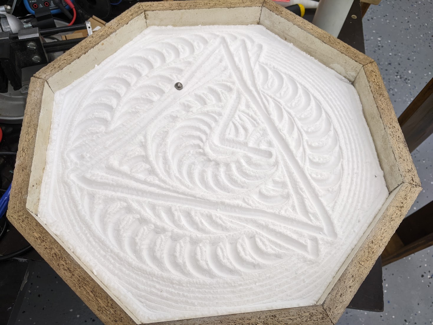
So you've been reading about all the benefits of this "mindfulness" thing and you want to give it a try. You do some research and learn it requires "meditation", "introspection" and other kinds of tedious woo. Who has time for that? It's {current_year} for christ's sake! I don't want a tiny tray of rocks and sand on my desk to rake around. Surely there's some turn-key solution to this problem already.
That's what this project is for. Outsource responsibility for an ordered mind to make more time for the important things, like computer games. And croissants.
This project (will contain/contains) all the knowledge you will need to build your own sand drawing robot. Heavily inspired by the likes of Sandsara and Sisyphus. It's a robot that moves a ball around in a bed of sand to draw cool patterns. The patterns can be updated via wifi, and it can cycle through them, you can create your own, etc, etc. This project is open source, cheap, and hopefully as easy as possible to build.
This isn't a Lego set. You'll need to have access to the following skills:
I'll do my best to make the instructions as comprehensive and comphrehensible as I can. I appreciate any and all feedback.
Playlist on Youtube. Maybe worth watching.
The PCB is quite simple and cheap. PCBWay generously sponsored a production run of the v1.2 PCBs and they came out perfect. You can order the PCB using this link and I'll get a small cut. PCBWay asked me to review the board in a youtube video and link it in the readme, but required no further quid pro quo.
For now the build logs are on my wiki. Over time they'll morph into actual instructions and end up in this repo.
None of these parts are particularly hard to find. Check ebay and whatnot. Try to buy local if you can. It's hard to guess how much it will all cost in total, but I've tried to design everything to be as economical as possible. Excluding the housing I would (very roughly) estimate the BoM to come out to around AUD$200. The housing could be as cheap as AUD$50 (Melamine board, polycarbonate) or as expensive as you want, with lacquered hardwood and tempered glass.
These bills of material are slightly out of date. Consult the youtube videos.| Item | Type | Count | Note |
|---|---|---|---|
| Laser cut parts | Various | Many | The current best solution is made from 3mm laser cut plywood. A 3D printed variant is quite possible. |
| Stepper pulley | GT2-20, 12.35mm high | 2 | My steppers had pulleys from the factory. |
| Belt | S2M belt 120mm | 2 | S2M ≈ GT2. |
| Belt | S2M belt 278mm | 1 | |
| Shaft 1 | 8mm x 90mm | 1 | Mild steel is easier to cross-drill than stainless. |
| Shaft 2 | 8mm x 33mm | 1 | |
| Bearing | 608 | 6 | Cheap skate bearings are fine. |
| Washers | 8mm ID, 15.7mm OD | 5 | OD not critical, but it must not rub on outer race of bearings. |
| Washers | 3mm ID, 6.8mm OD | 12 | |
| Bolts | M3x12mm | 8 | I used all 20mm and cut them to length. |
| Bolts | M3x20mm | 2 | |
| Nylock nuts | M3 | 2 | Nylock not critical. |
| Pins | 2mm diameter | 5 | Roll pins would be best, I used nails. +1 extra for pinning shaft 1 into the bearings. |
| Magnets | 12mm diameter, 2mm high neodymium | 2-4 | Situational dimensions. Get a variety of sizes to aid experimentation. |
| Cable ties | 200mm x 4.6mm Nylon | 2 | Dimensions not critical. |
| Item | Type | Count | Note |
|---|---|---|---|
| Microcontroller | ESP-WROOM-32D | 1 | Wifi and bluetooth built-in |
| Stepper motor | NEMA-17 | 2 | 200 steps/revolution, around 40mm long, at least 30 N.cm of holding torque. It's not critical, really. |
| Stepper driver | Pololu pinout | 2 | A4988, DRV8825 or TMC2100 in increasing order of preference |
| PCB | Custom made | 1 | The design is here. It's easier and cheaper to have one made than you might imagine. |
| Hall effect sensors | SS49E | 2 | Used for detecting arm position. |
| PSU | 12v DC 1A | 1 | A wall wart should be fine. |
| Stepper driver socket | 16x1 2.54mm female | 2 | https://au.rs-online.com/web/p/pcb-sockets/2304893/ |
| Stepper motor socket | 4x1 3.5mm | 2 | https://au.rs-online.com/web/p/pcb-headers/8971039/ |
| Stepper motor plug | 4x1 3.5mm | 2 | https://au.rs-online.com/web/p/pcb-terminal-blocks/8971004/ |
| Optoswitch socket | 3x1 3.5mm | 2 | https://au.rs-online.com/web/p/pcb-headers/8971020/ |
| Optoswitch plug | 3x1 3.5mm | 2 | https://au.rs-online.com/web/p/pcb-terminal-blocks/8971001/ |
| Power socket | 2x1 3.5mm | 1 | https://au.rs-online.com/web/p/pcb-headers/8971026/ |
| Power plug | 2x1 3.5mm | 1 | https://au.rs-online.com/web/p/pcb-terminal-blocks/8970998/ |
| Buttons | 6mm | 2 | https://au.rs-online.com/web/p/tactile-switches/1359534/ |
| UART Header | 3x1 2.54mm male | 1 | https://au.rs-online.com/web/p/pcb-headers/8967364/ |
| 12VDC Barrel socket | 2.1mm pin | 1 | https://au.rs-online.com/web/p/dc-power-sockets/0448370/ |
| Item | Type | Count | Note |
|---|---|---|---|
| Base | Wooood? | 1 | Holds the steppers and circuitry. |
| Top | Wooood? | 1 | Any convex polygon should work. |
| Bed | Glass? | 1 | |
| Lid | Glass | 1 | |
| Sand | Sand | 31378908 | < 100 μm grains, dry. |
To flash the software onto the ESP32 you'll need to use the provided scripts flash32.sh and write32.sh. You'll have to update them with the current version of micropython and the device name of your serial port adapter. When flashing micropython you'll need to hold down the IO0 button while connecting power, then release it five or so seconds after powering on. You can then run flash32.sh and it'll write the "OS" onto the chip. Then you can repower again and run write32.sh to load the project's scripts onto the board.
The ESP-WROOM-32 has wifi and BLE built in. Currently the robot connects to a wifi network, then an MQTT server, to receive commands. Bluetooth should also be possible in the future.
There are a few topics that the robot listens to. Each topic starts with {secrets.mqtt_root}/sand_drawing/. I suggest you publish patterns/generators with the retain bit so the robot starts up and then begins that pattern.
| Topic | Example payload | Description |
|---|---|---|
pattern | G28 X,G28 Y,G1 X0 Y175,G1 X123 Y123,G1 X175 Y0,J0 2 | Starts drawing the pattern defined by the GCODE in the payload. |
generator | Here | Starts drawing the pattern defined by the generator in the payload. See below for details on generators. |
save_generator | 1.pat {generator string} | Saves the generator to a file in the robot's flash storage. The file extension must be .pat. A blank string will erase the generator. |
run_generator | 1.pat | Starts drawing the previously saved generators. |
delete_generator | 1.pat | Deletes a generator saved to the robot. |
list_generators | N/A | Publishes a list of filenames to generator_list topic. |
shuffle_generators | 3600 | Randomly picks a saved generator and starts drawing it. Optionally provide a number of seconds before choosing another random generator |
There are some files you'll need to edit before your robot will work for you, probably. #TODO populate this section.
There are currently two ways to design patterns for the robot.
This is a sequence of coordinates that define the path of the ball, as well as changing modes and looping. The following GCODES are currently supported. GCODES are separated by a comma.
| Name | GCODE | Example | Description |
|---|---|---|---|
| Home axis | G28 | G28 X,G28 Y, | Home either the X or Y axis. Any command that needs an absolute position reference will fail unless both axes have been homed first. |
| Move | G1 | G1 X10 Y50 S100, | Go to the X and Y coordinates specified at 100mm/s. Currently the speed field is ignored. The G1 movement mode carefully tracks every step and should be perfectly accurate if your steppers do not slip. |
| Fast move | G0 | G0 X10 Y50 S100, | Same as G1 however the step signal square wave is generated using PWM so some resolution is lost. At time of writing it is not well-supported. It's really fast though. |
| Coordinate mode | G16 | G16 0, | This setting is used to control the interpretation of the X and Y parameters in the G0 and G1 commands. 0: Raw speed, 1: Raw angle, 2: Cartesian (Default), 3: Polar (unimplemented) |
| Jump | J0 | J0 3, | This jumps to the specified line in the GCODE-defined pattern. Used for creating loops. |
| Absolute coordinate mode | G90 | G90 | Puts the robot into absolute movement mode. Coordinates in G0/G1 commands are interpreted as absolute position references. (Default) |
| Relative coordinate mode | G91 | G91 | Puts the robot into relative movement mode. Coordinates in G0/G1 commands are interpreted as movement vectors from the previous position. |
You can define a pattern using a python generator function. Examples here. This is probably the best option for non-trivial patterns.
Keep the target hardware in mind when writing generators. It's very resource-constrained. Try to limit RAM usage, and think hard before importing anything. There are some helper functions and constants in-scope that you can use.
| Qty | Value | Footprint | References |
|---|---|---|---|
| 17 | 100V 850mV@2A Schottky Diode | Diode_SMD:D_SMB | D1, D2, D3, D4, D5, D6, D7, D8, D10, D11, D12, D13, D14, D15, D16, D17 +1 |
| 4 | MountingHole | MountingHole:MountingHole_3.2mm_M3 | H1, H2, H3, H4 |
| 2 | 100nF/50V ±10% | Capacitor_SMD:C_0603_1608Metric | C3, C6 |
| 2 | 22µF/25V ±20% | Capacitor_SMD:C_1206_3216Metric | C4, C5 |
| 1 | 10k 1% 0.25W | Resistor_SMD:R_0603_1608Metric | R1 |
| 1 | 10µF/35V ±10% | Capacitor_SMD:C_1206_3216Metric | C2 |
| 1 | 12V GND | Connector_Phoenix_MC:PhoenixContact_MCV_1,5_2-G-3.5_1x02_P3.50mm_Vertical | J0 |
| 1 | 50V 100pF ±5% | Capacitor_SMD:C_0805_2012Metric | C1 |
| 1 | 6.8µH | sand_drawing_parts:WURTH_6060 | L1 |
| 1 | AP63203WU | sand_drawing_parts:TSOT-26-6 | U1 |
| 1 | Driver1 | Module:Pololu_Breakout-16_15.2x20.3mm | A1 |
| 1 | Driver2 | Module:Pololu_Breakout-16_15.2x20.3mm | A2 |
| 1 | EN | Button_Switch_THT:SW_PUSH_6mm | SW1 |
| 1 | ESP32-WROOM-32D | Custom:ESP32-WROOM-32 | U2 |
| 1 | IO0 | Button_Switch_THT:SW_PUSH_6mm | SW2 |
| 1 | Opto 1 | Connector_Phoenix_MC:PhoenixContact_MCV_1,5_3-G-3.5_1x03_P3.50mm_Vertical | J3 |
| 1 | Opto 2 | Connector_Phoenix_MC:PhoenixContact_MCV_1,5_3-G-3.5_1x03_P3.50mm_Vertical | J4 |
| 1 | Stepper1 | Connector_Phoenix_MC:PhoenixContact_MCV_1,5_4-G-3.5_1x04_P3.50mm_Vertical | J1 |
| 1 | Stepper2 | Connector_Phoenix_MC:PhoenixContact_MCV_1,5_4-G-3.5_1x04_P3.50mm_Vertical | J2 |
| 1 | UART | Connector_PinSocket_2.54mm:PinSocket_1x03_P2.54mm_Vertical | J5 |
manvalan/MuonScope
Piano di rivelazione MuonScope con 16 fotodiodi VBPW34S in matrice 4×4 a passo 10 mm, per il bus MIKILAB REV5.1.

adamjvr/fantoccia
An Open Source DAQ hardare system based on https://github.com/marionette-daq/marionette-hardware


JitterCompany/debug-tools
Collection of useful utility PCBs for development purposes

shivamtiwari020505/Automotive-BLE-CAN-Module
KiCad hardware design for an automotive BLE-to-CAN module


It measures 54.2 × 81.5 mm and has 2 copper layers, 1.6 mm thick.
41 parts, built around the ESP32-WROOM-32D, AP63203WU, CGA3E2X7R1H104K080AA and CRGP0603F10K. The full list of its parts is on this page, with links to each part's symbol and footprint where PCBKit's library has them.
From the tjhowse/sand_drawing repository on GitHub, at the commit this page was made from: the board is pcb/sand_drawing/sand_drawing.kicad_pcb and its schematic pcb/sand_drawing/sand_drawing.kicad_sch. PCBKit opens the board in the browser, with nothing to install.
Its repository states no licence, so its author keeps all rights: ask tjhowse before reusing the design.