2 layers41 × 40 mm
USBSwitch
JitterCompany/debug-tools
Collection of useful utility PCBs for development purposes
18 partsMIT
 JitterCompany/debug-tools
Collection of useful utility PCBs for development purposes
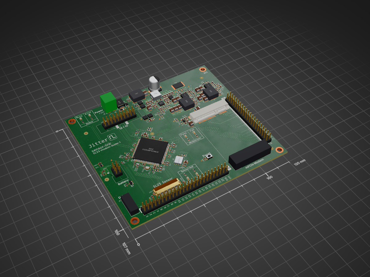
SL23-modem tester is an open-source printed circuit board by JitterCompany, from the JitterCompany/debug-tools repository on GitHub, published under the MIT licence. It is a 4-layer board of 120 × 107 mm with 229 parts on 235 nets, routed with 2,167 tracks and 708 vias.
It is built around the STM32L4R7ZIT6, MCP9701A-E/TO and W25Q256JVEIQ, with the BQ25672RQMR, SLG59M301V and CGA3E2X7R1H104K080AA among its other parts. Its parts include 97 capacitors, 57 resistors, 10 diodes, 9 connectors and 7 ICs. It belongs with the STM32 boards of this library.


KiCad projects for the small debug, programming and test boards used across Jitter
projects. Each board has its own folder; manufacturing files are in production/.
Most Jitter boards expose a single 6-pin Würth REDFIT IDC SKEDD footprint that carries both SWD and a UART. SKEDD connectors press straight into plated holes, so the target board needs no mating connector. The adapters below convert a debug probe's native header to that 6-pin cable.
| Board | Probe side | Notes |
|---|---|---|
| BMP-REDFit-adapter | Black Magic Probe: standard 10-pin 1.27 mm Arm Cortex Debug header + 4-pin PicoBlade UART | the 10-pin is the common Arm/MIPI-10 JTAG/SWD pinout, so most Cortex probes fit (UART via the separate PicoBlade) |
| HSprobe-REDFit-adapter | hs-probe: 14-pin 1.27 mm STDC14 | STDC14 is ST's STLINK-V3 connector (Arm 10-pin on pins 3–12, UART on 13/14), so STLINK-V3 should fit too |
| JLink-REDFit-adapter | J-Link: standard 20-pin 2.54 mm Arm JTAG header + 4-pin PicoBlade UART | other 20-pin tools give SWD; UART on pins 5/17 is J-Link VCOM specific (else use the PicoBlade) |
| Board | Purpose |
|---|---|
| JLink-to-TC2030-IDC__microchip | J-Link 20-pin to a Tag-Connect TC2030-IDC with Microchip's pinout |
| jtag-swd | 10-pin Cortex SWD header broken out to 2.54 mm pin headers |
| Board | Purpose |
|---|---|
| USBSwitch | USB-A / micro-USB passthrough with jumpers to disconnect the data lines and select VBUS from the host or an external 5 V banana-jack supply |
| Board | Purpose |
|---|---|
| SL23-modem-tester | Test jig for Sensor Link plug-in modules (mini-PCIe LTE modem, SL23 sensor extension) |
libraries/KicadComponents and tools/pcb_release are git submodules
(git submodule update --init). Boards are checked and released by the shared KiCad CI
in .github/workflows.
| Qty | Value | Footprint | References |
|---|---|---|---|
| 34 | 0.1u | Capacitor_SMD:C_0603_1608Metric | C12, C13, C14, C15, C20, C32, C35, C38, C47, C50, C53, C57, C59, C63, C100, C107 +18 |
| 18 | 10u | Capacitor_SMD:C_0805_2012Metric | C8, C10, C11, C19, C21, C22, C23, C24, C25, C26, C65, C67, C70, C75, C82, C105 +2 |
| 17 | 10k | Resistor_SMD:R_0603_1608Metric | R2, R15, R16, R20, R26, R27, R29, R31, R32, R39, R42, R45, R48, R49, R53, R57 +1 |
| 17 | TestPoint | TestPoint:TestPoint_THTPad_D1.0mm_Drill0.5mm | TP1, TP2, TP3, TP6, TP7, TP8, TP10, TP11, TP12, TP13, TP16, TP17, TP34, TP35, TP38, TP43 +1 |
| 6 | 100 | Resistor_SMD:R_0603_1608Metric | R12, R18, R43, R44, R46, R52 |
| 6 | 10u | Capacitor_SMD:C_1210_3225Metric | C2, C27, C28, C42, C43, C79 |
| 5 | 100u | Capacitor_SMD:C_1210_3225Metric | C39, C54, C55, C93, C95 |
| 5 | 1u | Capacitor_SMD:C_0603_1608Metric | C1, C30, C45, C51, C106 |
| 5 | 4.12k | Resistor_SMD:R_0603_1608Metric | R7, R10, R13, R19, R36 |
| 5 | 48.7k | Resistor_SMD:R_0603_1608Metric | R1, R8, R21, R37, R51 |
| 5 | CSD17581Q3A | Jitter_Footprints:CSD17552Q3A | Q1, Q2, Q3, Q4, Q5 |
| 5 | Fiducial | Fiducial:Fiducial_1mm_Mask3mm | FID1, FID2, FID3, FID4, FID5 |
| 4 | 1n | Capacitor_SMD:C_0603_1608Metric | C4, C5, C37, C58 |
| 4 | 2.2 | Resistor_SMD:R_0603_1608Metric | R24, R35, R47, R65 |
| 4 | 220n | Capacitor_SMD:C_0603_1608Metric | C31, C33, C46, C48 |
| 4 | 4u7 | Capacitor_SMD:C_0805_2012Metric | C16, C29, C44, C94 |
| 3 | 120k | Resistor_SMD:R_0603_1608Metric | R9, R22, R33 |
| 3 | 15.4k | Resistor_SMD:R_0603_1608Metric | R14, R38, R55 |
| 3 | 374 | Resistor_SMD:R_0603_1608Metric | R17, R40, R54 |
| 3 | 6.04k | Resistor_SMD:R_0603_1608Metric | R11, R25, R41 |
| 3 | Green, 570 nm | LED_SMD:LED_0603_1608Metric | D6, D8, D11 |
| 3 | MountingHole | MountingHole:MountingHole_3.2mm_M3_DIN965_Pad | H1, H3, H4 |
| 3 | Red, 625 nm | LED_SMD:LED_0603_1608Metric | D5, D7, D10 |
| 2 | 12V | Diode_SMD:D_SOD-523 | D3, D4 |
| 2 | 13p | Capacitor_SMD:C_0402_1005Metric | C113, C114 |
| 2 | 294 | Resistor_SMD:R_0603_1608Metric | R3, R4 |
| 2 | 2n7 | Capacitor_SMD:C_0603_1608Metric | C36, C78 |
| 2 | 348K | Resistor_SMD:R_0603_1608Metric | R34, R56 |
| 2 | 47n | Capacitor_SMD:C_0603_1608Metric | C17, C18 |
| 2 | 4n7 | Capacitor_SMD:C_0603_1608Metric | C52, C92 |
| 2 | 560p | Capacitor_SMD:C_0603_1608Metric | C34, C74 |
| 2 | 6p | Capacitor_SMD:C_0402_1005Metric | C111, C112 |
| 2 | 8.2uH | Jitter_Passives:L_Wuerth_LHMI_8040 | L3, L4 |
| 2 | DNP | Resistor_SMD:R_0603_1608Metric | R28, R50 |
| 2 | DNP | Capacitor_SMD:C_1210_3225Metric | C40, C41 |
| 2 | NetTie_2 | Jitter_Footprints:NetTie-2_SMD_Pad0.2mm | NT2, NT3 |
| 2 | SIC473ED-T1-GE3 | Jitter_Footprints:Vishay_MLP55-27L | U2, U3 |
| 2 | TestPoint | TestPoint:TestPoint_Pad_D1.0mm | TP4, TP5 |
| 1 | 1.1A | Jitter_Footprints:Fuse_2920 | F2 |
| 1 | 12 MHz | Crystal:Crystal_SMD_2520-4Pin_2.5x2.0mm | Y1 |
| 1 | 150u | Jitter_Passives:CP_Elec_8x10.5_wurth_WCAP_ASLI | C3 |
| 1 | 1u | Jitter_Footprints:L_TDK_SPM6530 | L2 |
| 1 | 24V | Diode_SMD:D_SMC | D2 |
| 1 | 267k | Resistor_SMD:R_0603_1608Metric | R23 |
| 1 | 3.5A | Fuse:Fuse_1206_3216Metric | F1 |
| 1 | 30320-6002HB | Jitter_Connectors:IDC_Header_2x10_P2.54mm_Vertical_MALE | J12 |
| 1 | 32.768kHz | Jitter_Passives:Crystal_SMD_ABS06-2Pin_2.0x1.2mm | Y2 |
| 1 | 47u | Capacitor_SMD:C_1210_3225Metric | C56 |
| 1 | 4G Modem | Jitter_Footprints:mPCIe_module | H3D1 |
| 1 | 61200621621 | Jitter_Connectors:IDC_Header_2x03_P2.54mm_Vertical_Male | J13 |
| 1 | 680p | Capacitor_SMD:C_0603_1608Metric | C49 |
| 1 | 68602-450HLF | Connector_PinHeader_2.54mm:PinHeader_2x25_P2.54mm_Vertical | J4 |
| 1 | 691322310002 | Jitter_Connectors:TerminalBlock_Wurth_WR-TBL_691322310002_1x02_P3.81mm_Horizontal | J1 |
| 1 | 744273801 | Jitter_Footprints:L_CommonModeChoke_Wuerth_WE-SL5-HC | L1 |
| 1 | 80 | Inductor_SMD:L_0603_1608Metric | FB2 |
| 1 | BQ25672 | Jitter_Footprints:TI_VQFN-HR-29-RQM | U1 |
| 1 | BSS138BK,215 | Package_TO_SOT_SMD:SOT-23 | Q7 |
| 1 | Conn_01x30 | Jitter_Footprints:Hirose_FH12-30S-0.5SH_1x15-1MP_P0.50mm_Horizontal | J10 |
| 1 | DNI | Resistor_SMD:R_0603_1608Metric | R30 |
| 1 | Jitter back | Jitter_Logos:Jitter | LOGO2 |
| 1 | Jitter front | Jitter_Logos:Jitter | LOGO1 |
| 1 | MCP9701A | Package_TO_SOT_SMD:SOT-353_SC-70-5 | U11 |
| 1 | MM60-EZH039-B5-R850 | Jitter_Footprints:MM60-EZH039-B5-R850 | J2 |
| 1 | MountingHole_Pad | MountingHole:MountingHole_3.2mm_M3_DIN965_Pad | H2 |
| 1 | PMEG40T30ER | Diode_SMD:D_SOD-123F | D1 |
| 1 | SLG59M301V | Jitter_IC:DFN200X150X80-8N | U6 |
| 1 | STM32L4R7ZITx | Package_QFP:LQFP-144_20x20mm_P0.5mm | U5 |
| 1 | SW_Push | Jitter_Footprints:C&K_KMR7_button | SW2 |
| 1 | W25Q256JVEIQ | Jitter_IC:WSON-8-1EP_8x6mm_P1.27mm_EP3.4x4.3mm | U8 |
| 1 | swd_with_uart_client | Jitter_Footprints:WR-WST_REDFIT-6-pins_490107670612 | J5 |
| 1 | ~ | Connector_PinHeader_2.54mm:PinHeader_2x20_P2.54mm_Vertical | J6 |
| 1 | MM60-52B1-G1-R850 | Jitter_Footprints:BUS_PCI_Express_Mini_MM60-52B1-G1-R850 | J7 |
JitterCompany/debug-tools
Collection of useful utility PCBs for development purposes

JitterCompany/debug-tools
Collection of useful utility PCBs for development purposes

JitterCompany/debug-tools
Collection of useful utility PCBs for development purposes

JitterCompany/debug-tools
Collection of useful utility PCBs for development purposes

JitterCompany/debug-tools
Collection of useful utility PCBs for development purposes

JitterCompany/debug-tools
Collection of useful utility PCBs for development purposes


MIT-Senseable-City-Lab/flatburn-lte
Part of the City Scanner project at MIT Senseable City Lab, Flatburn is an open-source, solar-powered, modular sensing platform that can be easily deployed on road vehicles to collect various environmental data.

Guiimartinho/open-power-profiler
Open-source PPK2-class power profiler built on the Raspberry Pi Pico 2: 100 kSPS, 100 nA to 1 A auto-ranging, source meter and ampere meter modes, USB stream.

TL-Embedded/Winglet-Carrier
This is a development board to faciliate testing of the winglet modems.


oresat/oresat-battery-testing
Battery testing software and circuitry for testing cells and batteries to fly on the ISS

Benksterinho/Fan-Controller-PCB-ESP32-S3
Generated schematic files were removed. This folder now serves as the capture guide and naming reference.

devtank-ltd/kicad_hiltop_63hp_backplane
This documentation describes Open Hardware and is Licensed under CERN-OHL-W v2.
It measures 120 × 107 mm and has 4 copper layers, 1.6 mm thick.
229 parts, built around the STM32L4R7ZIT6, MCP9701A-E/TO, W25Q256JVEIQ and BQ25672RQMR. The full list of its parts is on this page, with links to each part's symbol and footprint where PCBKit's library has them.
From the JitterCompany/debug-tools repository on GitHub, at the commit this page was made from: the board is SL23-modem-tester/SL23-modem-tester.kicad_pcb and its schematic BMP-REDFit-adapter/BMP-REDFit-adapter.kicad_sch. PCBKit opens the board in the browser, with nothing to install.
Its repository publishes it under the MIT licence: you may reuse it on that licence's terms (keep the author's notice, and for a copyleft licence share your changes alike).