
6 layers162 × 171 mm
Adc board prot
bcancinov/4-channel-adc-module
4 Channel ADC module for detector controller prototype
383 parts1

 shivamtiwari020505/Automotive-BLE-CAN-Module
KiCad hardware design for an automotive BLE-to-CAN module
BLE CAN module is an open-source printed circuit board by shivamtiwari020505, from the shivamtiwari020505/Automotive-BLE-CAN-Module repository on GitHub. It is a 4-layer board of 49.5 × 56.8 mm with 110 parts on 79 nets, routed with 776 tracks and 544 vias.
It is built around the CC2340R53E0RKPR, TCAN4550RGYRQ1 and DLF162500LT-5028A1, with the LMR38010SQDDARQ1, LM66100QDCKRQ1 and TPS7B8133QDGNRQ1 among its other parts. Its parts include 46 capacitors, 24 resistors, 8 ICs, 5 connectors and 4 diodes. It belongs with the radio and wireless boards of this library.


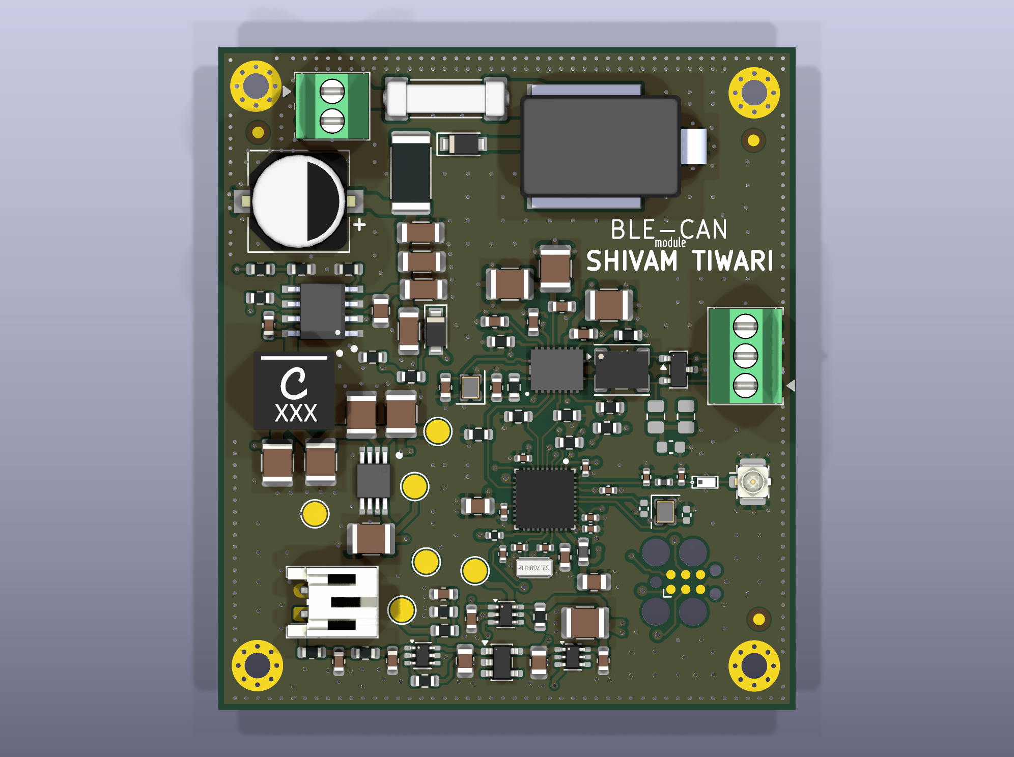
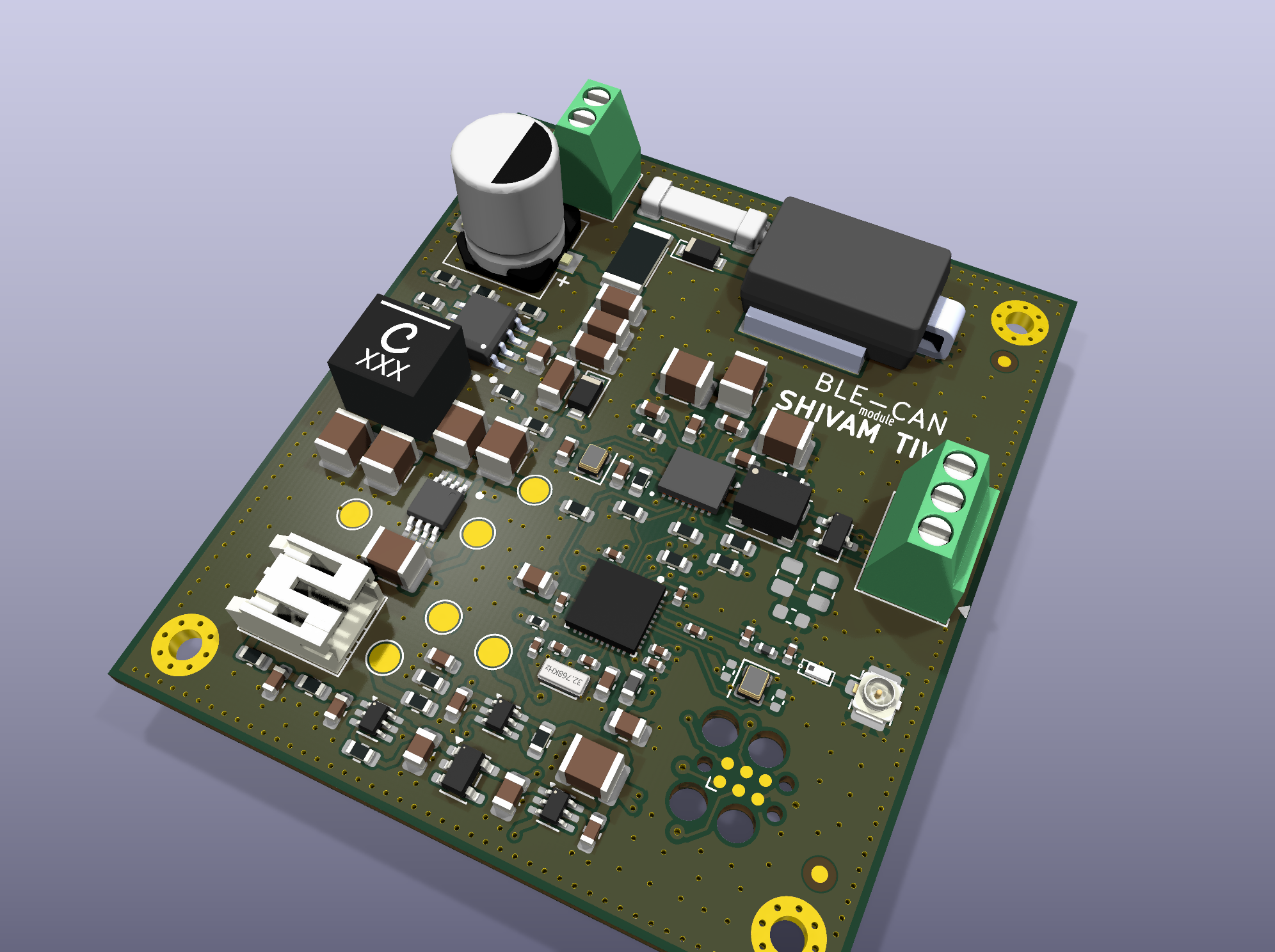
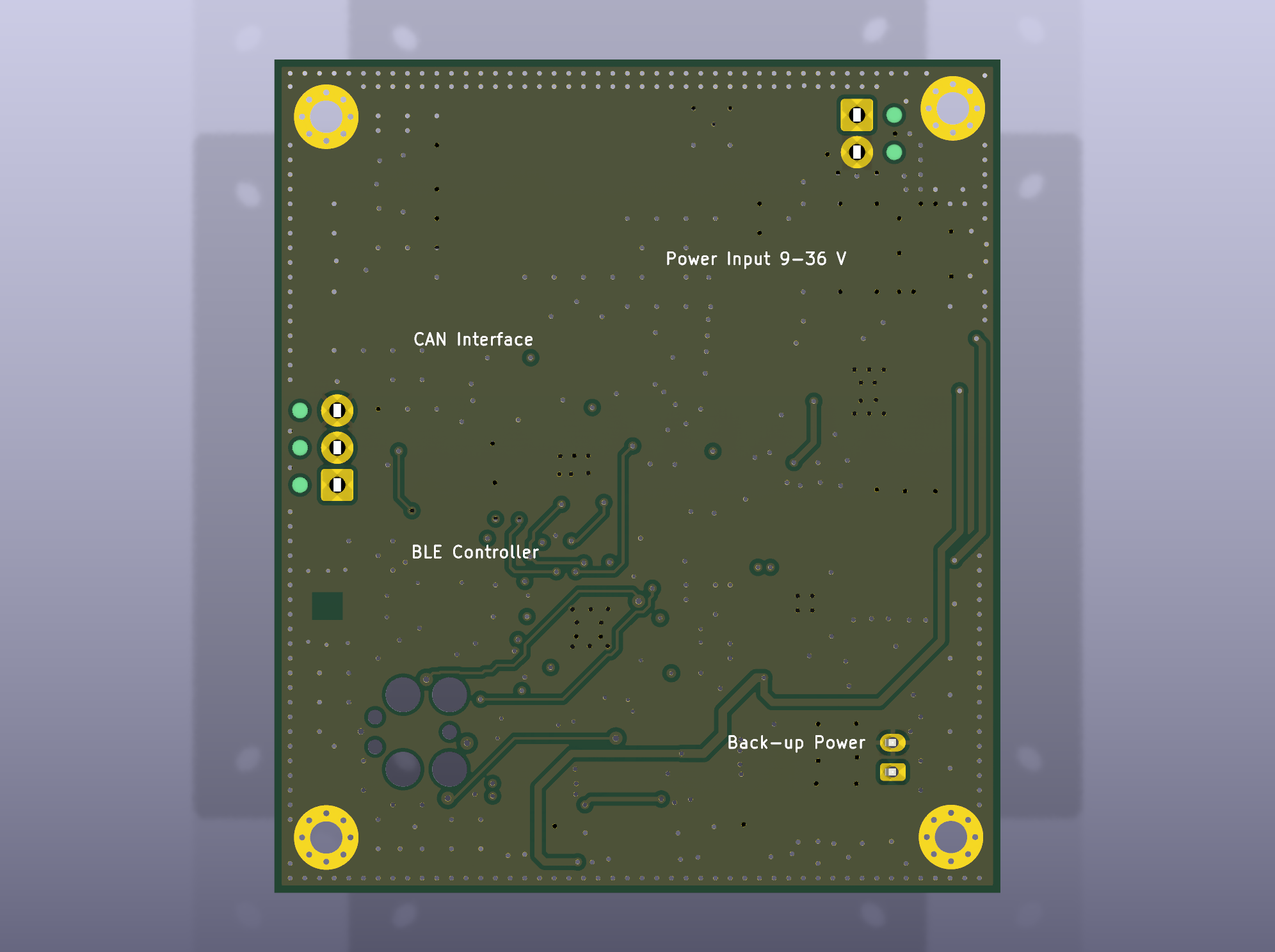
A four-layer hardware design that connects a vehicle CAN bus to a Bluetooth Low Energy (BLE) interface. The module accepts a 9–36 V vehicle supply and has a separate input for a protected, externally charged 1-cell backup battery. During backup operation, the BLE section remains powered while CAN is unavailable.
This repository is a design snapshot for review and prototyping. It has not been fabricated or electrically tested, and the open items below must be resolved before a fabrication release.
| Item | Design |
|---|---|
| Vehicle input | 9–36 V |
| CAN interface | CAN FD controller and transceiver, connected to the MCU over SPI |
| Wireless interface | Bluetooth Low Energy, with a U.FL antenna connection |
| Backup input | Protected 1-cell Li-ion pack, charged externally |
| PCB | 49.5 × 56.9 mm, four layers, single-sided component assembly |
| Design tool | KiCad 10.0.6 or later |
hardware/BLE-CAN-module.kicad_pro in KiCad 10.0.6 or later.hardware/ directory together. Its symbol tables, footprint tables, local libraries, and 3D models use project-relative paths.| Path | Contents |
|---|---|
hardware/ | Editable KiCad schematic and PCB, project-local libraries and 3D models |
hardware/Manufacturing_Output_Files/ | Gerbers, drill files, placement data, BOM, and fabrication notes |
documentation/architecture/ | System architecture and block diagram |
documentation/schematic/ | Schematic PDF |
documentation/pcb/ | PCB layer plot and 3D views |
documentation/dfmea/ | Risk register and review report |
The project includes routed PCB files and a manufacturing output package, but these are review artifacts. The architecture notes, BOM notes, and DFMEA report record the remaining assumptions and validation work.
Before fabrication, the main open items are:
nWKRQ power-domain interface in hardware.Electrical operation, vehicle transients, thermal behavior, RF performance, and EMC still require prototype testing. Do not treat the included manufacturing files as a production release.
| Qty | Value | Footprint | References |
|---|---|---|---|
| 9 | 22u / 25V | Capacitor_SMD:C_1210_3225Metric | C108, C109, C110, C111, C112, C301, C305, C310, C407 |
| 7 | 100n | Capacitor_SMD:C_0402_1005Metric | C201, C202, C203, C204, C206, C207, C215 |
| 6 | 100n / 50V | Capacitor_SMD:C_0603_1608Metric | C107, C302, C307, C308, C404, C408 |
| 4 | 100k | Resistor_SMD:R_0603_1608Metric | R307, R308, R309, R310 |
| 4 | 10k | Resistor_SMD:R_0603_1608Metric | R301, R304, R305, R306 |
| 4 | 4u7 / 100V | Capacitor_SMD:C_1206_3216Metric | C102, C103, C104, C105 |
| 4 | MountingHole_Pad | MountingHole:MountingHole_2.2mm_M2_Pad_Via | H1, H2, H3, H4 |
| 3 | 100k 1% | Resistor_SMD:R_0603_1608Metric | R103, R107, R405 |
| 3 | 1u / 16V | Capacitor_SMD:C_0603_1608Metric | C401, C402, C406 |
| 3 | Fiducial | Fiducial:Fiducial_1mm_Mask2mm | FM1, FM2, FM3 |
| 3 | LM66100QDCKRQ1 | Package_TO_SOT_SMD:SOT-363_SC-70-6 | U401, U403, U404 |
| 2 | 1.5pF | Capacitor_SMD:C_0402_1005Metric | C214, C216 |
| 2 | 10p / 50V C0G | Capacitor_SMD:C_0603_1608Metric | C303, C304 |
| 2 | 10u | Capacitor_SMD:C_0805_2012Metric | C205, C208 |
| 2 | 15p | Capacitor_SMD:C_0402_1005Metric | C212, C213 |
| 2 | 1M0 1% | Resistor_SMD:R_0603_1608Metric | R403, R404 |
| 2 | 4u7 / 25V | Capacitor_SMD:C_0805_2012Metric | C403, C405 |
| 2 | 60R4 1% DNP | Resistor_SMD:R_0805_2012Metric | R302, R303 |
| 2 | DNP | Capacitor_SMD:C_0402_1005Metric | C210, C211 |
| 2 | GND | TestPoint:TestPoint_Pad_D2.0mm | TP103, TP403 |
| 1 | 0R (tune) | Resistor_SMD:R_0603_1608Metric | R311 |
| 1 | 100K | Resistor_SMD:R_0402_1005Metric | R201 |
| 1 | 100n / 100V | Capacitor_SMD:C_0805_2012Metric | C106 |
| 1 | 10k 1% | Resistor_SMD:R_0603_1608Metric | R401 |
| 1 | 10k0 1% | Resistor_SMD:R_0603_1608Metric | R106 |
| 1 | 10u | Inductor_SMD:L_0603_1608Metric | L201 |
| 1 | 1A FF / 32V | Fuse:Fuse_0603_1608Metric | F401 |
| 1 | 1R 5% / 1W IF | Resistor_SMD:R_2512_6332Metric | R101 |
| 1 | 1S PACK 3.0-4.2V | Connector_JST:JST_PH_S2B-PH-K_1x02_P2.00mm_Horizontal | J401 |
| 1 | 1u / 10V | Capacitor_SMD:C_0603_1608Metric | C209 |
| 1 | 2.8nH | Inductor_SMD:L_0402_1005Metric | L202 |
| 1 | 22u / 100V | BLE_CAN:Panasonic_FK_F_8x10.2 | C101 |
| 1 | 2R0 1% | Resistor_SMD:R_0603_1608Metric | R402 |
| 1 | 32kHz768 | Crystal:Crystal_SMD_2012-2Pin_2.0x1.2mm | X201 |
| 1 | 383k 1% | Resistor_SMD:R_0603_1608Metric | R102 |
| 1 | 3V3_SYS | TestPoint:TestPoint_Pad_D2.0mm | TP402 |
| 1 | 3V3_VEH | TestPoint:TestPoint_Pad_D2.0mm | TP102 |
| 1 | 40MHz CL8 | Crystal:Crystal_SMD_2016-4Pin_2.0x1.6mm | X301 |
| 1 | 470n / 16V | Capacitor_SMD:C_0603_1608Metric | C306 |
| 1 | 47uH / XGL6060 | BLE_CAN:Coilcraft_XGL6060 | L101 |
| 1 | 48MHz | Crystal:Crystal_SMD_2016-4Pin_2.0x1.6mm | X202 |
| 1 | 4n7 / 50V DNP | Capacitor_SMD:C_0603_1608Metric | C309 |
| 1 | 54k9 1% | Resistor_SMD:R_0603_1608Metric | R105 |
| 1 | 64k9 1% | Resistor_SMD:R_0603_1608Metric | R104 |
| 1 | 6V5_CAN | TestPoint:TestPoint_Pad_D2.0mm | TP101 |
| 1 | 9-36 V INPUT | TerminalBlock_Phoenix:TerminalBlock_Phoenix_MPT-0,5-2-2.54_1x02_P2.54mm_Horizontal | J101 |
| 1 | ACT45B-101-2P | Inductor_SMD:L_CommonModeChoke_Coilank_ACM4532 | L301 |
| 1 | CAN BUS | TerminalBlock_Phoenix:TerminalBlock_Phoenix_MPT-0,5-3-2.54_1x03_P2.54mm_Horizontal | J301 |
| 1 | CC2340R53E0RKPR | BLE_CAN:RKP0040B-MFG | U201 |
| 1 | Conn_ARM_SWD_TagConnect_TC2030 | Connector:Tag-Connect_TC2030-IDC-FP_2x03_P1.27mm_Vertical | J202 |
| 1 | DLF162500LT-5028A1 | RF_BLE_PCBFootprints:DLF162500LT-5028A1 | FLT201 |
| 1 | LMR38010SQDDARQ1 | BLE_CAN:TI_DDA0008B_PowerPAD | U101 |
| 1 | PESD2CANFD27V | Package_TO_SOT_SMD:SOT-23 | D301 |
| 1 | PMEG10010ELR-Q | Diode_SMD:Nexperia_CFP3_SOD-123W | D103 |
| 1 | PNE20010ER-Q | Diode_SMD:Nexperia_CFP3_SOD-123W | D102 |
| 1 | SM8S40CA | BLE_CAN:Vishay_DO-218AC_SM8S | D101 |
| 1 | T1A / 125VDC | Fuse:Fuse_Schurter_UMT250 | F101 |
| 1 | TCAN4550RGYRQ1 | BLE_CAN:TI_RGY0020A_VQFN20 | U301 |
| 1 | TPS7B8133QDGNRQ1 | BLE_CAN:TI_DGN0008G_PowerPAD | U102 |
| 1 | TPS7E8130QDBVRQ1 | Package_TO_SOT_SMD:SOT-23-5 | U402 |
| 1 | U.FL-R-SMT-1 | Connector_Coaxial:U.FL_Hirose_U.FL-R-SMT-1_Vertical | J201 |
| 1 | VBAT_PROT | TestPoint:TestPoint_Pad_D2.0mm | TP401 |
bcancinov/4-channel-adc-module
4 Channel ADC module for detector controller prototype

Atif6894/automotive-ble-can-pcb
A small 4-layer board that sits on a vehicle's 12/24 V harness, talks CAN FD through a TCAN4550-Q1, and exposes it over Bluetooth LE through a CC2340R5-Q1.

Purdue-Space-Program/PSPL_R4_Avionics_Hardware
Boards and other components for R4


It measures 49.5 × 56.8 mm and has 4 copper layers, 1.58 mm thick.
110 parts, built around the CC2340R53E0RKPR, TCAN4550RGYRQ1, DLF162500LT-5028A1 and LMR38010SQDDARQ1. The full list of its parts is on this page, with links to each part's symbol and footprint where PCBKit's library has them.
From the shivamtiwari020505/Automotive-BLE-CAN-Module repository on GitHub, at the commit this page was made from: the board is hardware/BLE-CAN-module.kicad_pcb and its schematic hardware/01_POWER_INPUT.kicad_sch. PCBKit opens the board in the browser, with nothing to install.
Its repository states no licence, so its author keeps all rights: ask shivamtiwari020505 before reusing the design.