

2 layers21.9 × 15.5 mm
Multiout UFL
ThunderTechnologies/SNEdge
An open source edge sharpener for the SNES
4 parts77CERN-OHL-W-2.0

An open source edge sharpener for the SNES
SNEdge is an open-source printed circuit board by ThunderTechnologies, from the ThunderTechnologies/SNEdge repository on GitHub, published under the CERN-OHL-W-2.0 licence. It is a 2-layer board of 42.4 × 18.4 mm with 37 parts on 21 nets, routed with 257 tracks and 88 vias.
It is built around the THS7376IPW. Its parts include 15 resistors, 8 capacitors, 4 connectors and 1 IC. It belongs with the retro computing and games boards of this library.
This has only been tested on a few SNES revisions | Proceed with caution
SNEdge V2 is to a state where it can be considered stable. As SNES revisions are tested, instructions will be added to the wiki. For now, only the full bypass is supported. The sidecar install will get a dedicated design at some point.
The SNEdge corrects much of the smearing that's present on the 2 chip SNES. It taps the console's RGB, cleanly buffers it, and applies a tuned amount of sharpening to bring back the crisp edges the stock 2 chip output loses.
This is the latest revision of the SNEdge. Over the original it refines the input biasing, properly impedance-matches the outputs to the 75Ω video standard, and re-tunes the sharpening — see How It Works for the details. It still uses 0805 components, so it's relatively approachable to solder by hand.
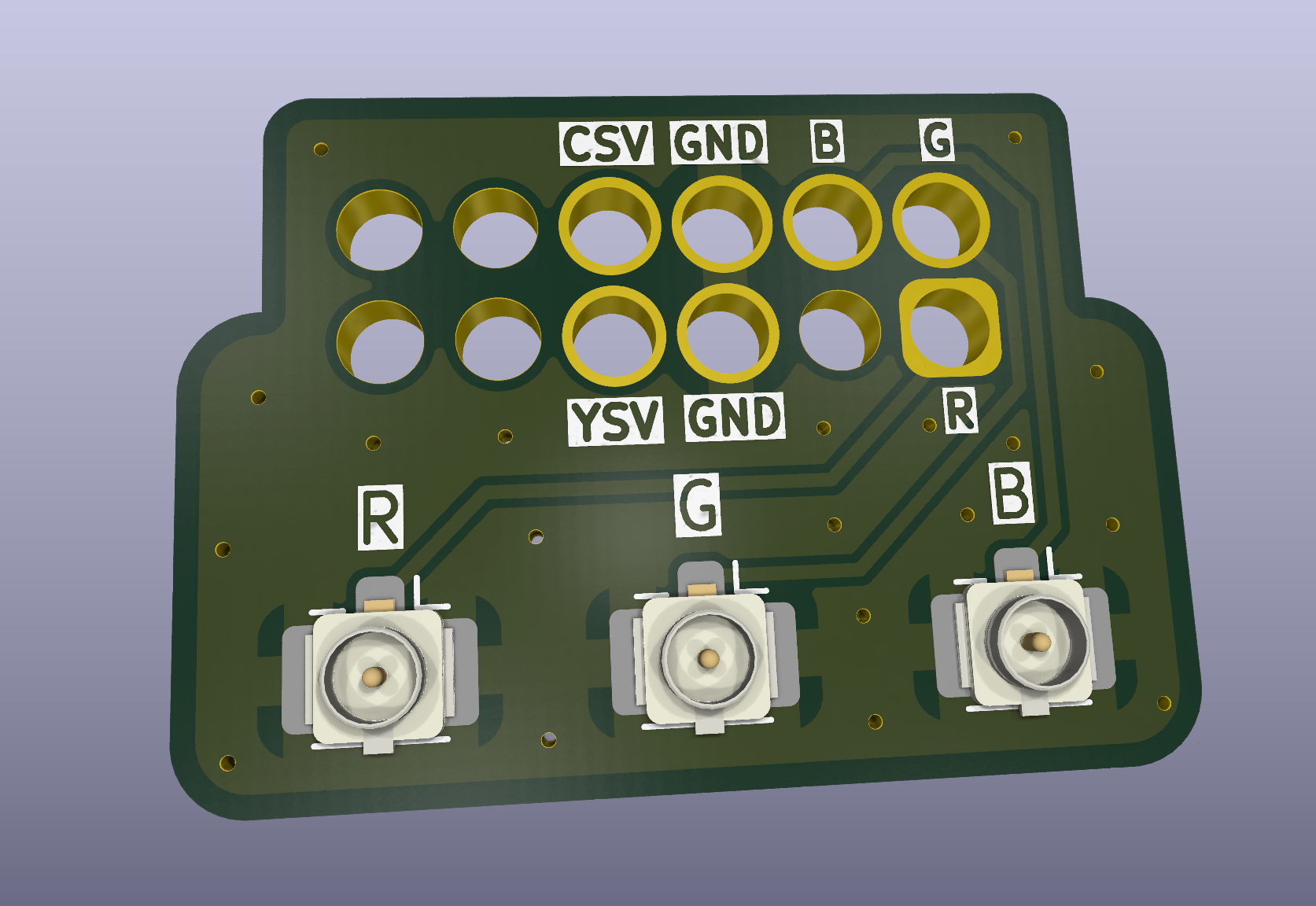
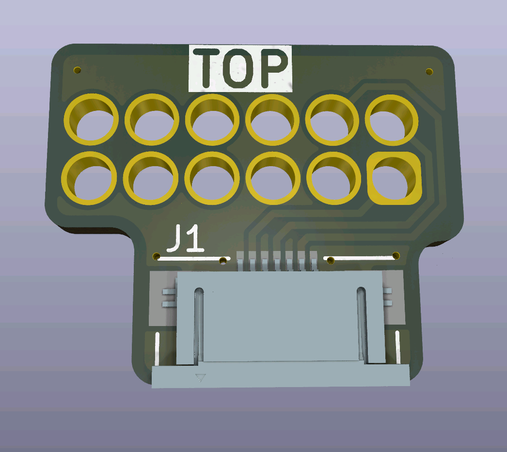
The SNEdge pairs with the Multiout QSB, which makes for a clean install right at the multiout. There are two ways to connect the SNEdge to the QSB:
Where to get the boards:
SNEdge V2 Gerbers
FFC QSB Gerbers
Coax QSB Gerbers
Note: The coax is standard U.FL 1.13mm WiFi antenna pigtail cable (roughly 10cm), widely available online.
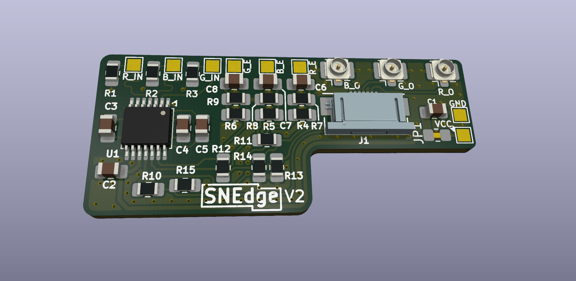
The SNEdge
The Multiout U.FL QSB
The Multiout FFC QSB
(I'll be adding screenshots of the video output soon)
The SNEdge taps the RGB video signal at the PPU2 output (the Q3/Q5/Q7 points) and runs each channel through a THS7376 video amplifier. The 2 chip SNES PPU has slow color transitions that show up on screen as smearing; cleanly buffering the signal and applying a small amount of high-frequency peaking sharpens those transitions without changing the rest of the picture.
A few design choices worth knowing about:
I don't have specific, picture instructions on how to install the SNEdge yet (These will be slowly added to the wiki).
However, looking at the SNES schematic (PDF) from wiki.superfamicom.org will be critical for understanding how to install this.
This revision installs using the RGB Bypass method, which gives the best sharpness. The older Sidecar method (which didn't require desoldering any components) is no longer supported on this revision — see A Note on the Sidecar Install below if that's what you're after.
Optionally, you can solder an additional 10uF capacitor onto C90, C91, C92, C93, and C94 on the SNES motherboard (for PAL systems, it's C91, C92, C93, C94, and C95). These help reduce video noise. They aren't required, but if you notice any noticeable noise in the output, adding them should clean it up.
Below is an SOT-23 pinout I will be referencing later.

The Sidecar method is not supported on this revision. If you want a sidecar-style install, the original SNEdge can still be used for that. A dedicated sidecar revision may be released later by ThunderTechnologies.
This revision has not been tested in a sidecar configuration. It may work fine, but it's untested, so it isn't documented as a supported install here. For this revision, use the Full RGB Bypass install below.
(Please note that PAL system installation is a bit different, I have info on this, and will be adding it eventually.)
Mount the SNEdge, keeping one priority above everything else: keep the input wires as short as possible.
The R, G, and B input wires are very sensitive to parasitic capacitance, so position the SNEdge so those wires reach their mainboard points (Q3, Q5, Q7) over the shortest distance you can manage. Keeping the input wires as close to the mainboard points as possible is the single most important part of placement. It's also preferred to keep the three input wires at similar lengths to each other.
Orientation depends on how you're connecting to the QSB:
Remove Q3, Q5, and Q7. If you only care about RGB working, remove R8, R9, R13, R14, R18, and R19. If you also care about Composite video and S-Video, also remove C6, C7, and C8.
Q3 is Red, Q5 is Green, and Q7 is Blue. Looking at the SOT-23 pinout above, pin 3 of each is ground. Pin 1 of each is the R, G, and B signals that will be soldered to the SNEdge.
Solder leads from Q3 to R_IN and GND.
Solder leads from Q5 to G_IN and GND.
Solder leads from Q7 to B_IN and GND.
The SNEdge needs to output video to U7 (S-ENC) on the SNES in order for composite video and S-video.
The SNEdge R_E, G_E, and B_E outputs go to U7's pins 20, 21, 22 respectively. (you can ignore the GND pin next to these if you'd like. If you care, connect it to pin 2 of U7.
Solder the multiout QSB on to the bottom of the SNES where the multiout pins are. If you're looking at the bottom of the SNES board, the "TOP" label on the QSB needs to be facing you. (If you're using FFC, also orient it so the FFC connector points toward the SNEdge; with coax, routing is flexible so this doesn't matter.)
The SNEdge needs 5V. Solder 5V to the + and ground to the -
Connect the SNEdge to the QSB. Coax is the recommended method:
Congrats! You have completed the full RGB bypass install. Enjoy some crispy RGB.
PAL has not been tested yet. The SNEdge should work on PAL consoles since they share the same PPU, but please treat PAL installs as experimental for now.
The main difference to be aware of is the cap designators: if you add the optional noise-reduction caps, on PAL systems they go on C91, C92, C93, C94, and C95 instead of C90-C94. PAL boards also differ around the encoder, so the Full RGB Bypass encoder connections (the U7 pin references above) may not match a PAL console one-to-one. Until PAL-specific details are confirmed and documented, treat a PAL install as experimental and proceed carefully. More complete PAL instructions will be added as they're verified.
The SNEdge is based on the work of YoshiYukiBlade over on the shmups.system11.org forums.
V2 was made possible by the many contributions from RetroLoom
| Qty | Value | Footprint | References |
|---|---|---|---|
| 4 | 1uF | Capacitor_SMD:C_0805_2012Metric_Pad1.18x1.45mm_HandSolder | C2, C6, C7, C8 |
| 3 | 10pF | Capacitor_SMD:C_0805_2012Metric_Pad1.18x1.45mm_HandSolder | C3, C4, C5 |
| 3 | 110R | Resistor_SMD:R_0805_2012Metric_Pad1.20x1.40mm_HandSolder | R13, R14, R15 |
| 3 | 240R | Resistor_SMD:R_0805_2012Metric_Pad1.20x1.40mm_HandSolder | R10, R11, R12 |
| 3 | 430R | Resistor_SMD:R_0805_2012Metric_Pad1.20x1.40mm_HandSolder | R4, R5, R6 |
| 3 | 7.5k | Resistor_SMD:R_0805_2012Metric_Pad1.20x1.40mm_HandSolder | R1, R2, R3 |
| 3 | 75R | Resistor_SMD:R_0805_2012Metric_Pad1.20x1.40mm_HandSolder | R7, R8, R9 |
| 1 | 22uF | Capacitor_SMD:C_0805_2012Metric_Pad1.18x1.45mm_HandSolder | C1 |
| 1 | B_E | TestPoint:TestPoint_Pad_1.5x1.5mm | TP7 |
| 1 | B_IN | TestPoint:TestPoint_Pad_1.5x1.5mm | TP4 |
| 1 | B_O | Connector_Coaxial:U.FL_Hirose_U.FL-R-SMT-1_Vertical | J9 |
| 1 | GND | TestPoint:TestPoint_Pad_1.5x1.5mm | TP2 |
| 1 | G_E | TestPoint:TestPoint_Pad_1.5x1.5mm | TP8 |
| 1 | G_IN | TestPoint:TestPoint_Pad_1.5x1.5mm | TP3 |
| 1 | G_O | Connector_Coaxial:U.FL_Hirose_U.FL-R-SMT-1_Vertical | J8 |
| 1 | INPUT JUMPER | TT_Jumpers:R_0805_2012Metric_Pad1.20x1.40mm_HandSolder_Jumper_Closed | JP1 |
| 1 | RGB_OUT | TT_Connectors:CON_527460771_MOL | J1 |
| 1 | R_E | TestPoint:TestPoint_Pad_1.5x1.5mm | TP6 |
| 1 | R_IN | TestPoint:TestPoint_Pad_1.5x1.5mm | TP5 |
| 1 | R_O | Connector_Coaxial:U.FL_Hirose_U.FL-R-SMT-1_Vertical | J10 |
| 1 | THS7376 | Package_SO:TSSOP-14_4.4x5mm_P0.65mm | U1 |
| 1 | VCC | TestPoint:TestPoint_Pad_1.5x1.5mm | TP1 |
ThunderTechnologies/SNEdge
An open source edge sharpener for the SNES

ThunderTechnologies/SNEdge
An open source edge sharpener for the SNES

yoonjustin/WinchesterPCB
Open source JAMMA supergun project. KiCAD PCB design files

RetroLoom/HKTV13RGB
Open-hardware RGB mod for the Emerson HKTV13 "Hello Kitty" CRT TV — an interposer board that injects switchable external RGB while preserving the original OSD.


hoglet67/RGBtoHDMI
Bare-metal Raspberry Pi project that provides pixel-perfect sampling of Retro Computer RGB/YUV video and conversion to HDMI

hackclub/OnBoard
💡 Join 1,000 teenagers and make your first PCB with a $100 grant!

FreeYourStream/freedeck-hardware
all the stuff you need to build your own FreeDeck

stuartpittaway/diyBMS
Do it yourself battery management system for Lithium ion battery packs/cells

Pwnsat/FlatSat
Flatsat v1.0 is a hardware based platform for aerospace cybersecurity research
It measures 42.4 × 18.4 mm and has 2 copper layers, 1.6 mm thick.
37 parts, built around the THS7376IPW. The full list of its parts is on this page, with links to each part's symbol and footprint where PCBKit's library has them.
From the ThunderTechnologies/SNEdge repository on GitHub, at the commit this page was made from: the board is SNEdge PCB/SNEdge.kicad_pcb and its schematic Multi AV QSB/FFC QSB/Multiout_FFC.kicad_sch. PCBKit opens the board in the browser, with nothing to install.
Its repository publishes it under the CERN-OHL-W-2.0 licence: you may reuse it on that licence's terms (keep the author's notice, and for a copyleft licence share your changes alike).