
2 layers42.4 × 18.4 mm

 RetroLoom/HKTV13RGB
Open-hardware RGB mod for the Emerson HKTV13 "Hello Kitty" CRT TV — an interposer board that injects switchable external RGB while preserving the original OSD.
HKTV13RGB is an open-source printed circuit board by RetroLoom, from the RetroLoom/HKTV13RGB repository on GitHub, published under the CERN-OHL-S-2.0 licence. It is a 2-layer board of 55.9 × 37.2 mm with 35 parts on 35 nets, routed with 196 tracks and 117 vias.
It is built around the THS7376IPW, AMS1117-5.0 and LL4148. Its parts include 17 resistors, 7 capacitors, 3 ICs, 3 connectors and 1 diode. It belongs with the lEDs and displays and retro computing and games boards of this library.


An open-hardware RGB injection board that adds clean, switchable RGB input to the Emerson HKTV13 Hello Kitty CRT television. The module is an interposer that sits between the TV's neck board and main board, in line with the existing 7-pin OSD link. It either passes the original OSD signals straight through, or pulls them out and injects external RGB in their place — letting you feed RGB from a retro console, scaler, or other source while keeping the set's original on-screen display (OSD) fully usable.
⚠️ High-voltage warning. CRT televisions contain lethal voltages that can remain present even when unplugged. The CRT anode and the chassis around it can hold a dangerous charge for a long time. Do not attempt this mod unless you understand how to safely discharge and work inside a CRT. You perform this modification entirely at your own risk.
Unusually, the HKTV13 has two OSD generators — one of them lives on the neck
board and sends its OSD to the main board (the jungle/tube-driver chip) over a
7-pin connector (P502). Because of that dual-OSD design, the TV already has its own
internal, buffered switching circuit between the two OSD sources, and there is no
clean point to mux external RGB into it.
This mod takes a different approach. It inserts itself into the neck-board OSD link as an interposer and switches the whole path out rather than muxing:
The result is a sharp RGB picture on the original Hello Kitty CRT, with the stock OSD/normal signal fully restored when you switch back. Because the board sits in the existing signal path with the same 7-pin pinout on both sides, it can be bypassed by simply unplugging it and reconnecting the neck board to the main board directly (see Bypass / reversibility).
The external RGB harness is wired compatible with the Sunthar / "Sunthar-style" RGB pinout, so existing SCART/RGB cables built to that convention will work.
| Block | Part | Role |
|---|---|---|
| Video amplifier | THS7376 | Buffers/level-shifts the RGB and drives it into the jungle chip. |
| Path switch | TS5V330 analog switch | Switches the whole path between the original OSD/normal signal and external RGB. |
| Power regulator | AMS1117-5.0 LDO | Provides 5 V (VCC) for the board from the TV's OSD_10v rail. |
| Blanking gate | JP1 + R10 + LL4148 | Conditions the Fast Blanking signal that drives the switch. |
Fast Blanking can be sourced externally (e.g. SCART pin 16, for sources that
drive their own blanking) or internally via the on-board switch — useful for
sources that don't supply F_BLK. Each RGB input is terminated at 75 Ω and
AC-coupled (100 nF) on the way in, then re-biased after the amplifier. The full
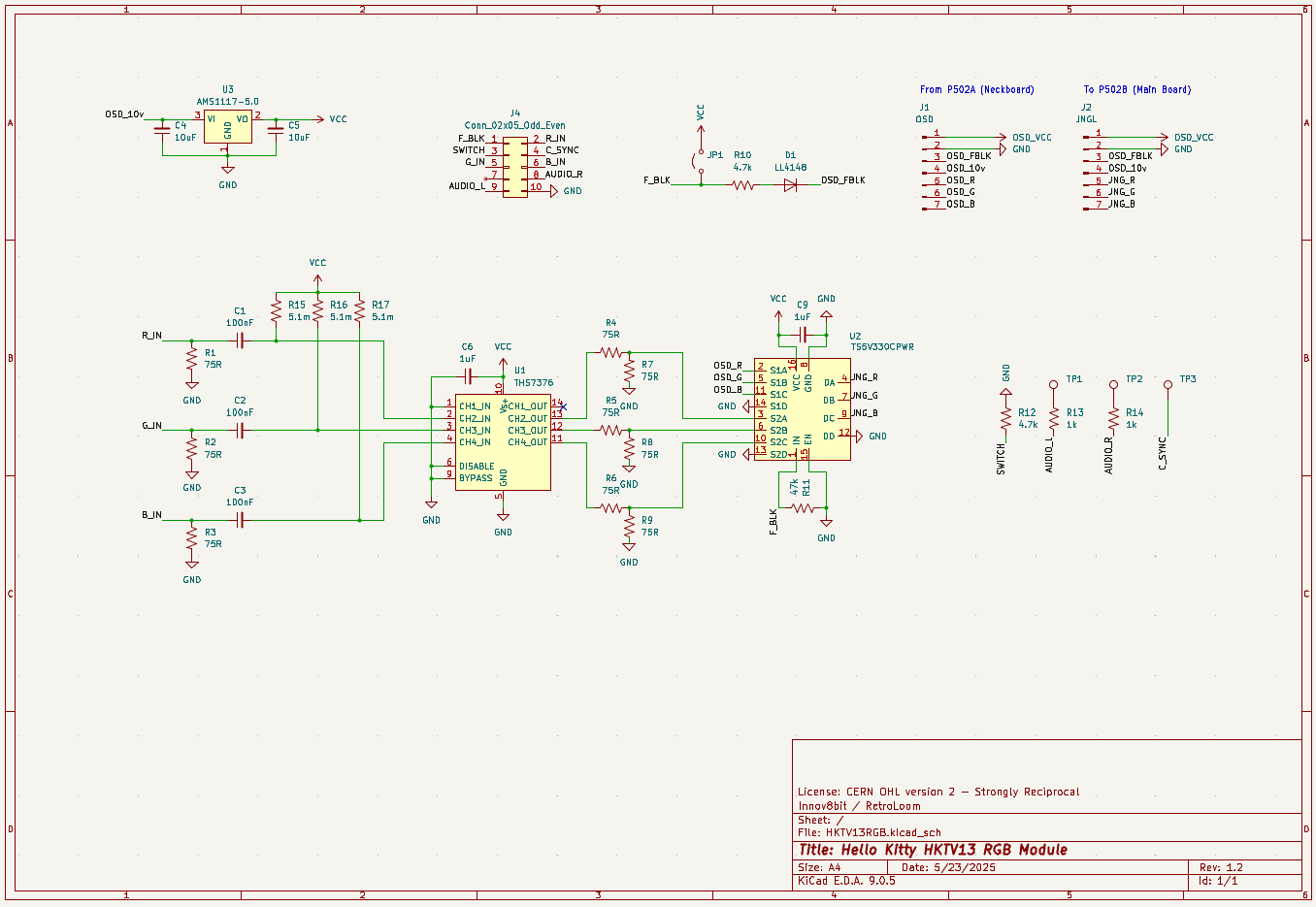
schematic is in
images/schematic.png (PDF: images/schematic.pdf)
and the editable source is in the KiCad/ folder.
 |  |
 |  |
HKTV13RGB/
├── KiCad/
│   ├── HKTV13RGB.kicad_pro       # KiCad 9 project
│   ├── HKTV13RGB.kicad_sch       # Schematic
│   ├── HKTV13RGB.kicad_pcb       # PCB layout
│   ├── Project Symbols.kicad_sym # Custom symbols
│   └── Gerbers/
│       ├── HKTV13RGB v1.0.zip    # Ready-to-order fabrication package
│       └── *.gbr / *.drl         # Individual Gerber + drill files
├── images/                       # Build & install photos, schematic
├── LICENSE                       # CERN-OHL-S v2
└── README.mdTo open the design, install KiCad (9.0 or newer) and open
KiCad/HKTV13RGB.kicad_pro.
Pin numbering is taken from the schematic in
images/schematic.png. Confirm against your board silkscreen before wiring.
J4 — Main I/O (2×5 header)
| Pin | Signal | Pin | Signal |
|---|---|---|---|
| 1 | F_BLK (Fast Blanking in) | 2 | R_IN |
| 3 | SWITCH | 4 | C_SYNC |
| 5 | G_IN | 6 | B_IN |
| 7 | GND | 8 | AUDIO_R |
| 9 | AUDIO_L | 10 | GND |
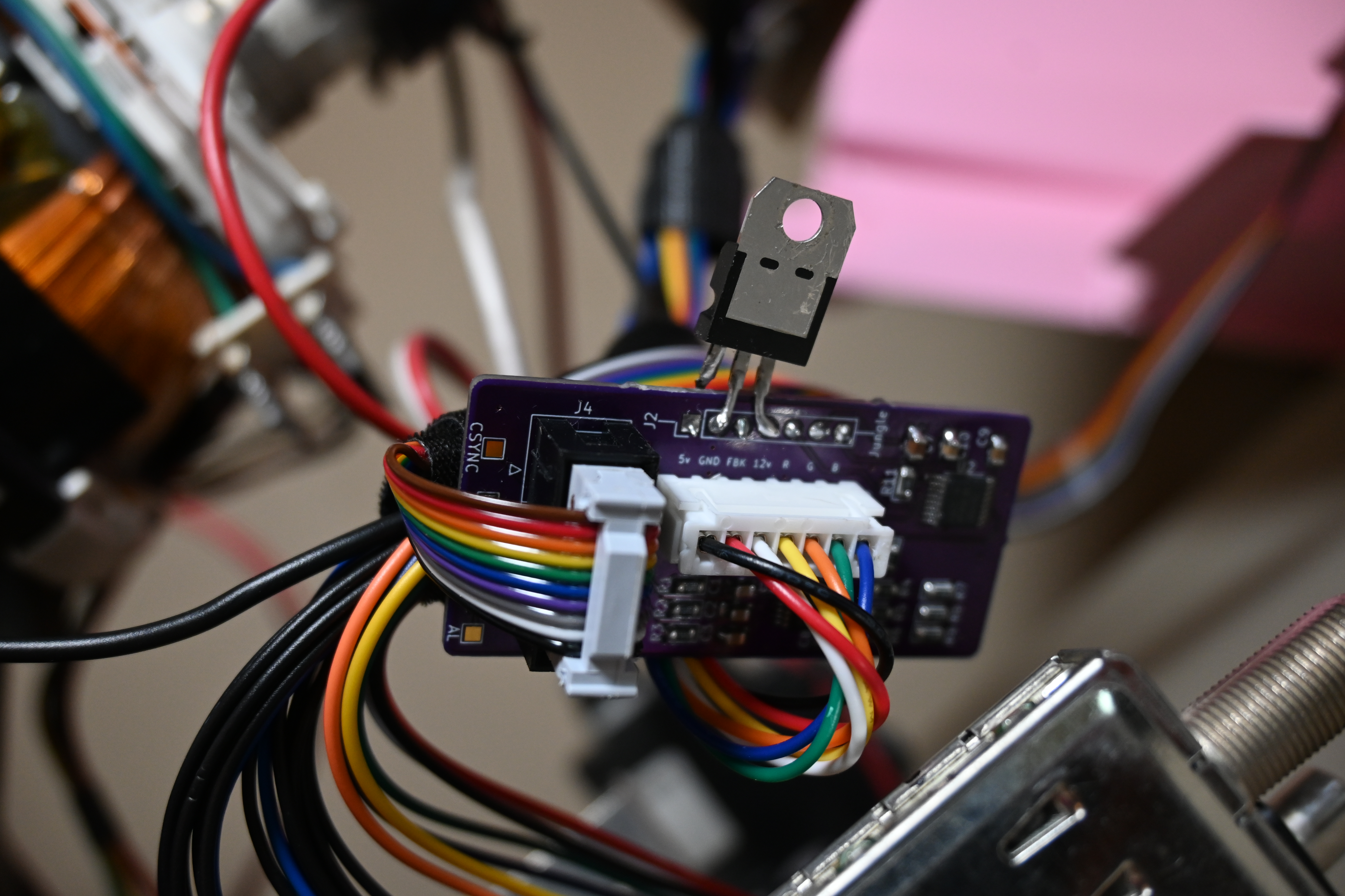
J1 — "OSD" (from the neck board) — silkscreened OSD. Carries the original secondary OSD signals coming off the neck board. A 7-pin 2.54 mm JST socket is soldered here so the neck-board cable plugs straight in.
| Pin | Signal |
|---|---|
| 1 | OSD_FBLK |
| 2 | OSD_VCC |
| 3 | OSD_10v (board power source) |
| 4 | OSD_R |
| 5 | OSD_G |
| 6 | OSD_B |
| 7 | GND |
J2 — "JNG" (to the main board) — silkscreened JNG. Sends the selected signal
(pass-through OSD or injected RGB) on to the main board. A 7-pin wire harness is
soldered to the underside here and terminates in a plug for the main board's
P502.
| Pin | Signal |
|---|---|
| 1 | DSD_FBLK |
| 2 | DSD_VCC |
| 3 | DSD_10v |
| 4 | JNG_R |
| 5 | JNG_G |
| 6 | JNG_B |
| 7 | GND |
JP1 — Fast Blanking enable jumper. Gates the F_BLK signal into the OSD switch.
Test points
These pass audio and composite sync through to the main board. They are optional —
not required for the RGB picture itself. In a typical install, sync for the picture is
supplied by the TV's own composite input, not by the module's C_SYNC. (If you're
feeding the set over SCART, you may instead pass C_SYNC / composite through here.)
| TP | Signal |
|---|---|
| TP1 | AUDIO_R |
| TP2 | AUDIO_L |
| TP3 | C_SYNC |
| Ref | Value / Part | Notes |
|---|---|---|
| U1 | THS7376 | Video amplifier |
| U2 | TS5V330CPWR (TSSOP-16) | Analog switch (path select) |
| U3 | AMS1117-5.0 | 5 V LDO regulator |
| D1 | LL4148 | Switching diode (MiniMELF) |
| C1–C3 | 100 nF | RGB input AC coupling |
| C4, C5 | 10 µF | LDO input / output |
| C6, C9 | 1 µF | Decoupling |
| R1–R9 | 75 Ω | Video termination / series |
| R10 | 4.7 kΩ | F_BLK pull |
| R11 | 47 kΩ | F_BLK pull-down |
| R12 | 4.7 kΩ | SWITCH pull |
| R13, R14 | 1 kΩ | Audio series |
| R15–R17 | 5.1 kΩ | Bias pull-ups for the THS7376 inputs |
Exact values and footprints are authoritative in the KiCad schematic.
The fastest path is to upload the prebuilt package
KiCad/Gerbers/HKTV13RGB v1.0.zip directly to any PCB fab
(JLCPCB, PCBWay, OSH Park, etc.). Standard 2-layer, 1.6 mm, 1 oz copper settings
are fine. The individual Gerber and drill files are alongside the zip if you'd
rather supply them separately.
Take photos of every connector and wire you touch before you disconnect anything. Work on a non-conductive surface and keep one hand behind your back when the set is powered.
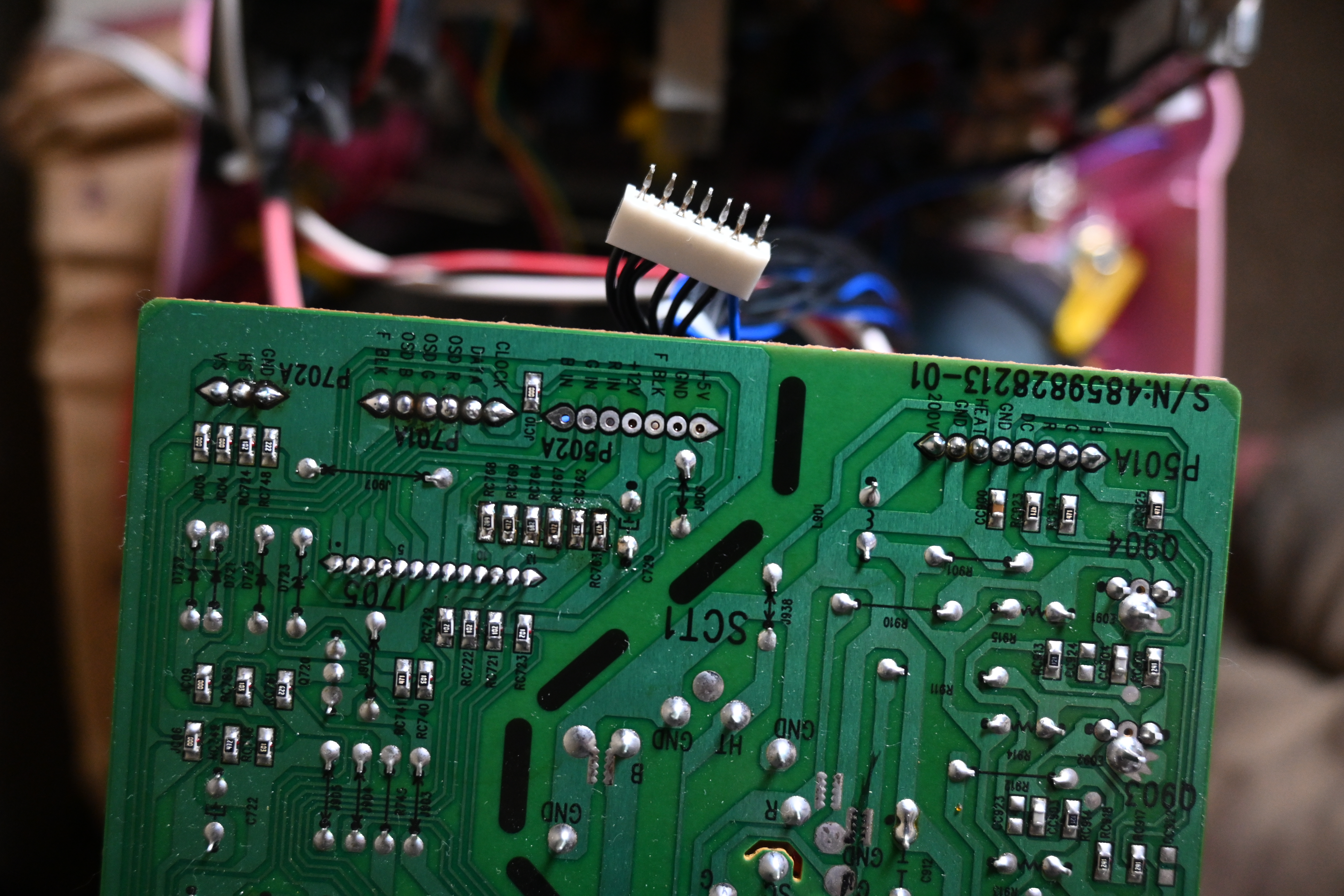
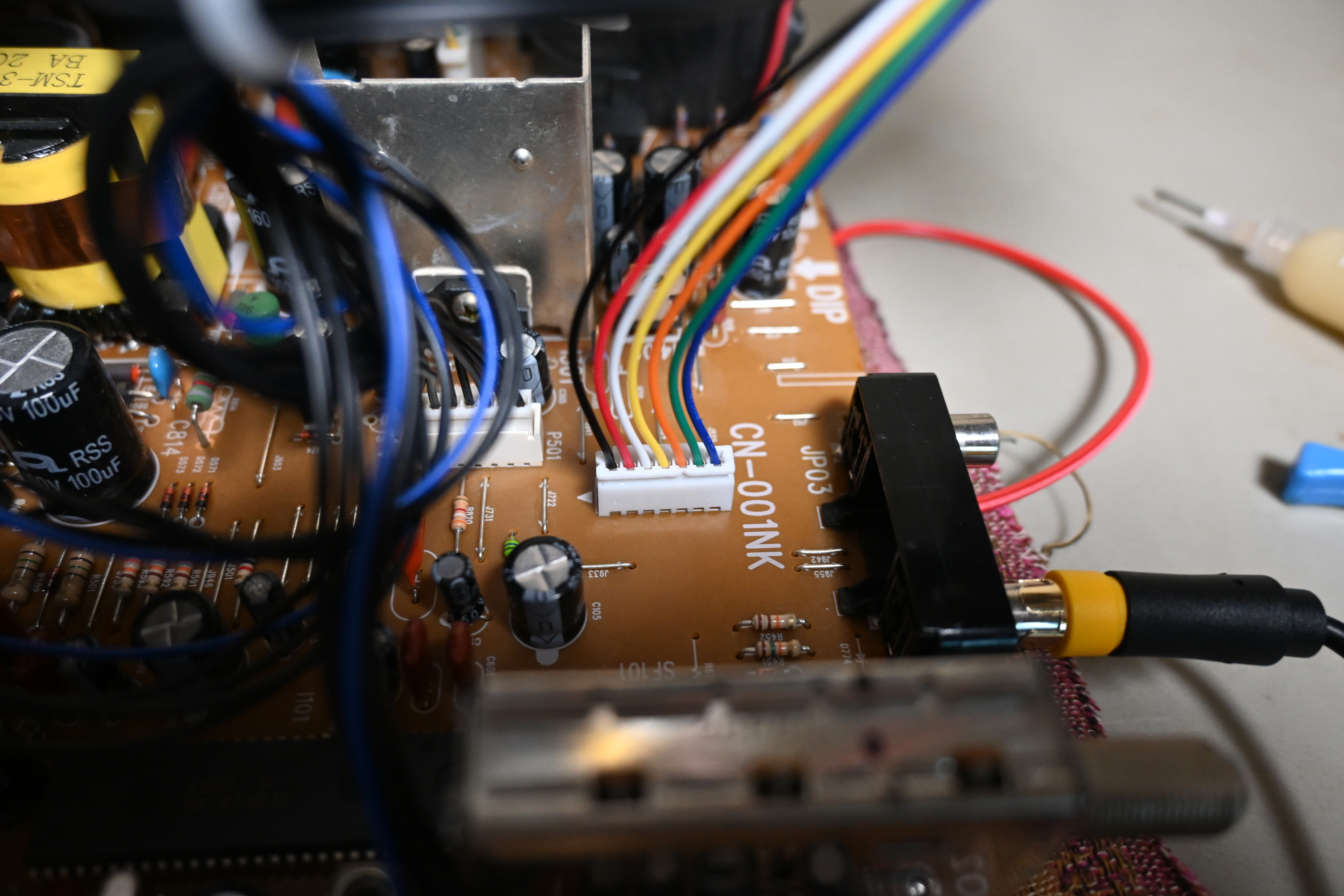
The mod installs in line with the existing neck-board ↔ main-board OSD link. You'll convert both ends of that link to a 7-pin 2.54 mm JST connection so the module can drop in (and out) cleanly.
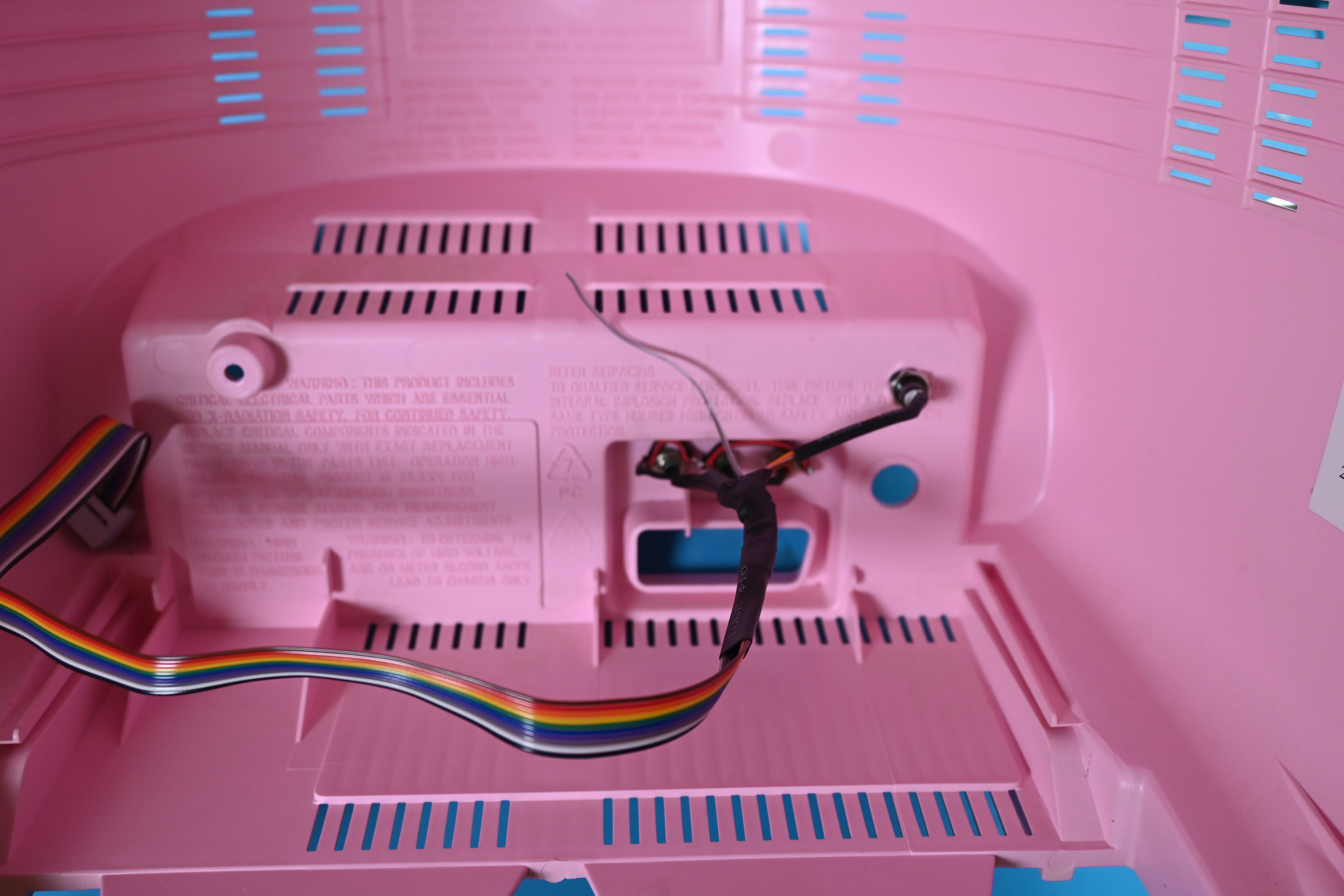
P502 on the main board with a
7-pin 2.54 mm-pitch JST socket. This lets the neck board and main board
connect normally again without the mod, and gives the module's JNG harness
a place to plug in.
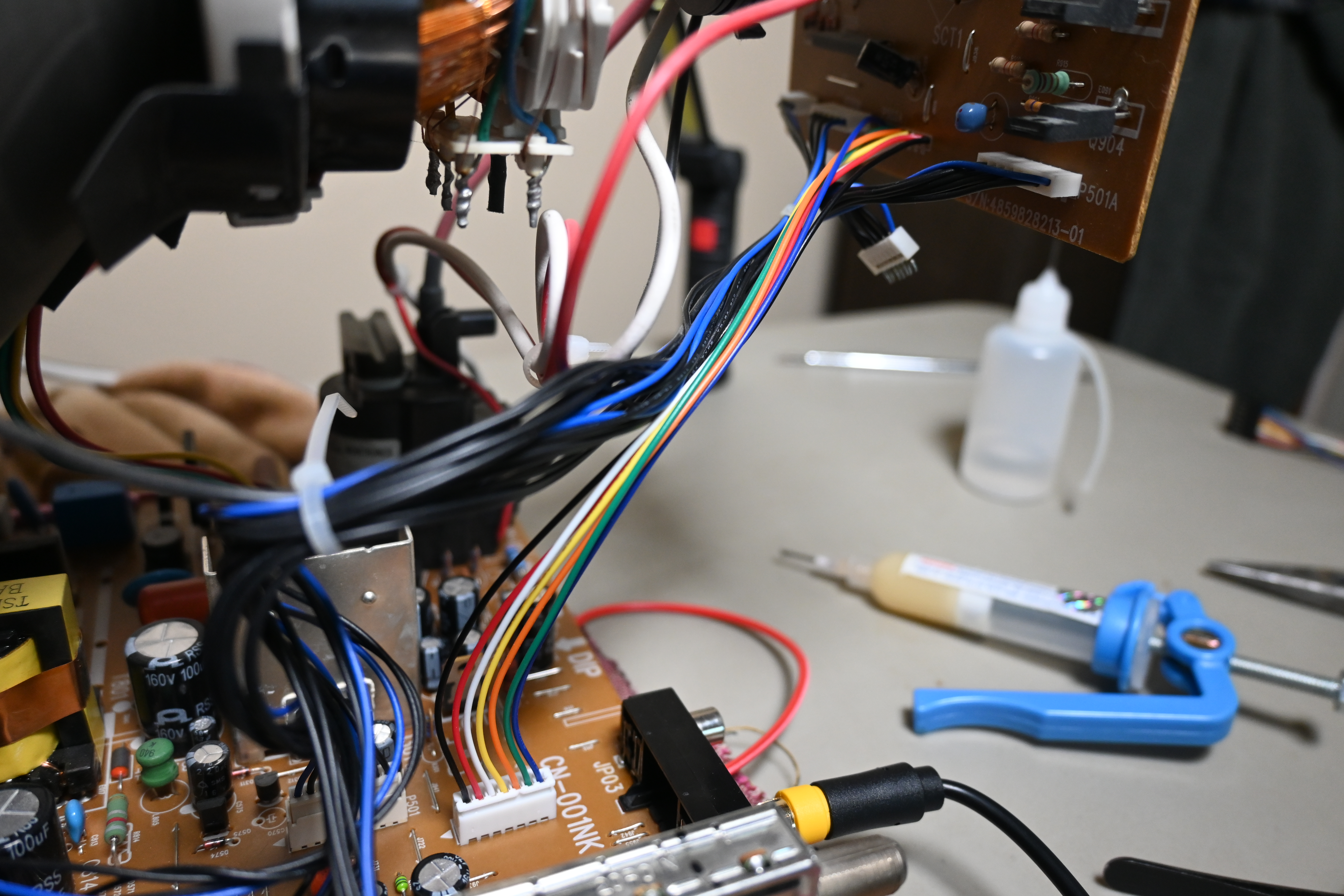
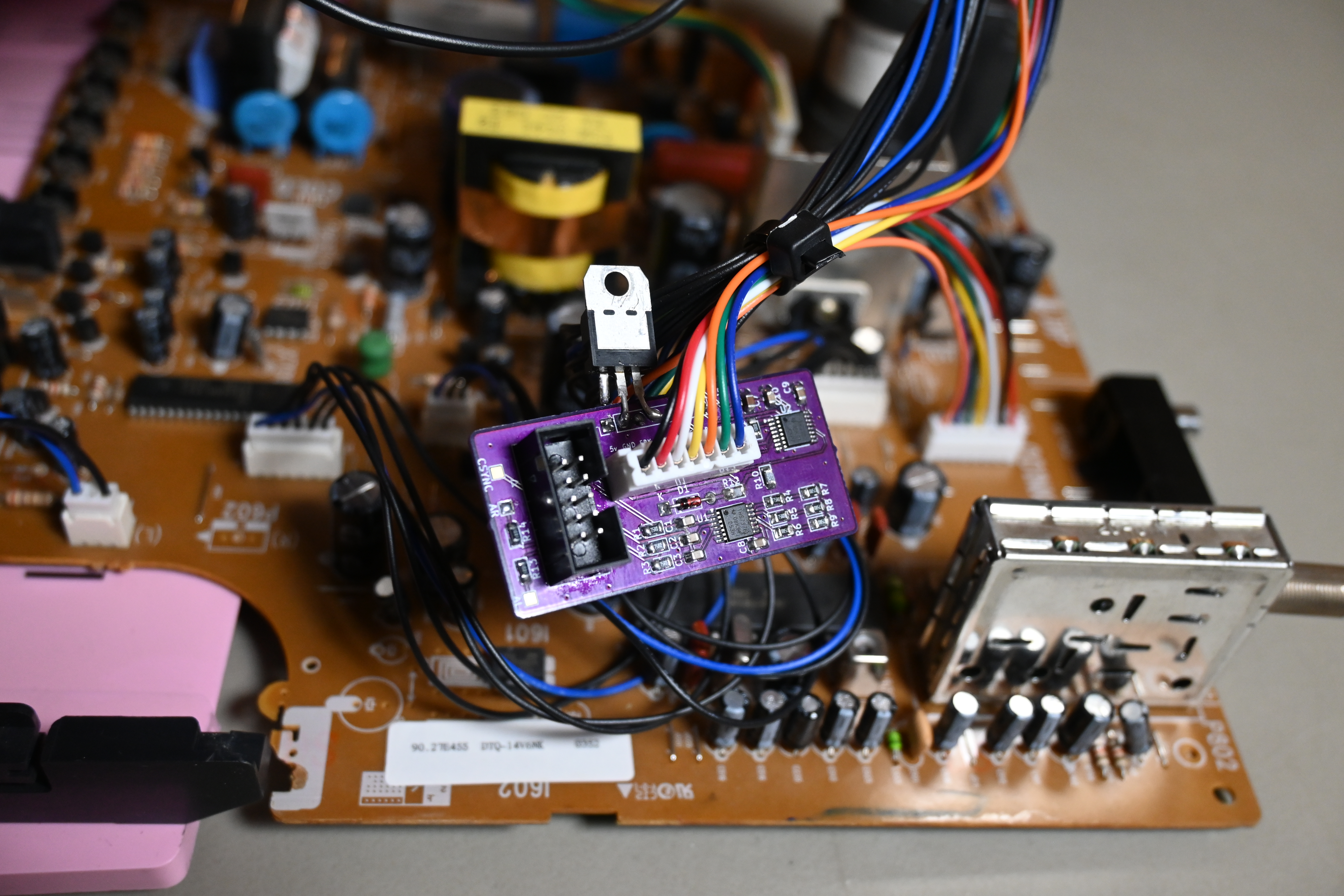
P502 JST socket on the main board.P502 socket. The board is
now powered from OSD_10v (regulated to 5 V on-board) and is interposed in the
OSD path.
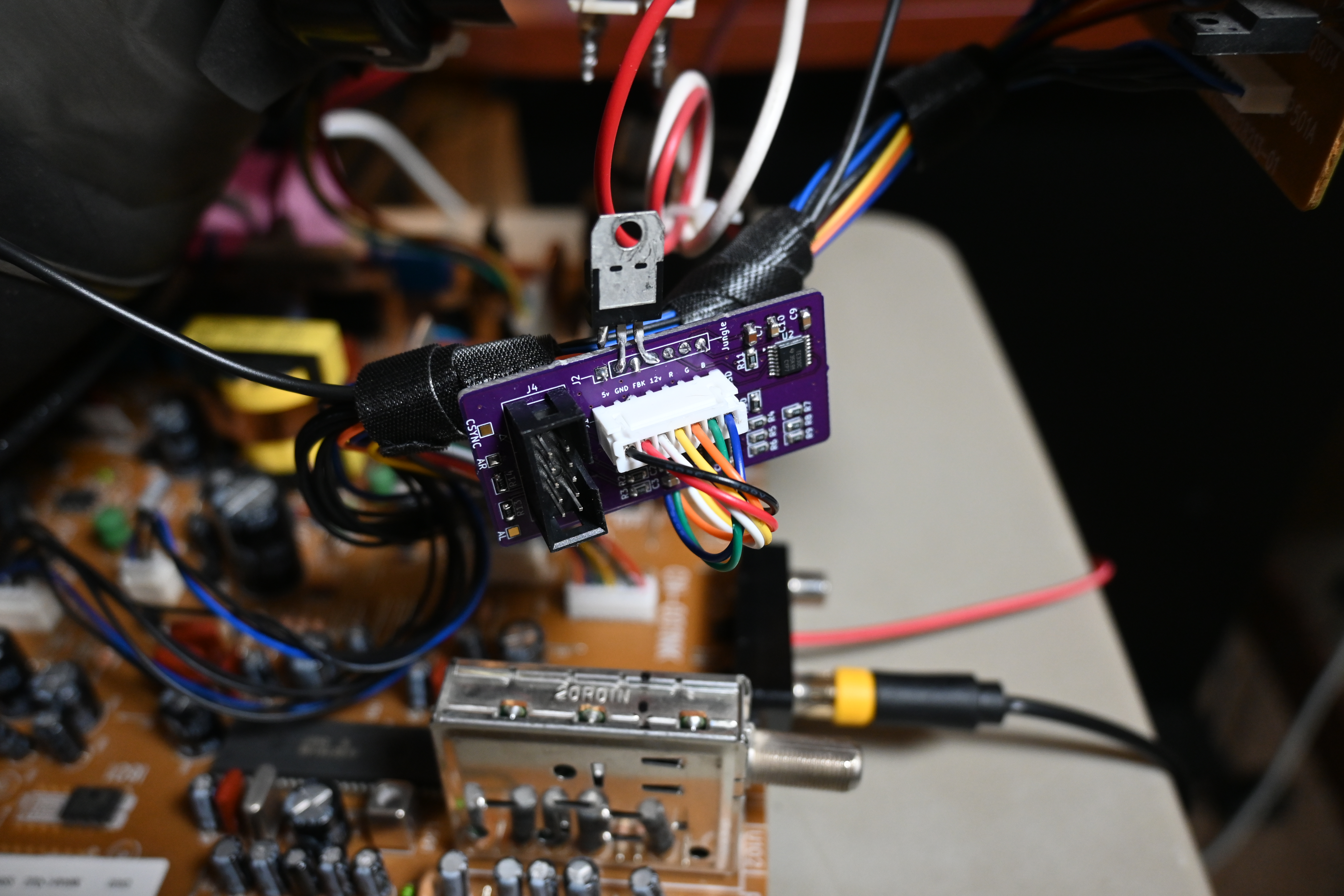
JP1 accordingly.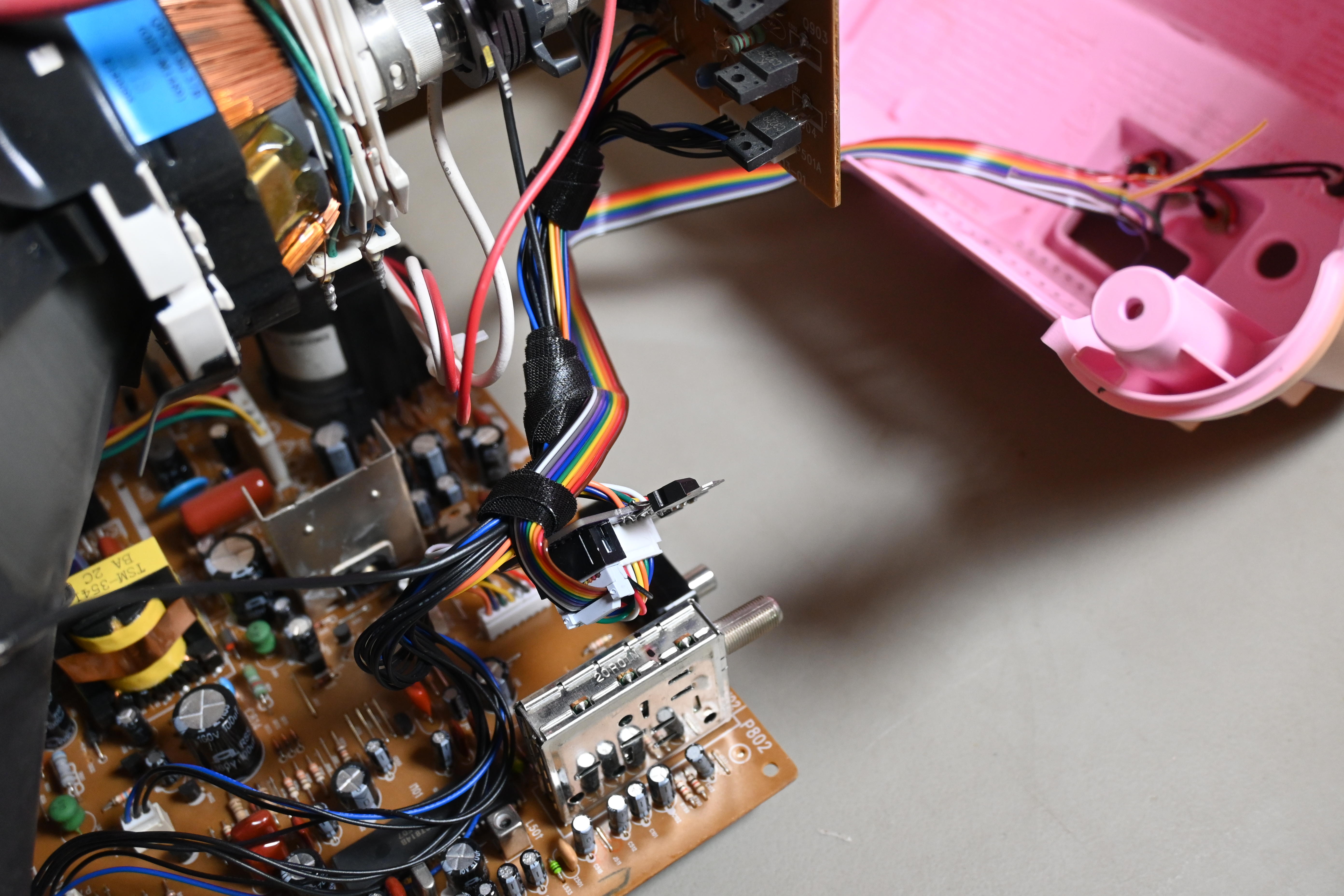
Additional reference photos of the install are in the images/ folder.
Because the module sits in the existing OSD link with the same 7-pin pinout on both sides, it can be removed without any further modification to the set:
P502 socket.P502 socket.The TV is now back to stock behavior. The only permanent change is the swap to JST
connectors on the neck-board cable and P502 — the mod itself is fully removable.
OSD_FBLK on J1, F_BLK on J4)
is the first thing to check.C_SYNC) to probe signals if something looks wrong.
These are pass-through/optional — sync for the picture normally comes from the TV's
composite input, not the module's C_SYNC.| Symptom | Likely cause |
|---|---|
| No picture at all | No board power — check OSD_10v into J1 and ground; verify 5 V at the AMS1117 output. |
| RGB shows but OSD/menus gone | Fast Blanking not returning to OSD — check the internal/external F_BLK switch, JP1, OSD_FBLK, and F_BLK wiring. |
| OSD shows but no external RGB | Switch never engages — check the F_BLK source (try internal switch), SWITCH line, and RGB input wiring on J4. |
| Picture works only when mod removed | Re-check OSD/JNG plug orientation; confirm P502 JST pinout matches the original cable. |
| Weak / washed-out colors | Termination/coupling issue — verify the 75 Ω inputs and RGB ground return. |
| Rolling / unstable image | Sync problem — sync normally comes from the TV's composite input, so check that first; only check C_SYNC on J4 (TP3) if you're passing sync via SCART. |
| No audio | Check AUDIO_L / AUDIO_R on J4 (TP1/TP2) and series resistors R13/R14. |
This project is released under the CERN Open Hardware Licence Version 2 —
Strongly Reciprocal (CERN-OHL-S v2). See LICENSE for the full text.
You are free to use, study, modify, and redistribute the design under its terms;
derivatives must be shared under the same license.
This is a community modification and is not affiliated with or endorsed by Emerson or Sanrio. "Hello Kitty" and related marks are property of their respective owners.
| Qty | Value | Footprint | References |
|---|---|---|---|
| 9 | 75R | Resistor_SMD:R_0805_2012Metric_Pad1.20x1.40mm_HandSolder | R1, R2, R3, R4, R5, R6, R7, R8, R9 |
| 3 | 100nF | Capacitor_SMD:C_0805_2012Metric_Pad1.18x1.45mm_HandSolder | C1, C2, C3 |
| 3 | 5.1m | Resistor_SMD:R_0805_2012Metric_Pad1.20x1.40mm_HandSolder | R15, R16, R17 |
| 2 | 10uF | Capacitor_SMD:C_0805_2012Metric_Pad1.18x1.45mm_HandSolder | C4, C5 |
| 2 | 1k | Resistor_SMD:R_0805_2012Metric_Pad1.20x1.40mm_HandSolder | R13, R14 |
| 2 | 1uF | Capacitor_SMD:C_0805_2012Metric_Pad1.18x1.45mm_HandSolder | C6, C9 |
| 2 | 4.7k | Resistor_SMD:R_0805_2012Metric_Pad1.20x1.40mm_HandSolder | R10, R12 |
| 1 | 47k | Resistor_SMD:R_0805_2012Metric_Pad1.20x1.40mm_HandSolder | R11 |
| 1 | AL | TestPoint:TestPoint_Pad_1.5x1.5mm | TP1 |
| 1 | AMS1117-5.0 | Package_TO_SOT_SMD:SOT-223-3_TabPin2 | U3 |
| 1 | AR | TestPoint:TestPoint_Pad_1.5x1.5mm | TP2 |
| 1 | CSYNC | TestPoint:TestPoint_Pad_1.5x1.5mm | TP3 |
| 1 | Conn_02x05_Odd_Even | Connector_IDC:IDC-Header_2x05_P2.54mm_Vertical | J4 |
| 1 | FB - VCC | Jumper:SolderJumper-2_P1.3mm_Open_RoundedPad1.0x1.5mm | JP1 |
| 1 | JNGL | Connector_PinHeader_2.54mm:PinHeader_1x07_P2.54mm_Vertical | J2 |
| 1 | LL4148 | Diode_SMD:D_MiniMELF | D1 |
| 1 | OSD | Connector_PinHeader_2.54mm:PinHeader_1x07_P2.54mm_Vertical | J1 |
| 1 | THS7376 | Package_SO:TSSOP-14_4.4x5mm_P0.65mm | U1 |
| 1 | TS5V330CPWR | Package_SO:TSSOP-16_4.4x5mm_P0.65mm | U2 |

yoonjustin/WinchesterPCB
Open source JAMMA supergun project. KiCAD PCB design files

ZeniteSolar/MSC22
Atalização do Módulo Sensor Can 19 https://github.com/ZeniteSolar/MSC19 Agora com alimentação bipolar +/- 15V para os sensores. Estágio analógico devidamente ajustado.

danielsimonreinhardt/microHIL
microHIL is a self-developed testing device for setting up a basic hardware-in-the-loop environment

kwiecinski/BMS-and-offgrid-photovoltaic-management-system
Project contains BMS for lead-acid batteries and ESP-based board used to pull information from EASUN offgrid inverter, energy meters and sensors.

ChrisChrisLoLo/beyblock20
The magnetic, modular, 20-key macropad that can join together to form an ortholinear board

JGAguado/Smart_Plant
The Smart Plant is a board that can be plugged directly on the soil, close to the plant, that allows the measurement of the environment (soil moisture, environment temperature & illuminance), and presents the…

It measures 55.9 × 37.2 mm and has 2 copper layers, 1.6 mm thick.
35 parts, built around the THS7376IPW, AMS1117-5.0 and LL4148. The full list of its parts is on this page, with links to each part's symbol and footprint where PCBKit's library has them.
From the RetroLoom/HKTV13RGB repository on GitHub, at the commit this page was made from: the board is KiCad/HKTV13RGB.kicad_pcb and its schematic KiCad/HKTV13RGB.kicad_sch. PCBKit opens the board in the browser, with nothing to install.
Its repository publishes it under the CERN-OHL-S-2.0 licence: you may reuse it on that licence's terms (keep the author's notice, and for a copyleft licence share your changes alike).