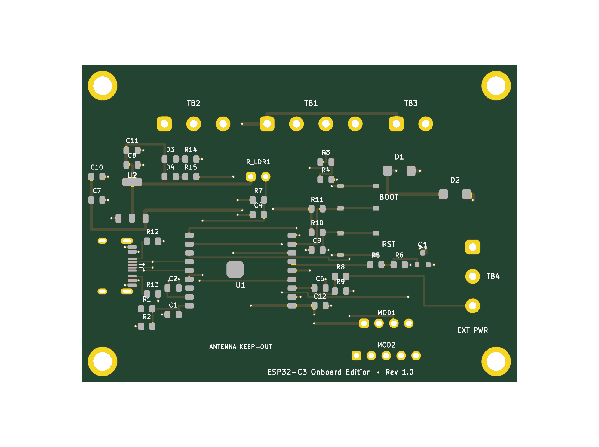
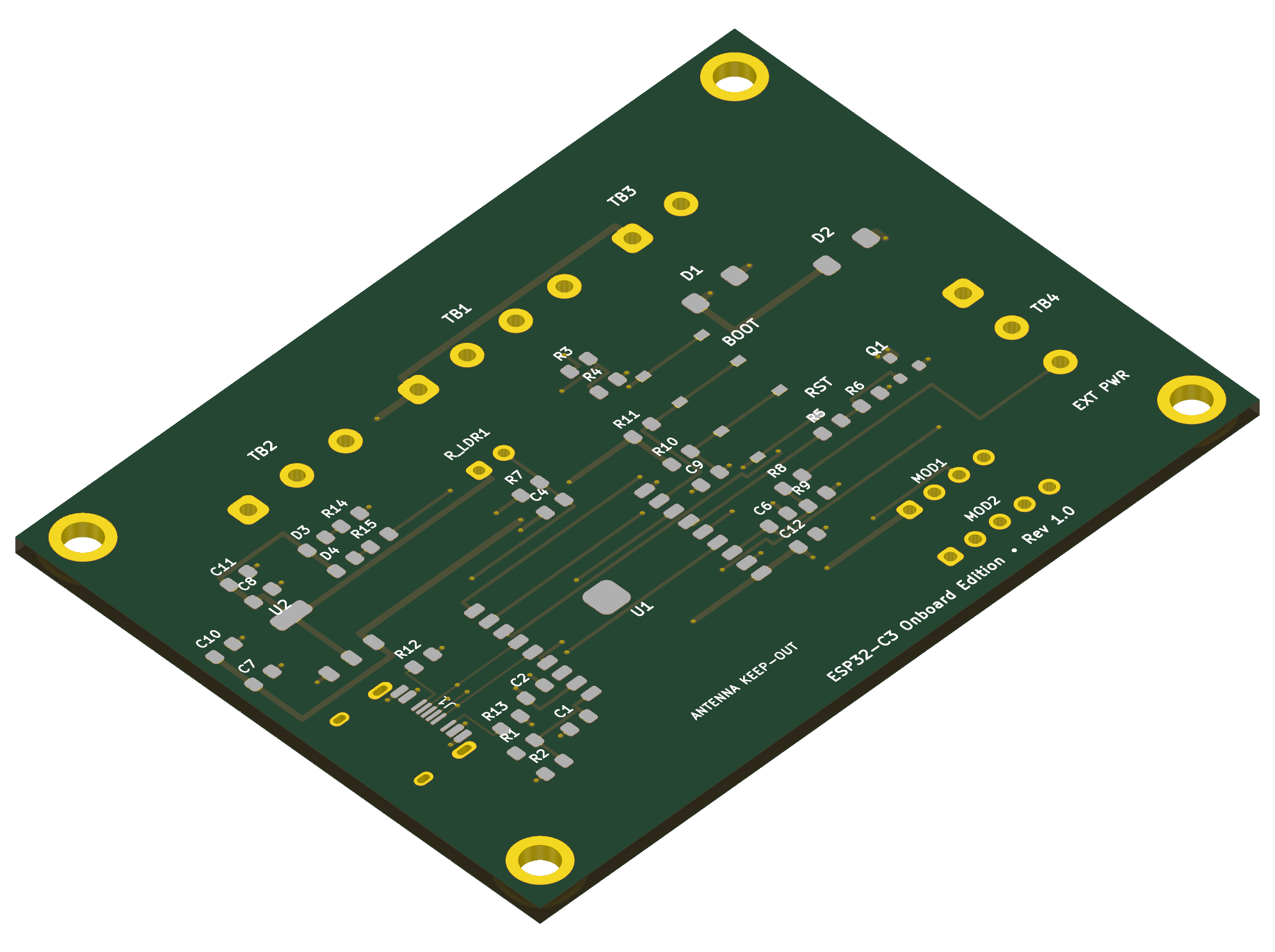
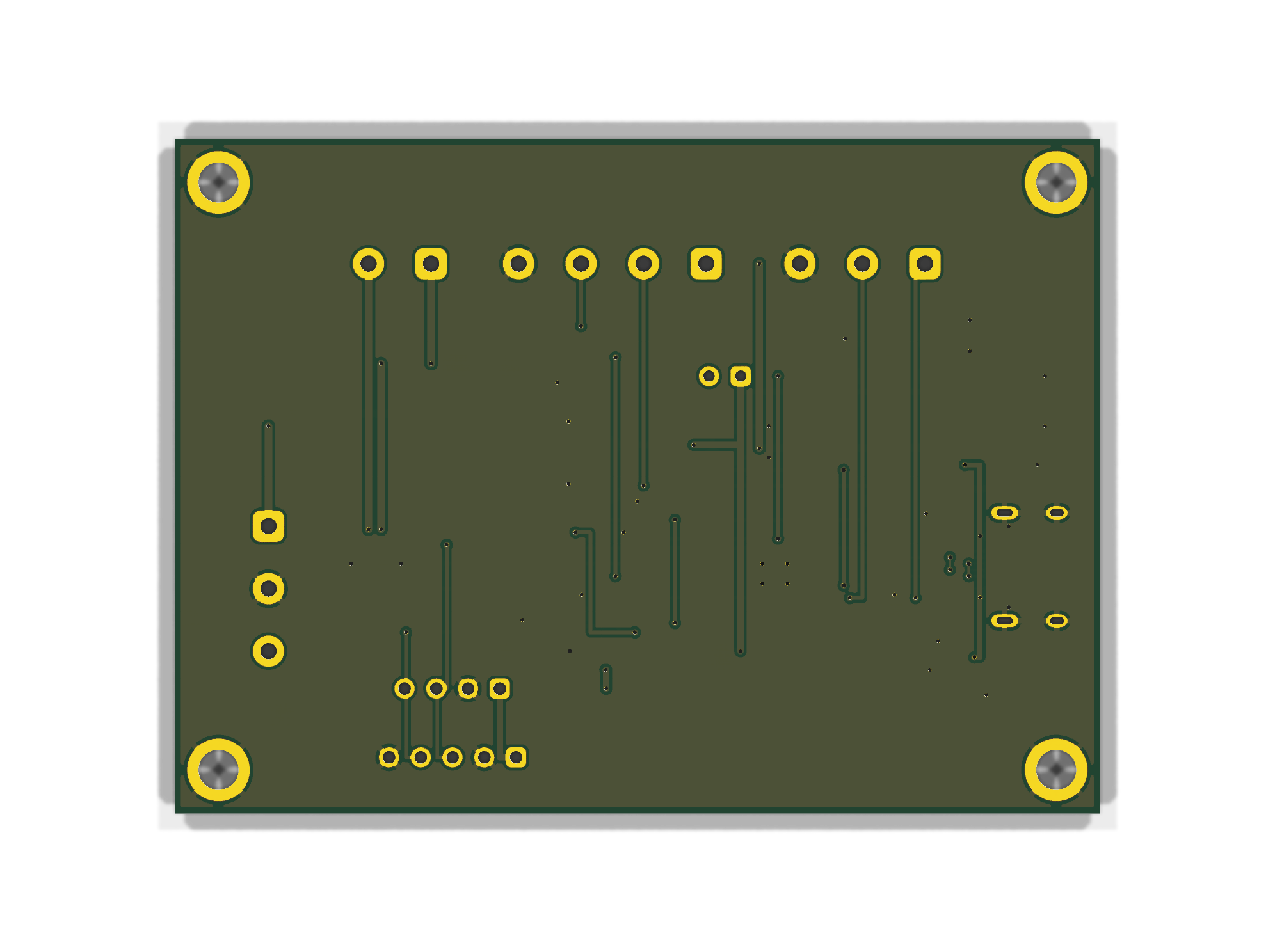
This directory contains the production files, Pick & Place centroid files (CPL), Bill of Materials (BOM), KiCad design source files, and 3D renders for the Monolithic Onboard SMD Edition of the Plant ESP32 watering…
Plant esp32-onboard is an open-source printed circuit board by thomaslr, from the thomaslr/plant-esp32 repository on GitHub. It is a 2-layer board of 74 × 54 mm with 46 parts on 27 nets, routed with 253 tracks and 65 vias.
It is built around the ESP32-C3-WROOM-02-H4, AMS1117-3.3 and SS34, with the AO3400A and TYPE-C 16PF among its other parts. Its parts include 15 resistors, 10 capacitors, 4 diodes, 2 ICs and 2 switches. It belongs with the ESP32 and RISC-V boards of this library.
This directory contains the production files, Pick & Place centroid files (CPL), Bill of Materials (BOM), KiCad design source files, and 3D renders for the Monolithic Onboard SMD Edition of the Plant ESP32 watering controller.
Rather than mounting an ESP32-C3 SuperMini daughterboard via pin headers, this turnkey edition integrates the official Espressif ESP32-C3-WROOM-02 Wi-Fi + BLE 5 module directly onto the PCB, complete with native USB-C, onboard AMS1117-3.3 power regulation, tactile RESET & BOOT buttons, status/power LEDs, and multi-stage filtering.
Optimized specifically for JLCPCB SMT Assembly using 100% Top-Side placement and prioritizing JLCPCB Basic Parts to keep assembly setup fees to an absolute minimum ($9.00 total for only 3 extended part reels across the entire production run).
Reversible 16-pin USB Type-C receptacle with dual 5.1 kΩ pulldown resistors (R12, R13) on CC1/CC2 for full USB-PD and C-to-C cable compliance.
Differential data pair (D+ / D-) routes directly to the ESP32-C3 hardware USB CDC/JTAG peripheral (GPIO 19 and GPIO 18), enabling direct flashing, bootloader entry, and serial monitoring without external USB-to-UART bridge ICs (no CP2102 or CH340 needed).
Dedicated Dual ADC Voltage Monitoring (Zero Jumpers):
18650 Battery Monitor (GPIO 4 / ADC1_CH4): Dedicated 100 kΩ / 100 kΩ divider (R8, R9) + 100 nF filter (C6). Directly measures raw 18650 Li-ion battery voltage ($3.0\text{V}\text{–}4.2\text{V}$) from TB4 Pin 3 (BAT). Quiescent drain is only 21 µA ($\sim 15\text{ mAh}$ per month), far below the battery's chemical self-discharge!
Both channels reside on ADC1, guaranteeing 100% reliable concurrent analog reads during active Wi-Fi streaming.
Dual Power Input Architecture with Anti-Backfeed Protection:
USB-C 5V Input: Powers the board and pump during development, desktop testing, or permanent indoor mains operation.
External Solar / Battery 5V Input (TB4-1): Connects to an external solar charge & boost module (e.g. DD05CVSA mini-UPS).
Anti-Backfeeding Schottky Diode (D2): 40V 3A SS34 Schottky diode (#C8678) placed in series between TB4-1 (EXT_5V) and the internal +5V rail. Blocks 100% of reverse current from backfeeding into the solar module when USB-C is plugged in.
Robust Power Regulation & Decoupling:
AMS1117-3.3 LDO (U2, SOT-223, Basic Part #C475931): Delivers up to 1000 mA of clean 3.3V logic power with wide copper tab heatsinking.
Multi-stage ceramic filtering: 10 µF (C10) + 100 nF (C7) at LDO input; 10 µF (C11) + 100 nF (C8) + 22 µF (C12) at LDO output directly adjacent to the ESP32 3V3 power pin.
Hardware Pushbuttons & Status Indicators:
RESET Button (SW1): Pulls EN to GND. Debounced by a 10 kΩ pull-up (R10) and 1 µF capacitor (C9).
BOOT Button (SW2): Pulls GPIO 9 to GND for manual ROM bootloader entry. Pulled high by 10 kΩ (R11).
PWR LED (D3, Green): Indicates 3.3V rail health.
STAT LED (D4, Blue): Active-low status indicator driven by GPIO 8 via 1 kΩ resistor (R15). Connected to +3.3V to ensure GPIO 8 is pulled HIGH during boot strapping.
RF Optimization & Antenna Keepout:
ESP32-C3-WROOM-02 inverted-F antenna points outward toward the bottom board edge.
Full copper keepout (no ground plane, no traces, no vias on top or bottom copper) under the antenna keepout zone.
Bill of Materials (BOM) & LCSC Part Mapping
SMT Assembly Parts (Factory Pre-Soldered by JLCPCB)
High-impedance 100k/100k voltage divider (R1, R2) + 100nF filter (C1)
GPIO 1
ADC1_CH1
Soil Moisture Data
Connects to TB2 Pin 1 with 100nF RF noise bypass (C2)
GPIO 3
ADC1_CH3
Ambient Light Sense
Voltage divider with LDR1 photoresistor and 10k resistor (R7) + 100nF filter (C4)
GPIO 4
ADC1_CH4
18650 Battery Sense
High-impedance 100k/100k voltage divider (R8, R9) from TB4 Pin 3 (21 µA drain)
GPIO 5
Digital Out
Soil Sensor VCC
Switched 3.3V power to TB2 Pin 2 (duty-cycled to prevent probe corrosion)
GPIO 6
Digital In
Ultrasonic Echo
Level-divided 3.3V pulse from TB1 Pin 3 via 1k/2k divider (R3, R4)
GPIO 7
Digital Out
Pump MOSFET Gate
Drives gate of AO3400A N-channel MOSFET (Q1) via 1k resistor (R5) & 100k pull-down (R6)
GPIO 8
Digital Out
Status LED
Drives Blue LED (D4) active-low via 1k resistor (R15) to +3.3V (boot strapping safe)
GPIO 9
Strapping Pin
BOOT Button
Pulled high to 3.3V by 10k resistor (R11); pressed to GND by tactile button SW2
GPIO 10
Digital Out
Ultrasonic Trig
Generates 10 µs trigger pulse to TB1 Pin 2
GPIO 18
USB_D-
USB Data Minus
Direct differential pair route to USB-C receptacle J1 Pin B7/A7
GPIO 19
USB_D+
USB Data Plus
Direct differential pair route to USB-C receptacle J1 Pin B6/A6
GPIO 20
U0RXD / I2C
I2C SDA
Hardware I2C Serial Data for MOD1 (SHT30) and MOD2 (BH1750)
GPIO 21
U0TXD / I2C
I2C SCL
Hardware I2C Serial Clock for MOD1 (SHT30) and MOD2 (BH1750)
EN
Chip Enable
Hardware Reset
Pulled high to 3.3V by 10k resistor (R10), 1µF debounce (C9), tactile button SW1 to GND
Flashing & Firmware Development
Native USB CDC/JTAG
The onboard ESP32-C3-WROOM-02 features a built-in USB Serial/JTAG controller connected directly to the USB-C port (GPIO 18 / GPIO 19). No driver installation is required on modern operating systems (macOS, Windows 10/11, Linux).
Upload Mode: USB-OTG CDC (TinyUSB) or Hardware CDC and JTAG
Port: Select the identified /dev/cu.usbmodem* (macOS) or COM* (Windows) device.
Entering ROM Bootloader Manually (If Required)
Under normal circumstances, the esptool software automatically toggles the ESP32-C3 into download mode via USB CDC control lines. If a bricked firmware prevents auto-reset:
Press and hold the BOOT button (SW2).
Press and release the RESET button (SW1).
Release the BOOT button (SW2).
The ESP32-C3 is now in ROM bootloader mode ready for flashing.
Analog Voltage Calculations
cpp
// 12-bit ADC with 3.3V full-scale reference (attenuation 11dB)// GPIO 0: 5V Rail Sense (100k / 100k divider -> ratio = 2.0)float read5VRail(){uint32_t raw = analogReadMilliVolts(0);
return(raw * 2.0f) / 1000.0f; // Volts}// GPIO 4: 18650 Battery Sense (100k / 100k divider -> ratio = 2.0)float readBatteryVoltage(){uint32_t raw = analogReadMilliVolts(4);
return(raw * 2.0f) / 1000.0f; // Volts (3.0V = 0%, 4.2V = 100%)}
Set dimensions: 74.0 mm × 54.0 mm, 2 layers, PCB thickness 1.6 mm, Solder mask Green, Silkscreen White, Surface finish HASL (with lead) or LeadFree HASL.
Enable PCB Assembly:
Switch the PCB Assembly toggle to ON.
Select Assemble top side only (Bottom side: No).
Tooling holes: Select Added by JLCPCB.
Upload BOM & CPL:
Upload plant-esp32-onboard_bom.csv to the Bill of Materials field.
Upload plant-esp32-onboard_cpl.csv to the Pick & Place / Centroid field.
Review Component Placement:
Verify all 0805 components, SOT-223 regulator, SMA diodes, USB-C receptacle, tactile buttons, and ESP32-C3 module align with their silkscreen footprints.
Note: The CPL file has been pre-rotated according to EIA-481 tape & reel packaging standards (AO3400A at 90.0°, ESP32-C3 at 180.0°, USB-C at 270.0°).
Checkout:
Complete payment and receive turnkey, pre-assembled boards!
This directory contains the production files, Pick & Place centroid files (CPL), Bill of Materials (BOM), KiCad design source files, and 3D renders for the Monolithic Onboard SMD Edition of the Plant ESP32 watering…
This directory contains the production files, Pick & Place centroid files (CPL), Bill of Materials (BOM), KiCad design source files, and 3D renders for the Monolithic Onboard SMD Edition of the Plant ESP32 watering…
12–24 V LED şeritleri WiFi üzerinden açıp kapatan ve PWM ile dimleyen küçük bir kontrol kartı. Proje KiCad donanım dosyalarını, iki firmware seçeneğini (ESPHome / PlatformIO) ve 3D yazıcıyla basılabilen bir kutuyu…
It measures 74 × 54 mm and has 2 copper layers, 1.6 mm thick.
What parts does the Plant esp32-onboard use?
46 parts, built around the ESP32-C3-WROOM-02-H4, AMS1117-3.3, SS34 and AO3400A. The full list of its parts is on this page, with links to each part's symbol and footprint where PCBKit's library has them.
Where can I download the Plant esp32-onboard KiCad files?
From the thomaslr/plant-esp32 repository on GitHub, at the commit this page was made from: the board is pcb/esp32-onboard-smd/plant-esp32-onboard.kicad_pcb and its schematic pcb/esp32-onboard-smd/plant-esp32-onboard.kicad_sch. PCBKit opens the board in the browser, with nothing to install.
Can I use the Plant esp32-onboard design in my own project?
Its repository states no licence, so its author keeps all rights: ask thomaslr before reusing the design.