2 layers101.5 × 64 mm
Nervous sys
NERVOUS-System-Project/SNN-Breadboard
KiCad schematic and PCB layout design of controller for Nervous-Systems
56 parts

 ThomasLindenberger37/MacropadMK
MacropadMK is a 12-key macropad built around the Waveshare ESP32-S3-Zero. The board combines a diode-isolated 4 × 3 keyboard matrix, three USB-C power-entry options, and two general-purpose JST-SH connections in a…
MacropadMK is an open-source printed circuit board by ThomasLindenberger37, from the ThomasLindenberger37/MacropadMK repository on GitHub, published under the MIT licence. It is a 2-layer board of 85.7 × 114.3 mm with 72 parts on 64 nets, routed with 392 tracks and 47 vias.
It is built around the 1N4148W, WS2812B and BPW85. Its parts include 20 resistors, 19 diodes, 12 switches, 7 connectors and 4 capacitors. It belongs with the keyboards and input boards of this library.


MacropadMK is a 12-key macropad built around the Waveshare ESP32-S3-Zero. The board combines a diode-isolated 4 × 3 keyboard matrix, three USB-C power-entry options, and two general-purpose JST-SH connections in a compact design.
The PCB is intended for an accessible prototyping workflow: order bare boards, assemble and validate the first units by hand, then reuse the same LCSC-aware bill of materials for a later JLCPCB assembly run.
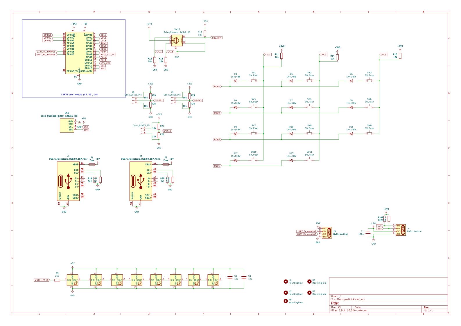
COL2ROWBOARD_5V, 3V3, and GNDThe switches form a 4-row by 3-column matrix. ROW1 through ROW4 are scanned
one at a time by driving the selected row low. COL1 through COL3 are inputs,
each held high by an external 10 kΩ pull-up resistor to 3V3.
Each key is an independent branch:
COLx -> switch -> diode anode -> diode cathode -> ROWxThe diode orientation is COL2ROW: the cathode, identified by the stripe on the
physical diode, points toward the row line. When a selected row is low and a key
on that row is pressed, its column input is pulled low through the switch and
diode.
| Signal group | Quantity | Scan role | External bias |
|---|---|---|---|
ROW1–ROW4 | 4 | Driven low individually | None |
COL1–COL3 | 3 | Digital inputs | 10 kΩ to 3V3 per column |
The ESP32-S3-Zero already has its own USB-C connector. The PCB provides two additional connector positions as alternative 5 V inputs:
TYPE-C-31-M-12MC-110LD-L124, USB 2.0, 16 pins, with THT mounting tabsC3039282The additional connectors are currently used only for power. They are still full USB 2.0 connector parts so that the same components and footprints can be reused in future designs with USB data support.
Each additional receptacle follows these connection rules:
CC1 to GND through its own 5.1 kΩ resistor.CC2 separately to GND through its own 5.1 kΩ resistor.D+, D-, SBU1, and SBU2 unconnected and mark them as no-connect.Each alternative receptacle feeds the common BOARD_5V rail through a separate
solder bridge. BOARD_5V connects to the ESP32-S3-Zero 5 V pin. An optional
resettable fuse rated for approximately 1 A can be fitted ahead of the shared
rail.
Place 10 µF bulk capacitance and 100 nF decoupling close to the 5 V input. Route VBUS with approximately 0.8–1.0 mm wide traces; 0.25 mm traces are not recommended for a 1 A supply path.
Power-source warning: The board does not provide input OR-ing or reverse- current isolation. Only one USB power source may be connected at a time unless suitable input decoupling and source isolation are added.
The board provides two identically pinned 3-position JST-SH connectors with a 1.0 mm pitch.
Connector_Generic:Conn_01x03Connector_JST:JST_SH_SM03B-SRSS-TB_1x03-1MP_P1.00mm_Horizontal| Pin | Signal |
|---|---|
| 1 | GND |
| 2 | 3V3 |
| 3 | Signal |
Components should use LCSC C part numbers wherever practical. The same part
numbers can be used both for loose component orders from LCSC and for JLCPCB
assembly BOM matching.
The intended manufacturing sequence is:
Download the schematic as PDF.
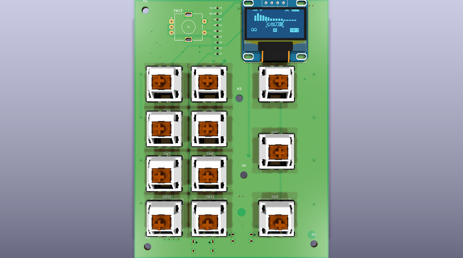
Some connector or encoder models may be absent from the rendered 3D preview if their STEP files are not available locally. This does not affect the Gerber or drill exports, but mechanical fit must still be checked before ordering.
The repository contains its KiBot automation directly under scripts/. Docker
is required; the scripts use the KiCad 10 KiBot image configured in
scripts/project.config.yaml.
Generate the schematic PDF/SVG and the 3D preview:
./scripts/assets.shGenerate Gerbers, drill files, BOM, placement data, the manufacturer ZIP, and STEP models:
./scripts/fabrication.shGenerated manufacturing files are written to Fabrication/. The validated
manufacturer archive is Fabrication/MacropadMK-Gerber_Pack.zip.
The relevant configuration files are:
scripts/project.config.yaml — project name, KiCad image, PCB thickness, and
mechanical-hole settingsscripts/kibot/config.kibot.yaml — manufacturing outputs and production
layersscripts/kibot/kibot_assets.kibot.yaml — documentation PDF, SVG, and 3D
render outputsAlways run KiCad ERC and DRC and review the generated Gerbers before submitting an order. Successful file generation does not imply that the electrical or mechanical design is production-ready.
The GitHub Actions fabrication workflow generates manufacturing artifacts when changes are pushed to the repository:

| Qty | Value | Footprint | References |
|---|---|---|---|
| 12 | 10k | Resistor_SMD:R_0603_1608Metric | R10, R11, R12, R13, R14, R15, R23, R24, R25, R26, R27, R28 |
| 11 | 1N4148W | Diode_SMD:D_SOD-123 | D3, D4, D5, D6, D7, D8, D9, D10, D11, D12, D13 |
| 11 | SW_Push | Keyswitch_Cherry_MX:SW_Cherry_MX_PCB_1.00u | SW1, SW2, SW3, SW4, SW5, SW6, SW7, SW8, SW9, SW10, SW11 |
| 8 | WS2812B | LED_SMD:LED_WS2812B_PLCC4_5.0x5.0mm_P3.2mm | D1, D2, D14, D15, D16, D17, D18, D19 |
| 5 | MountingHole | MountingHole:MountingHole_3.2mm_M3 | H1, H2, H3, H4, H5 |
| 4 | 5k1 | Resistor_SMD:R_0603_1608Metric | R18, R19, R20, R21 |
| 3 | 2k2 | Resistor_SMD:R_0603_1608Metric | R9, R16, R17 |
| 3 | Conn_01x03_Pin | Connector_JST:JST_SH_BM03B-SRSS-TB_1x03-1MP_P1.00mm_Vertical | J3, J6, J7 |
| 2 | 100n | Capacitor_SMD:C_0805_2012Metric | C1, C4 |
| 2 | 10u | Capacitor_SMD:C_0805_2012Metric | C2, C3 |
| 2 | Fuse | Fuse:Fuse_0805_2012Metric | F1, F2 |
| 2 | Qwiic_Vertical | Connector_JST:JST_SH_BM04B-SRSS-TB_1x04-1MP_P1.00mm_Vertical | J4, J5 |
| 1 | 100k | Resistor_SMD:R_0603_1608Metric | R29 |
| 1 | BPW85 | LED_SMD:LED_0603_1608Metric | Q1 |
| 1 | OLED_SSD1306_0.96in_128x64_I2C | SSD1306_OLED:OLED_SSD1306_0.96in_128x64_I2C | DS1 |
| 1 | RotaryEncoder_Switch_MP | Rotary_Encoder:RotaryEncoder_Alps_EC11E-Switch_Vertical_H20mm | SW13 |
| 1 | USB_C_Receptacle_USB2.0_16P_AXIAL | Connector_USB:USB_C_Receptacle_JAE_DX07S024WJ3R400 | J2 |
| 1 | USB_C_Receptacle_USB2.0_16P_FLAT | Connector_USB:USB_C_Receptacle_HRO_TYPE-C-31-M-12 | J1 |
| 1 | ~ | MacropadMK_Custom_Footprints:ESP32-S3-Zero | U1 |
NERVOUS-System-Project/SNN-Breadboard
KiCad schematic and PCB layout design of controller for Nervous-Systems

fossasia/pslab-hardware
PSLab Hardware Design and Schematics https://pslab.io


ozkan/Cockpit-Keyboard
A hot swap system column staggered mechanical keyboard, running QMK Firmware on Pro Micro controllers.

ozkan/skywatch
35% ergonomic ortholinear keyboard, powered by RP2040, along with OLED and hotswap sockets support

NuttyShell/NuttyBadge
NuttyBadge: A NuttyShell crafted multi-tool. Opensourced Hardawre and Software

sadekbaroudi/euclid36
At the time of creation, using Kicad 5.1.9 - This may not work with future versions

It measures 85.7 × 114.3 mm and has 2 copper layers, 1.6 mm thick.
72 parts, built around the 1N4148W, WS2812B and BPW85. The full list of its parts is on this page, with links to each part's symbol and footprint where PCBKit's library has them.
From the ThomasLindenberger37/MacropadMK repository on GitHub, at the commit this page was made from: the board is MacropadMK.kicad_pcb and its schematic MacropadMK.kicad_sch. PCBKit opens the board in the browser, with nothing to install.
Its repository publishes it under the MIT licence: you may reuse it on that licence's terms (keep the author's notice, and for a copyleft licence share your changes alike).