2 layers80 × 46 mm
Main control board
StarweaverAudioLabs/main_control_board
Main controller board for Haruto's DAC
51 partsGPL-3.0

 thatoddmailbox/kvm-base19
The main board for the open-source HDMI KVM switch I built.
Kvm base is an open-source printed circuit board by thatoddmailbox, from the thatoddmailbox/kvm-base repository on GitHub. It is a 4-layer board with 70 parts on 162 nets, routed with 4,940 tracks and 93 vias.
It is built around the STM8S003F3P6, TMDS361BPAG and SL2.1A, with the AMS1117-3.3 and FSUSB74UMX among its other parts. Its parts include 29 capacitors, 16 connectors, 12 resistors, 6 ICs and 1 switch. It belongs with the interfaces and adapters boards and the STM8 boards of this library.


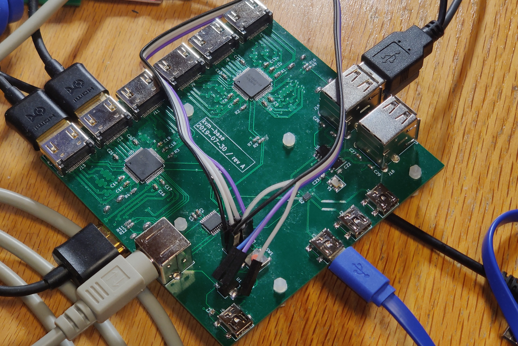
The main board for the open-source HDMI KVM switch I built. Contains HDMI and USB switch ICs, allowing you to share two monitors and four USB devices between three different computers.
This is a 1.6mm four layer PCB, designed for JLCPCB's JLC7628 impedance-controlled stackup. It most likely will not work (or will be limited in terms of HDMI performance) on another stackup.
It connects via a PS/2 cable to kvm-keypad—however, it does not use the actual PS/2 protocol.
Two TMDS361B chips are used as HDMI switches, and an FSUSB74 is used as the USB switch.
The full Bill of Materials is linked at the end of the README, and you should get the PCB fabricated at JLCPCB with their impedance-controlled JLC7628 process.
A stencil is probably the easiest way to assemble the board, but it's definitely possible to do so without one, as long as you have a hot air rework station. The trickiest parts to solder are probably the FSUSB74 (QFN with 0.4 mm pitch but no thermal pad) and the TMDS361B (TQFP with 0.5 mm pitch).
The HDMI connectors are also somewhat tricky, given that they are on both sides of the board and also have a relatively fine pitch. However, it's doable with a soldering iron, flux, solder wick, and ideally some form of magnification—you just have to be careful to ensure the pins are aligned with the footprint on the board before soldering.
Interestingly, the TMDS361B's datasheet pretty clearly states that it's "not intended for source side applications such as external switch boxes", which I probably missed when designing this board.
The consequences of this seem to be that there's little/no ESD protection on the sink side (the monitor output ports), and that the chip has a fairly weak sink-side output stage. That means you probably can't use the output with super long or super cheap cables. The inputs, however, should be fine, since TI claims that the TMDS361B has a "robust TMDS receive stage" that even works with out-of-spec HDMI signals.
Anecdotally, the output does seem to work, but I haven't tested it in that many conditions. This has been tested with a 3 foot HDMI cable going to an Acer EB243YU monitor, using a resolution of 2560 x 1440 at 75 Hz, which is outside of the TMDS361B's spec!
Theoretically, you might be able to work around this by running the output signals to another board with a retimer or redriver, but that's probably somewhat excessive. A future revision should use a different chip and/or integrate a retimer/redriver to the output stage. Unfortunately, it might be somewhat tricky to find an easily accessible HDMI switch chip—most seem to want you to sign an NDA before getting any documentation.
xrandr --listmonitors.| Qty | Value | Footprint | References |
|---|---|---|---|
| 10 | 0.1uF | Capacitor_SMD:C_0603_1608Metric_Pad1.05x0.95mm_HandSolder | C3, C5, C8, C9, C12, C13, C16, C17, C20, C21 |
| 8 | 10uF | Capacitor_SMD:C_0603_1608Metric_Pad1.05x0.95mm_HandSolder | C1, C2, C24, C25, C26, C27, C28, C29 |
| 8 | 1uF | Capacitor_SMD:C_0603_1608Metric_Pad1.05x0.95mm_HandSolder | C6, C7, C10, C11, C14, C15, C18, C19 |
| 8 | HDMI_A | kvm-base:HDMI-001 | J7, J8, J9, J10, J11, J12, J13, J14 |
| 6 | 10k | Resistor_SMD:R_0603_1608Metric_Pad1.05x0.95mm_HandSolder | R1, R3, R5, R6, R7, R8 |
| 4 | 5.9k | Resistor_SMD:R_0603_1608Metric_Pad1.05x0.95mm_HandSolder | R9, R10, R11, R12 |
| 4 | USB_B_Mini | Connector_USB:USB_Mini-B_Lumberg_2486_01_Horizontal | J1, J2, J3, J4 |
| 2 | 12pF | Capacitor_SMD:C_0603_1608Metric_Pad1.05x0.95mm_HandSolder | C22, C23 |
| 2 | 4.02k | Resistor_SMD:R_0603_1608Metric_Pad1.05x0.95mm_HandSolder | R2, R4 |
| 2 | TMDS361B | Package_QFP:LQFP-64_10x10mm_P0.5mm | U4, U5 |
| 2 | USB_Dual_A | Connector_USB:USB_A_Wuerth_61400826021_Horizontal_Stacked | J15, J16 |
| 1 | 0.47uF | Capacitor_SMD:C_0603_1608Metric_Pad1.05x0.95mm_HandSolder | C4 |
| 1 | 12MHz | Crystal:Crystal_SMD_3225-4Pin_3.2x2.5mm_HandSoldering | Y1 |
| 1 | AMS1117-3.3 | Package_TO_SOT_SMD:SOT-223-3_TabPin2 | U1 |
| 1 | Debug | Connector_PinSocket_2.54mm:PinSocket_2x04_P2.54mm_Vertical | J6 |
| 1 | FSUSB74 | kvm-base:UMLP16 | U2 |
| 1 | Keypad | kvm-base:PS2 | J5 |
| 1 | Reset | Button_Switch_SMD:SW_Push_1P1T_NO_6x6mm_H9.5mm | SW1 |
| 1 | SL2.1A | Package_SO:SOIC-16_3.9x9.9mm_P1.27mm | U6 |
| 1 | STM8S003F3P | Package_SO:TSSOP-20_4.4x6.5mm_P0.65mm | U3 |
The 65 most common of 70 parts.
70 parts, built around the STM8S003F3P6, TMDS361BPAG, SL2.1A and AMS1117-3.3. The full list of its parts is on this page, with links to each part's symbol and footprint where PCBKit's library has them.
From the thatoddmailbox/kvm-base repository on GitHub, at the commit this page was made from: the board is kvm-base.kicad_pcb. PCBKit opens the board in the browser, with nothing to install.
Its repository states no licence, so its author keeps all rights: ask thatoddmailbox before reusing the design.
StarweaverAudioLabs/main_control_board
Main controller board for Haruto's DAC

dilshan/ir-clone
Open-source infrared remote control signal analysis and generating tool


akuker/SuperUPS
This is a fork of the original Supercapacitor UPS board for a Raspberry Pi by Scott Baker, http://www.smbaker.com/


TLDR-Electronics/STM8S003F3_PCB_Breakout_and_C_examples
STM8S003F3 Breakout board and Simple STM8 C examples with the SDCC compiler

Amir-imani/Autonomous-Mobile-Robot
Thesis project: Design and Construction of a Mobile Robot with Intelligent Path Planning in Dynamic Environments.

maupassant9/TemperatureControllerForOven
Temperature Controller for oven with ESP8266