
2 layers27.4 × 58.7 mm
Lc29h mikrobus PCB
i2hm/micro_climate_station
Open the KiCad project using KiCad 7 and above.
48 parts3

Four-channel Raspberry Pi HAT for gLOWCOST scintillator/MPPC readout with programmable bias, thresholds, and FPGA hit processing.
RPi Hat is an open-source printed circuit board by tharinduudu, from the tharinduudu/gLOWCOST-2v2-mppcInterface- repository on GitHub. It is a 6-layer board of 65 × 56.5 mm with 204 parts on 131 nets, routed with 892 tracks and 155 vias.
It is built around the ICE40LP384-SG32TR, MEA1D0505SC and OPA846ID, with the MAX1932ETC+, TLV3603DCKR and MIC5504-1.2YM5-TR among its other parts. Its parts include 88 capacitors, 69 resistors, 15 ICs, 10 inductors and 6 connectors. It belongs with the fPGA and programmable logic boards and the FPGA and CPLD boards of this library.


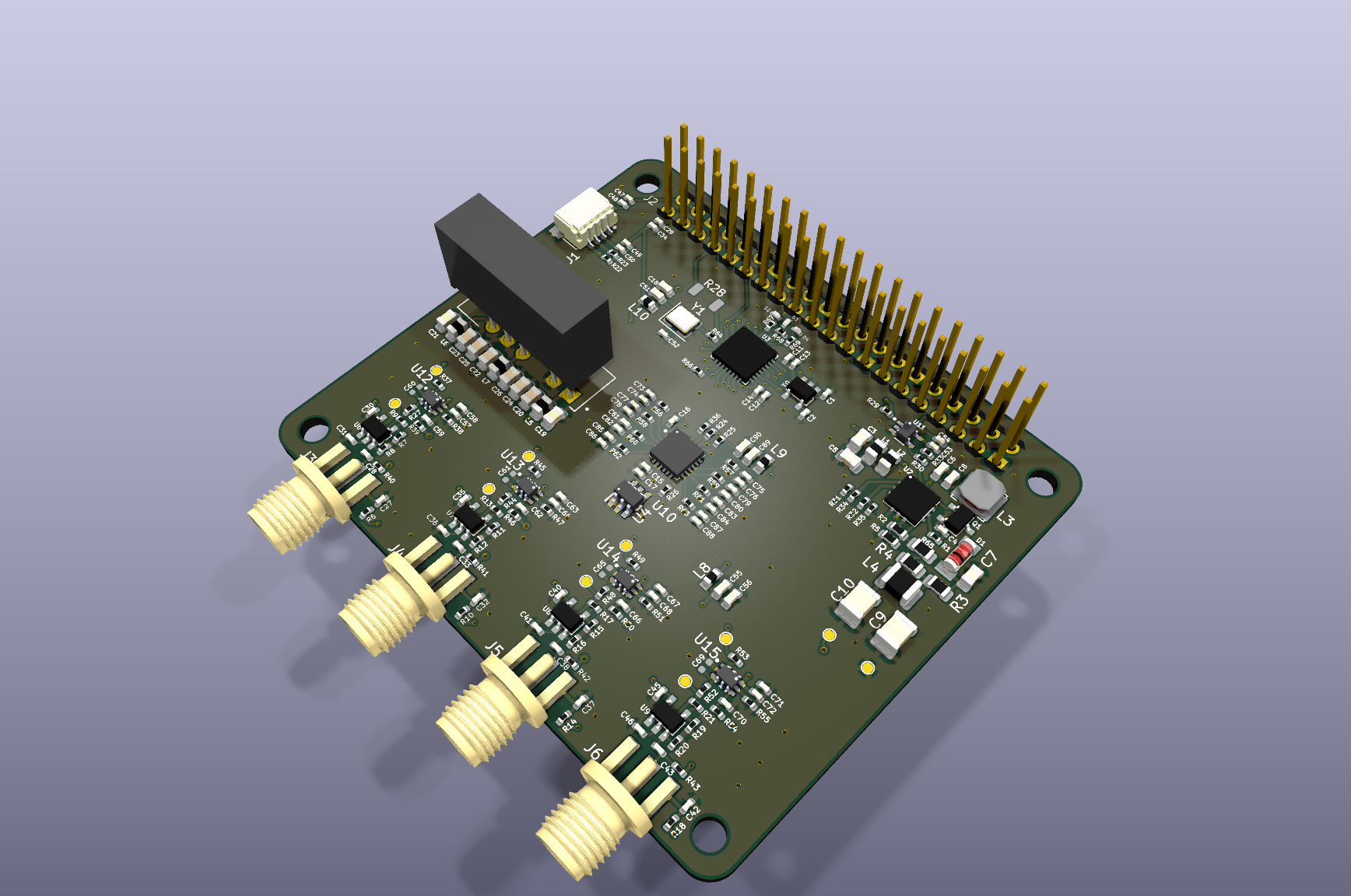
gLOWCOST 2v2 is a six-layer Raspberry Pi HAT for MPPC readout, bias control, and fast comparator interfacing. The design combines four sensor-interface channels with programmable bias/control, high-speed analog signal conditioning, FPGA logic, and the Raspberry Pi 40-pin interface.
This repository contains a documented release of the working, hardware-tested KiCad design. The electrical topology, copper routing, footprints, board outline, and stack-up from the tested source have been preserved. Repository hygiene, project portability, release automation, title blocks, and board identification have been added around that validated design.
A charged particle crossing an external scintillator produces light that reaches an MPPC/SiPM. The board applies the sensor bias, AC-couples and amplifies the resulting fast pulse, compares it with a programmable per-channel threshold, and sends a digital hit to the FPGA. The deployed FPGA/Pi software can count individual hits and multi-layer coincidences, which reject much of the uncorrelated SiPM dark-count background.
The PCB provides four complete channels. DAC0-DAC3 trim the four sensor operating points, while DAC4-DAC7 set the four comparator thresholds. The scintillators, MPPCs, FPGA bitstream, Raspberry Pi acquisition software, and external environmental sensor are separate parts of the complete detector and are not stored in this hardware repository.
See Detector functionality for the complete signal path, channel map, bias and threshold calibration, deployed coincidence behavior, temperature compensation, and the boundary between PCB-defined and firmware-defined functions.
High-voltage warning: the four SMA connector shells are assigned to
HV_out, not ground. Read the safety and measurement guidance before connecting sensors or grounded test equipment.
THARINDU identification is retained on the bottom silkscreen. This is non-electrical.Install KiCad 9 or later, clone the repository, and open RPi_Hat.kicad_pro. The checked-in sym-lib-table and fp-lib-table resolve the bundled project libraries through ${KIPRJMOD}, so no machine-specific paths are required.
git clone https://github.com/tharinduudu/gLOWCOST-2v2-mppcInterface-.git
cd gLOWCOST-2v2-mppcInterface-
open RPi_Hat.kicad_proRun the repeatable KiCad checks, including project-local 3D-model coverage:
./scripts/check.shCreate Gerbers, drill files, pick-and-place data, BOM, schematic/assembly PDFs, STEP, checksums, and a release ZIP:
./scripts/build_release.shGenerated working files go under build/ and are intentionally ignored. The reviewed manufacturing package is published under manufacturing/rev2.2/, with a ready-to-download archive at manufacturing/gLOWCOST-2v2-rev2.2.zip.
The board is reported as built and tested. KiCad still reports inherited review findings in the preserved source. They are captured in docs/DESIGN_REVIEW.md and machine-readable reports under docs/validation/; the validation script guards against increases beyond that reviewed baseline. The 3D coverage and model provenance are documented in docs/3D_MODELS.md.
Before ordering another fabrication run, review docs/MANUFACTURING.md, confirm the stack-up and surface finish with the fabricator, and compare the generated package against the previously qualified order.
| Path | Purpose |
|---|---|
RPi_Hat.kicad_pro | Main KiCad project |
RPi_Hat.kicad_sch | Main schematic |
RPi_GPIO.kicad_sch | Raspberry Pi GPIO child sheet |
RPi_Hat.kicad_pcb | Six-layer PCB layout |
components/ | Project-local symbols, footprints, models, and datasheets |
bom/source/ | Original procurement BOM supplied with the tested design |
docs/ | Detector functionality, design review, and manufacturing documentation |
manufacturing/rev2.2/ | Reviewed fabrication and assembly outputs |
manufacturing/gLOWCOST-2v2-rev2.2.zip | Downloadable revision 2.2 manufacturing package |
scripts/ | Repeatable validation and release generation |
This is hardware. Treat any change to connectivity, routing, footprints, stack-up, clearances, or manufacturing outputs as a new hardware revision requiring review and requalification. See CONTRIBUTING.md.
| Qty | Value | Footprint | References |
|---|---|---|---|
| 21 | 0u1 | passives:C-0402 | C11, C12, C14, C15, C16, C27, C29, C30, C31, C32, C35, C36, C37, C40, C41, C42 +5 |
| 17 | 100n | passives:C-0402 | C52, C58, C59, C62, C63, C66, C67, C70, C71, C74, C76, C78, C80, C82, C84, C86 +1 |
| 15 | 1K | passives:R-0402 | R6, R10, R14, R18, R39, R40, R41, R42, R43, R46, R50, R54, R67, R68, R69 |
| 13 | 22 | passives:R-0402 | R37, R45, R49, R53, R56, R57, R58, R59, R60, R61, R62, R63, R64 |
| 12 | 1u | passives:C-0402 | C1, C2, C13, C17, C28, C33, C34, C38, C43, C48, C50, C54 |
| 11 | 10K | passives:R-0402 | R22, R23, R24, R25, R26, R29, R33, R34, R35, R36, R66 |
| 8 | 49R9 | passives:R-0402 | R7, R8, R11, R12, R15, R16, R19, R20 |
| 8 | 4u7 | passives:C-0402 | C73, C75, C77, C79, C81, C83, C85, C87 |
| 7 | 1u | passives:C-0805 | C3, C5, C20, C23, C24, C25, C26 |
| 4 | 150K | passives:R-0402 | R38, R47, R51, R55 |
| 4 | 1n | passives:C-0402 | C57, C64, C68, C72 |
| 4 | 1p | passives:C-0402 | C60, C61, C65, C69 |
| 4 | 200 | passives:R-0402 | R27, R44, R48, R52 |
| 4 | 4.9K | passives:R-0402 | R9, R13, R17, R21 |
| 4 | CONSMA003.062-G | BWSMA-KE-P001:BATWIRELESS_BWSMA-KE-P001 | J3, J4, J5, J6 |
| 4 | OPA846 | OPA84X:SOT-23-5 | U6, U7, U8, U9 |
| 4 | TLV3603DCKR | TLV3603DCKR:SOT65P210X110-6N | U12, U13, U14, U15 |
| 3 | 100n | passives:C-0603 | C51, C56, C90 |
| 3 | 10u | passives:L-0805 | L5, L6, L7 |
| 3 | 4u7 | passives:C-0805 | C19, C21, C22 |
| 3 | BL-HUB37A-AV-TRB | BL-HUB37A-AV-TRB:D-0402 | D2, D3, D4 |
| 3 | BLM18PG121SN1D | BLM18PG121SN1D:IND_BLM18_0603_MUR | L8, L9, L10 |
| 2 | 1u | passives:C-0603 | C6, C18 |
| 2 | 1u | passives:C-1210 | C9, C10 |
| 2 | 47R | passives:R-0402 | R31, R32 |
| 2 | 47u | passives:C-0603 | C55, C89 |
| 2 | 47u | passives:L-0805 | L1, L2 |
| 2 | 49.9k | passives:R-0805 | R4, R65 |
| 1 | 0 | passives:R-1206 | R28 |
| 1 | 0u1 | passives:C-0603 | C8 |
| 1 | 0u22 | passives:C-0402 | C4 |
| 1 | 150uH | SRN4018:SRN4018 | L3 |
| 1 | 1mH | passives:L-1210 | L4 |
| 1 | 20k | passives:R-0402 | R1 |
| 1 | 2K37 | passives:R-0603 | R5 |
| 1 | 2K49 | passives:R-0603 | R2 |
| 1 | 47n | passives:C-0805 | C7 |
| 1 | 68R | passives:R-0402 | R30 |
| 1 | 806R | passives:R-0805 | R3 |
| 1 | BSS123L | BSS123L:SOT-23-3 | Q1 |
| 1 | CH0 | tooling:TestPoint_Pad_D1.0mm | TP6 |
| 1 | CH1 | tooling:TestPoint_Pad_D1.0mm | TP7 |
| 1 | CH2 | tooling:TestPoint_Pad_D1.0mm | TP8 |
| 1 | CH3 | tooling:TestPoint_Pad_D1.0mm | TP9 |
| 1 | DAC6578xRGE | DAC6578SRGET:DAC6578SRGET | U10 |
| 1 | D_CH0 | tooling:TestPoint_Pad_D1.0mm | D_CH0 |
| 1 | D_CH1 | tooling:TestPoint_Pad_D1.0mm | D_CH1 |
| 1 | D_CH2 | tooling:TestPoint_Pad_D1.0mm | D_CH2 |
| 1 | D_CH3 | tooling:TestPoint_Pad_D1.0mm | D_CH3 |
| 1 | GND | tooling:TestPoint_Pad_D1.0mm | TP1 |
| 1 | HV | tooling:TestPoint_Pad_D1.0mm | TP2 |
| 1 | ICE40-LP384-SG32 | ICE40-LP384:ICE40-LP384-QFN32 | U3 |
| 1 | LL4148 | LL4148:SOD-80 | D1 |
| 1 | MAX1932 | MAX1932:TQFN-12 | U2 |
| 1 | MEA1D0505SC | CONV_MEA1D0505SC:CONV_MEA1D0505SC | U5 |
| 1 | MIC5504-1.2YM5 | MIC550X:SOT-23-5 | U1 |
| 1 | REF3430IDBVR | REF3430IDBVR:SOT95P280X145-6N | U4 |
| 1 | RPi_GPIO | RPI_Hat:RPI_Hat_B+ | J2 |
| 1 | SG-2032CAN | Crystal:Crystal_SMD_3225-4Pin_3.2x2.5mm | Y1 |
| 1 | SM04B-SRSS-TB_LF__SN_ | JST_SM04B-SRSS-TB_LF__SN_:JST_SM04B-SRSS-TB_LF__SN_ | J1 |
| 1 | SN74LVC1G08DCKR | SN74LVC1G08DCKR:SOT65P210X110-5N | U11 |
i2hm/micro_climate_station
Open the KiCad project using KiCad 7 and above.

jhns-de/70MHz-Soil-Sensor
Soil moisture and electrical conductivity (EC) sensor based on 70 MHz impedance measurement, developed as part of my master’s thesis.


NerdyProjects/conti_bat_trigger
Die Conti-Akkus aus dem Finger-Forum liegen immer noch rum, eine Platine muss her, damit es einfach wird.


MitkoDyakov/Calipatron
I design my own digital caliper based on STM32F103C8T6 blue pill.

CosmicPi/CosmicPiV1.7PCB
PCB for Version 1.7 of the Cosmic Pi Hardware. Incremental changes from V1.6. This design is licensed under the CERN OHL V1.2
It measures 65 × 56.5 mm and has 6 copper layers, 1.6 mm thick.
204 parts, built around the ICE40LP384-SG32TR, MEA1D0505SC, OPA846ID and MAX1932ETC+. The full list of its parts is on this page, with links to each part's symbol and footprint where PCBKit's library has them.
From the tharinduudu/gLOWCOST-2v2-mppcInterface- repository on GitHub, at the commit this page was made from: the board is RPi_Hat.kicad_pcb and its schematic RPi_GPIO.kicad_sch. PCBKit opens the board in the browser, with nothing to install.
Its repository states no licence, so its author keeps all rights: ask tharinduudu before reusing the design.