4 layers80.1 × 22.2 mm
M2-smart iot module
antmicro/m2-smart-iot-module
https://antmicro.com/blog/2021/08/open-hardware-smart-m2-radio-module-for-iot/
212 parts30Apache-2.0

 jhns-de/70MHz-Soil-Sensor2
Soil moisture and electrical conductivity (EC) sensor based on 70 MHz impedance measurement, developed as part of my master’s thesis.
70MHz Soil Sensor is an open-source printed circuit board by jhns-de, from the jhns-de/70MHz-Soil-Sensor repository on GitHub. It is a 4-layer board of 49 × 80 mm with 130 parts on 90 nets, routed with 547 tracks and 200 vias.
It is built around the ADA4857-1YRZ-R7, AD8691AKSZ-REEL7 and BL652-SA-01-T/R, with the ADS1115IDGSR, SN74LXC1T14DCK and TLV3603DCKR among its other parts. Its parts include 46 capacitors, 28 resistors, 15 ICs, 9 connectors and 7 diodes. It belongs with the sensors and measurement boards of this library.


Soil moisture and electrical conductivity (EC) sensor based on 70 MHz impedance measurement, initially developed as part of my master's thesis.
At 70 MHz, the ionic charge transport in soil is much slower than the dipole rotation of water molecules. This frequency therefore allows a clearer separation between the conductive and dielectric components of the soil response, improving the accuracy of both EC and volumetric water content (VWC) estimation.
The analog sensor determines the complex impedance of the soil using an analog front end that measures both the voltage across and the current through the soil probe. The circuit is optimised for low noise, high linearity, and phase accuracy at radio frequencies.
The sensor hardware was designed in KiCad as a compact four-layer FR-4 PCB.
Main components and design decisions:
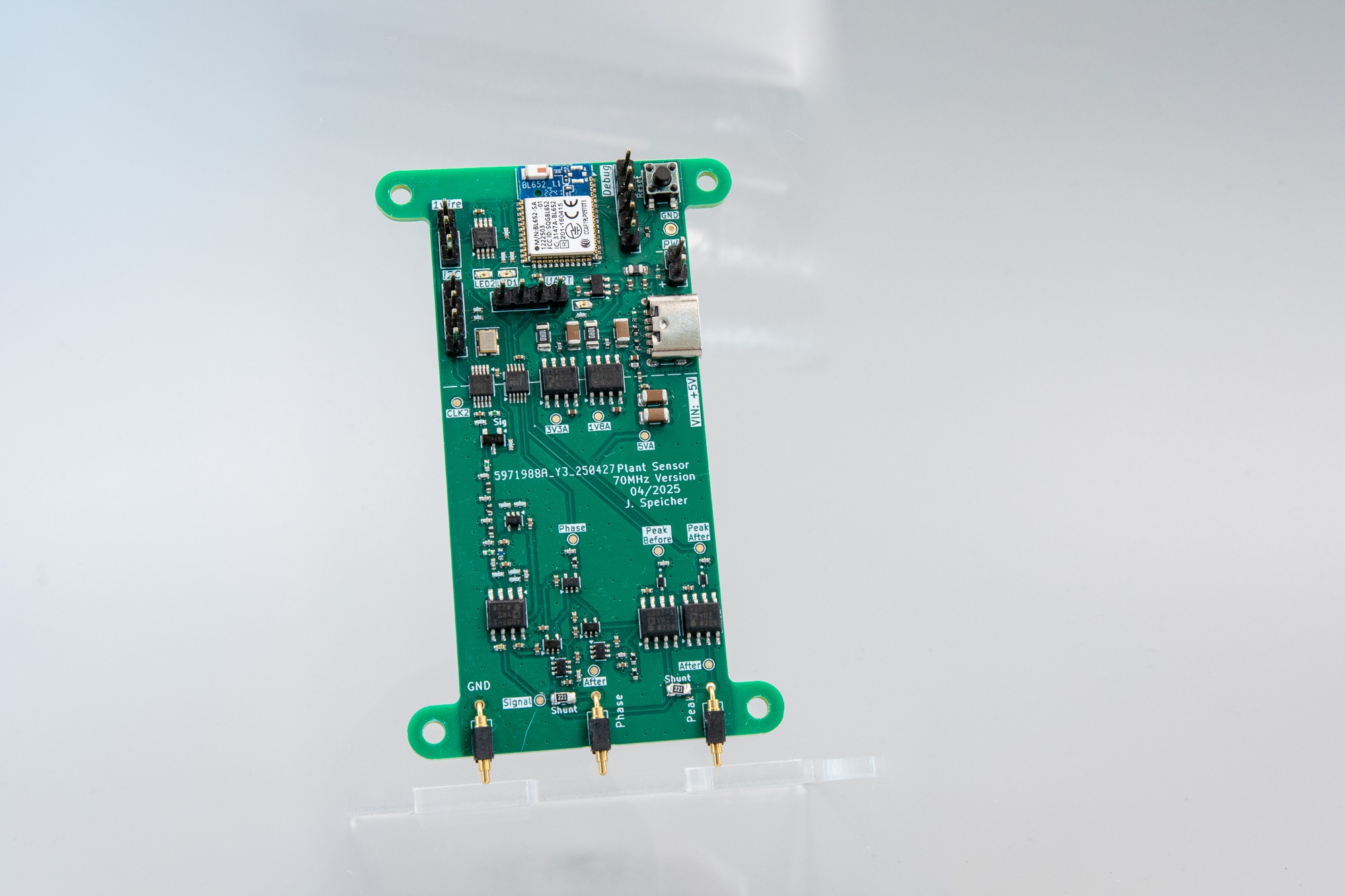
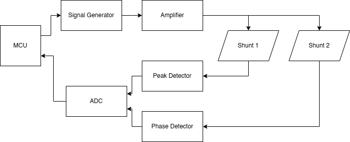
Detailed explanations of the measurement principle, calibration, and circuit design are available in the documentation directory.
All hardware design files (schematics, PCB layouts, and mechanical parts) are licensed under CERN-OHL-W-2.0, while all firmware and software components are released under the MIT License; both license texts are available in the LICENSE/ directory.
| Qty | Value | Footprint | References |
|---|---|---|---|
| 19 | 100n | Capacitor_SMD:C_0402_1005Metric | C101, C102, C103, C201, C202, C211, C212, C301, C302, C303, C304, C305, C306, C307, C308, C311 +3 |
| 10 | 1k | Resistor_SMD:R_0402_1005Metric | R107, R108, R201, R204, R206, R208, R209, R211, R212, R501 |
| 10 | TestPoint | TestPoint:TestPoint_Pad_D1.0mm | TP101, TP102, TP103, TP104, TP105, TP106, TP201, TP502, TP503, TP504 |
| 6 | 1u | Capacitor_SMD:C_0402_1005Metric | C207, C208, C501, C502, C503, C504 |
| 5 | 100p | Capacitor_SMD:C_0402_1005Metric | C309, C310, C312, C403, C404 |
| 4 | 47u | Capacitor_SMD:C_1206_3216Metric | C505, C508, C514, C515 |
| 4 | MountingHole | MountingHole:MountingHole_2.7mm_M2.5 | H101, H102, H103, H104 |
| 3 | 10k | Resistor_SMD:R_0402_1005Metric | R102, R301, R303 |
| 3 | 2u2 | Capacitor_SMD:C_0402_1005Metric | C506, C509, C511 |
| 3 | 4k7 | Resistor_SMD:R_0402_1005Metric | R101, R105, R106 |
| 3 | 50R | Resistor_SMD:R_0402_1005Metric | R202, R203, R205 |
| 3 | 829-22-001-20-001101 | custom:8292200120001101 | J104, J105, J106 |
| 3 | ADA4857-1 | Package_SO:SOIC-8_3.9x4.9mm_P1.27mm | U201, U401, U402 |
| 3 | LED | LED_SMD:LED_0603_1608Metric | D101, D102, D501 |
| 2 | 10R | Resistor_SMD:R_1206_3216Metric | R502, R505 |
| 2 | 10p | Capacitor_SMD:C_0402_1005Metric | C203, C209 |
| 2 | 160n | Inductor_SMD:L_0402_1005Metric | L201, L203 |
| 2 | 1n | Capacitor_SMD:C_0402_1005Metric | C507, C510 |
| 2 | 56p | Capacitor_SMD:C_0402_1005Metric | C204, C210 |
| 2 | 5k1 | Resistor_SMD:R_0402_1005Metric | R503, R504 |
| 2 | 8231706A | Diode_SMD:D_0402_1005Metric | D502, D503 |
| 2 | 91p | Capacitor_SMD:C_0402_1005Metric | C205, C206 |
| 2 | I2C | Connector_PinHeader_2.54mm:PinHeader_1x04_P2.54mm_Vertical | J103, J107 |
| 2 | SMS7621-079LF | custom:SODFL1608X70N | D401, D402 |
| 2 | SN74LXC1T14 | Package_TO_SOT_SMD:SOT-353_SC-70-5 | U302, U305 |
| 2 | TLV3603 | Package_TO_SOT_SMD:SOT-363_SC-70-6 | U301, U304 |
| 1 | 100k | Resistor_SMD:R_0402_1005Metric | R207 |
| 1 | 10n | Capacitor_SMD:C_0402_1005Metric | C512 |
| 1 | 16k | Resistor_SMD:R_0402_1005Metric | R302 |
| 1 | 180n | Inductor_SMD:L_0402_1005Metric | L202 |
| 1 | 1R | Resistor_SMD:R_0402_1005Metric | R210 |
| 1 | 1k | Resistor_SMD:R_0805_2012Metric_Pad1.20x1.40mm_HandSolder | R104 |
| 1 | 1wire | Connector_PinHeader_2.54mm:PinHeader_1x03_P2.54mm_Vertical | J101 |
| 1 | 22n | Inductor_SMD:L_0805_2012Metric_Pad1.05x1.20mm_HandSolder | L501 |
| 1 | 2k2 | Resistor_SMD:R_0805_2012Metric_Pad1.20x1.40mm_HandSolder | R103 |
| 1 | 470R | Inductor_SMD:L_0402_1005Metric | FB501 |
| 1 | 74AUC1G86 | Package_TO_SOT_SMD:SOT-353_SC-70-5 | U303 |
| 1 | 7M-27.000MEEQ-T | Crystal:Crystal_SMD_TXC_7M-4Pin_3.2x2.5mm | Y201 |
| 1 | AD8691 | Package_TO_SOT_SMD:SOT-353_SC-70-5 | U202 |
| 1 | ADP7142ARDZ-1.8 | Package_SO:SOIC-8-1EP_3.9x4.9mm_P1.27mm_EP2.29x3mm | U502 |
| 1 | ADP7142ARDZ-3.3 | Package_SO:SOIC-8-1EP_3.9x4.9mm_P1.27mm_EP2.29x3mm | U503 |
| 1 | ADS1115IDGS | Package_SO:TSSOP-10_3x3mm_P0.5mm | U103 |
| 1 | BFS20,215 | Package_TO_SOT_SMD:SOT-23-3 | Q201 |
| 1 | BL652 | RF_Module:Laird_BL652 | U102 |
| 1 | Debug | Connector_PinHeader_2.54mm:PinHeader_1x05_P2.54mm_Vertical | J102 |
| 1 | MCP1711T-33I/OT | Package_TO_SOT_SMD:SOT-23-5 | U501 |
| 1 | MCP9808_MSOP | Package_SO:MSOP-8_3x3mm_P0.65mm | U104 |
| 1 | Reset | Button_Switch_SMD:SW_SPST_PTS647_Sx50 | SW101 |
| 1 | Si5351A-B-GT | Package_SO:MSOP-10_3x3mm_P0.5mm | Y202 |
| 1 | TestPoint | TestPoint:TestPoint_THTPad_D1.5mm_Drill0.7mm | TP501 |
| 1 | USB_C_Receptacle_PowerOnly_6P | Connector_USB:USB_C_Receptacle_GCT_USB4125-xx-x-0190_6P_TopMnt_Horizontal | J502 |
| 1 | power | Connector_PinHeader_2.54mm:PinHeader_1x02_P2.54mm_Vertical | J501 |
The 129 most common of 130 parts.
antmicro/m2-smart-iot-module
https://antmicro.com/blog/2021/08/open-hardware-smart-m2-radio-module-for-iot/


kitspace-forks/air-quality-monitor
Design repository for an ESP32-based IoT air quality monitor

Vishvak365/OpenCycle
Everything is generated from design.py — do not hand-edit the board and then regenerate, you will lose the edit. If you do route by hand in KiCad, stop using the pipeline for that board and say so in docs/DECISIONS.md.


db-electronics/MD-90SM-breakout-kicad
A simple breakout board for the MD-90SM Mini-Din 9 (Sega Genesis 2 A/V) connector

ATK-1/SeniorDesign_SwanGanz
The contributors to this senior design project were Nathan DeLaRosa, Ashton Knecht, Jack Son, and Jerry Xia under the supervision of Dr. Jonathan Valvano.

laemo10/SuperNicePCB
An integrated, multi-sensor UWB anchor PCB designed for real-time indoor object tracking (via Double-Sided Two-Way Ranging) and non-invasive human presence/occupancy monitoring.
It measures 49 × 80 mm and has 4 copper layers, 1.58 mm thick.
130 parts, built around the ADA4857-1YRZ-R7, AD8691AKSZ-REEL7, BL652-SA-01-T/R and ADS1115IDGSR. The full list of its parts is on this page, with links to each part's symbol and footprint where PCBKit's library has them.
From the jhns-de/70MHz-Soil-Sensor repository on GitHub, at the commit this page was made from: the board is hardware/70MHz-Soil-Sensor.kicad_pcb and its schematic hardware/70MHz-Soil-Sensor.kicad_sch. PCBKit opens the board in the browser, with nothing to install.
Its repository states no licence, so its author keeps all rights: ask jhns-de before reusing the design.